Best WM33I40R Guide d'installation
- Catégorie
- Hottes
- Taper
- Guide d'installation

ENGLISH .......................................... 2
FRANÇAIS ....................................... 16
ESPAÑOL......................................... 31
In USA - BEST Hartford, Wisconsin
In CANADA - BEST Drummondville, QC, Canada
REGISTER YOUR PRODUCT ONLINE AT : www.BestRangeHoods.com/register
For additional Information visit www.BestRangeHoods.com
Model WM33I40R

- 2 -
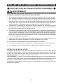
READ AND SAVE THESE INSTRUCTIONS
WARNING
TO REDUCE THE RISK OF FIRE, ELECTRIC SHOCK, OR INJURY TO PERSONS,
OBSERVE THE FOLLOWING:
1. Use this unit only in the manner intended by the manufacturer. If you have questions,
contact the manufacturer at the address or telephone number listed in the warranty.
2. Before servicing or cleaning unit, switch power off at service panel and lock service
panel to prevent power from being switched on accidentally. When the service discon-
necting means cannot be locked, securely fasten a prominent warning device, such
as a tag, to the service panel.
3. Installation work and electrical wiring must be done by a qualified person(s) in ac-
cordance with all applicable codes and standards, including fire-rated construction
codes and standards.
4. Sufficient air is needed for proper combustion and exhausting of gases through the
flue (chimney) of fuel burning equipment to prevent backdrafting. Follow the heating
equipment manufacturer’s guidelines and safety standards such as those published
by the National Fire Protection Association (NFPA), and the American Society for
Heating, Refrigeration and Air Conditioning Engineers (ASHRAE), and the local code
authorities.
5. When cutting or drilling into wall or ceiling, do not damage electrical wiring and other
hidden utilities.
6. Ducted fans must always be vented to the outdoors.
7. Do not use this unit with any separate solid-state speed control device.
8. To reduce the risk of fire, use only metal ductwork.
GROUNDING INSTRUCTIONS
This appliance must be grounded. In the event of an electrical short circuit, grounding
reduces the risk of electrical shock by providing an escape wire for the electric current.
This appliance is equipped with a cord having a grounding wire with a grounding plug.
The plug must be plugged into an outlet that is properly installed and grounded.
WARNING - Improper grounding can result in a risk of electric shock.
Consult a qualified electrician if the grounding instructions are not completely understood,
or if doubt exists as to whether the appliance is properly grounded.
Do not use an extension cord. If the power supply cord is too short, have a qualified
electrician install an outlet near the appliance.
!
INTENDED FOR DOMESTIC COOKING ONLY
!

- 3 -
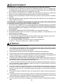
!
CAUTION
1. For indoor use only.
2. To reduce risk of fire and to properly exhaust air, be sure to duct air outside. Do not
vent exhaust air into spaces within walls or ceilings or into attics, crawl spaces, or
garages.
3. Take care when using cleaning agents or detergents.
4. Avoid using food products that produce flames under the Range Hood.
5. For general ventilating use only. Do not use to exhaust hazardous or explosive
materials and vapors.
6. To avoid motor bearing damage and noisy and/or unbalanced impellers, keep drywall
spray, construction dust, etc. off power unit.
7. Your hood motor has a thermal overload which will automatically shut off the motor
if it becomes overheated. The motor will restart when it cools down. If the motor
continues to shut off and restart, have the hood serviced.
8. For best capture of cooking impurities, the bottom of the hood should be a minimum
of 18-1/2” and a maximum of 30-1/2” above the cooking surface. See “Install Mount-
ing Bracket” section for mounting restrictions.
9. Two installers are recommended because of the large size and weight of this hood.
10. This product is equipped with a thermostat which may start blower automatically. To
reduce the risk of injury and to prevent power from being switched on accidentally,
switch power off at service panel and lock or tag service panel.
11. Please read specification label on product for further information and requirements.
WARNING
TO REDUCE THE RISK OF A RANGE TOP GREASE FIRE:
A. Never leave surface units unattended at high settings. Boilovers cause smoking and
greasy spillovers that may ignite. Heat oils slowly on low or medium settings.
B. Always turn hood ON when cooking at high heat or when flambéing food (i.e. Crepes
Suzette, Cherries Jubilee, Peppercorn Beef Flambé).
C. Clean ventilating fans frequently. Grease should not be allowed to accumulate on fan
or filter.
D. Use proper pan size. Always use cookware appropriate for the size of the surface
element.
TO REDUCE THE RISK OF INJURY TO PERSONS IN THE EVENT OF A RANGE TOP
GREASE FIRE, OBSERVE THE FOLLOWING:*
1. SMOTHER FLAMES with a close-fitting lid, cookie sheet, or metal tray, then turn off
the burner. BE CAREFUL TO PREVENT BURNS. If the flames do not go out imme-
diately, EVACUATE AND CALL THE FIRE DEPARTMENT.
2. NEVER PICK UP A FLAMING PAN - You may be burned.
3. DO NOT USE WATER, including wet dishcloths or towels - violent steam explosion
will result.
4. Use an extinguisher ONLY if:
A. You know you have a Class ABC extinguisher and you already know how to oper-
ate it.
B. The fire is small and contained in the area where it started.
C. The fire department is being called.
D. You can fight the fire with your back to an exit.
* Based on “Kitchen Fire Safety Tips” published by NFPA.

- 4 -
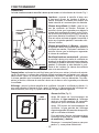
OPERATION
Controls
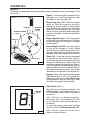
The hood is operated using the joystick control located on the front edge of the
hood. Fig. 1.
Filter Alarm (Fig. 2.)
After 30 hours of blower operation, the
Center Line of the Display will stay on
for 30 seconds each time the blower is
turned off.
After 120 hours of blower operation,
the center line of the display will flash
for 30 seconds each time the blower is
turned off.
To reset the alarm, press and hold the
joystick to the left: Blower Speed (-) Off.
Note: The hour count will not be lost if
there is a power failure.
FIG. 1
Lights - Push the joystick upward to turn
the lights on to low. Push again for high
and again to turn the lights off.
Blower Speed (-) Off - With the blower
motor on. Push the joystick to the left to
reduce the blower speed to the desired
level. Pushing the joystick past the lowest
speed will turn the blower off. If the filter
alarm is active, pressing and holding the
joystick to the left for 2 seconds resets the
filter alarm.
Blower Speed (+) On - Push the joystick
to the right to turn the blower on. Continue
to push the joystick to the right to increase
blower speed.
Blower/Lights, On/Off - Press the joystick
to turn on the blower to its last stored
speed. Press and hold the joystick in for 2
seconds and it will turn off the blower and
the lights (the blower speed will be stored).
Delay Off - Push the joystick downward
to activate the 10 minute timer function.
The blower speed on the display will start
blinking to indicate this function. After 10
minutes of operation, the motor will turn off.
If you change the speed while the timer is
running, the function is not deactivated. To
deactivate the function, press the joystick
downward or to the left to turn blower off.
Display - Shows the current blower speed.
When the blower is off it will indicate the
filter alarm: after 30 hours the Center Line
of the display will stay on. (See Fig. 2). After
120 hours the center line will flash.
DISPLAY
LIGHTS
BLOWER SPEED
(-) OFF
BLOWER
SPEED
(+) ON
FIG. 2
CENTER
LINE
DELAY OFF

- 5 -
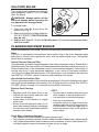
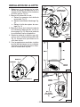
HALOGEN BULBS
This range hood requires two halogen
bulbs(included) (Type T3, 12 Volt, 20 Watt
Max, G4 Base).
WARNING: Always switch off the
electrical supply before carrying out
any operation on the appliance.
To change bulbs:
1. Open the cover by prying from the
proper slots. Fig. 3.
2. Remove the bulbs by pulling sideways.
(DO NOT ROTATE). CAUTION: Bulbs
may be hot.
3. Replace with Type T3, 12 Volt, 20 Watt Max bulbs. Do not touch replacement bulbs
with bare hands!
FIG. 3
CLEANING AND MAINTENANCE
Proper maintenance of the Range Hood will assure proper performance of the unit.
Motor
The motor is permanently lubricated and never needs oiling. If the motor bearings make
excessive or unusual noise, replace the motor with the exact service motor. The impeller
should also be replaced.
Grease Filter and Charcoal Filter
The grease filter should be cleaned frequently. Use a warm detergent solution. Grease filter is
dishwasher safe. The charcoal filter should be replaced when the charcoal filter alarm turns on.
Clean all-metal filters in the dishwasher using a non-phosphate detergent. Discoloration of
the filter may occur if using phosphate detergents, or as a result of local water conditions
- but this will not affect filter performance. This discoloration is not covered by the warranty.
See “INSTALL FILTERS” section for removal and installation instructions.
Non-ducted Recirculation Filter
The non-ducted recirculation filter should be changed every 6 months. Replace more often if
your cooking style generates extra grease, such as frying and wok cooking. See “INSTALL
FILTERS” section, on page 15, for removal and installation instructions.
Stainless Steel Cleaning
DO:
• Regularly wash with clean cloth or rag
soaked with warm water and mild soap
or liquid dish detergent.
• Always clean in the direction of original
polish lines.
• Always rinse well with clear water (2 or 3
times) after cleaning. Wipe dry completely.
• You may also use a specialized household
stainless steel cleaner.
DON’T:
•
Use any steel or stainless steel wool or any
other scrapers to remove stubborn dirt.
• Use any harsh or abrasive cleansers.
• Allow dirt to accumulate.
• Let plaster dust or any other construction
residues reach the hood. During construc-
tion/renovation, cover the range hood to
make sure no dust sticks to the stainless
steel surface.
Avoid: When choosing a detergent
• Any cleaners that contain bleach will attack stainless steel
• Any products containing: chloride, fluoride, iodide, bromide will deteriorate surfaces rapidly.
• Any combustible products used for cleaning such as acetone, alcohol, ether, benzol, etc.,
are highly explosive and should never be used close to a range.

- 6 -
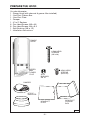
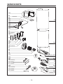
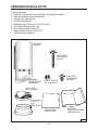
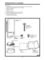
PREPARE THE HOOD
Unpack hood and check contents.
You should receive:
1 - Range Hood (with charcoal & grease filter installed)
1 - Non-Duct Plenum Box
1 - Non-Duct Plate
1 - Damper
1 - 6” to 5” Reducer
6 - Pan Head Screws, M5 x 38
8 - Pan Head Screws, M4 x 9.5
1 - Split Bushing (3/8 in. ID)
1 - Installation Instructions
DAMPER
8 PAN HEAD
SCREWS
(M4 x 9.5)
UPPER
AND
LOWER
FLUE
FIG. 4
6 PAN HEAD
SCREWS
(M5 x 38)
RANGE
HOOD
SPLIT
BUSHING,
3/8” ID
6” TO 5”
REDUCER
NON-DUCT
PLENUM
BOX
NON-DUCT
PLATE

- 7 -
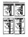
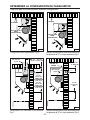
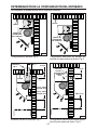
This hood can be ducted in these different configurations:
Non-ducted configuration. Fig. 5.
DETERMINE DUCTING CONFIGURATION
Ducted either Vertical or Horizontal.
F i g . 7.
FIG. 5
FIG. 7
4-15/16”
CEILING
6” DUCT
4”
18-1/2” FOR
8’ CEILINGS
30-1/2” FOR
9’ CEILINGS
CEILING
NON-DUCT
PLENUM
Alternate non-ducted configuration for
9-ft. ceilings only. Fig. 6.
Alternate ducted configuration for 9-ft.
ceilings only. Fig. 8.
FIG. 6
FIG. 8
4-15/16”
6” DUCT
OUTLET
BOX
18-1/2” MIN.
CEILING
NON-DUCT
PLENUM

- 8 -
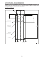
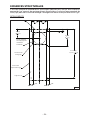
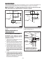
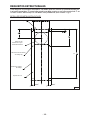
Special structure considerations must be made to ensure proper installation. The
mounting bracket needs to mounted to 2” nominal lumber in the six mounting holes.
Hollow wall anchors should not be used. Fig. 9.
ROUGH-IN DETAILS
1
1
4
"
8
3
4
"
2'-1
5
16
"
3
15
16
"
3
15
16
"
4
15
16
"
Top of Hood
6" Duct Location
For Horizontal Ducting
Mounting Hole
Locations (6)
2x4 Supports
Outline of
Mounting Plate
STRUCTURAL REQUIREMENTS
FIG. 9

- 9 -
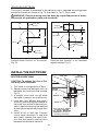
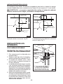
ROOF CAP
6-INCH
ROUND DUCT
HOOD
WALL
CAP
6”
DAMPER
18-1/2” TO 30-1/2” ABOVE
COOKING SURFACE
(see “INSTALL MOUNTING
BRACKETS” section for
mounting restrictions)
INSTALL THE DUCTWORK
DUCTED HOODS ONLY
CAUTION: To reduce the risk of fire,
use only metal ductwork.
1. This hood is configured for 6” duct.
2. Decide where the ductwork will run
between the hood and the outside.
Fig. 12.
3. A straight, short duct run will allow
the hood to perform most efficiently.
4. Long duct runs, elbows, and transi-
tions will reduce the performance of
the hood. Use as few of them as pos-
sible. Larger ducting may be required
for best performance with longer duct
runs.
5. Install a roof or wall cap. Connect
round metal ductwork to cap and
work back towards the hood loca-
tion. Use duct tape to seal the joints
between the ductwork sections.
FIG. 12
ROUGH-IN ELECTRICAL
This hood is corded. A receptacle in the ceiling or wall is required. Incoming power
should be located as shown in Fig. 10 (top view) or Fig. 11 (front view).
WARNING: Electrical wiring must be done by a qualified person in accor-
dance with all applicable codes and standards.
Ducted either Vertical or Horizontal.
Fig. 10.
8"
4"
Electrical
Box Location
6" Duct
Center Line
of Hood
Wall
FIG. 10
ROUND
ELBOW
Electrical box location is not mounted
against ceiling. Fig. 11.
4"
Electrical
Box Location
6" Duct
Center Line
of Hood
Top of Hood
1/2"
FIG. 11

- 10 -
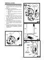
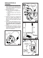
INSTALL HOOD
1. Flip hood cover down. Remove panel
by unscrewing thumb screw. Remove
grease filter and charcoal filter.
Fig. 13.
2. Separate the hood parts:
a. Remove the control box connec-
tor. Fig. 14.
b. Remove the lighting connector.
Fig. 14.
c. Remove the sensor box from the
mount. Fig. 14.
3. Separate the hood body from the
blower frame by unscrewing the
six (6) mounting screws (Fig. 15).
Remove the blower frame from the
shipping board.
4. Mount the hood frame to the wall us-
ing six (6) M5 x 38 Pan Head Screws.
Fig. 16. Make sure all screws are in
wood.
5. For ducted applications install the
damper onto the blower. Complete
the duct work. Plug power cord into
receptacle.
CONTROL
BOX
FIG. 14
MOUNTING
SCREWS (6)
FIG. 15
FIG. 16
HOOD
BODY
M8 x 38
PAN HEAD
SCREWS (6)
LIGHTING
CONNECTOR
SENSOR
BOX
HOOD
FRAME
FIG.13
KNOB
COVER
PANEL

- 11 -
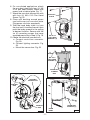
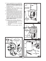
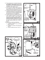
6. For non-ducted applications attach
the non-duct plate with four (4) M4
x 9.5 pan head screws. Make sure
power cord is behind plate. Fig. 17.
7. Attach the non-duct plenum box with
with four (4) M4 x 9.5 Pan Head
Screw. Fig. 18.
8. Place split bushing around power
cord and snap into non-duct plate.
Plug power cord into receptacle.
9. Take the hood body slide it in from
the front until it touches the wall, then
push the body upward to the ceiling
at desired location. Secure with the
six (6) mounting screws that were
removed previously in Step 3. Fig. 19.
10. Make the electrical connections:
a. Connect control box connector.
Fig. 20.
b. Connect lighting connector. Fig.
20.
c. Mount the sensor box. Fig. 20.
NON-DUCT
PLATE
FIG. 17
NON-DUCT
PLENUM
BOX
FIG. 18
M4 X 9.5
PAN HEAD
SCREWS (4)
M4 X 9.5
PAN HEAD
SCREWS (4)
CONTROL
BOX
FIG. 20
LIGHTING
CONNECTOR
SENSOR
BOX
FIG. 19
MOUNTING
SCREWS (6)
HOOD
BODY

- 12 -
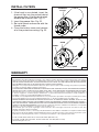
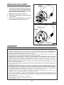
INSTALL FILTERS
1. If the hood is non-ducted, insert the
charcoal filter into the pocket behind
the grease filter. If the hood is ducted,
discard the charcoal filter. Fig. 21.
2. Insert the grease filter. Fig. 22.
3. Re-install panel and secure with the
thumb screw.
4. Close the bottom cover and remove
all of the protective coating. Fig. 22.
WARRANTY
ONE YEAR LIMITED WARRANTY FOR BEST PRODUCTS
Broan-NuTone LLC (Broan-NuTone) warrants to the original consumer purchaser of Best products that such products
will be free from defects in materials or workmanship for a period of one year from the date of original purchase. THERE
ARE NO OTHER WARRANTIES, EXPRESS OR IMPLIED, INCLUDING, BUT NOT LIMITED TO, IMPLIED WARRAN-
TIES OR MERCHANT ABILITY OR FITNESS FOR A PARTICULAR PURPOSE.
During this one-year period, Broan-NuTone will, at its option, repair or replace, without charge, any product or part which
is found to be defective under normal use and service.
THIS WARRANTY DOES NOT EXTEND TO FLUORESCENT LAMP STARTERS, TUBES, HALOGEN AND INCANDES-
CENT BULBS, FUSE, FILTERS, DUCTS, ROOF CAPS, WALL CAPS AND OTHER ACCESSORIES FOR DUCTING.
This warranty does not cover (a) normal maintenance and service or (b) any products or parts which have been subject
to misuse, negligence, accident, improper maintenance or repair (other than by Broan-NuTone), faulty installation or
installation contrary to recommended installation instructions.
The duration of any implied warranty is limited to the one-year period as specified for the express warranty. Some states
do not allow limitation on how long an implied warranty lasts, so the above limitation may not apply to you.
BROAN-NUTONE’S OBLIGATION TO REPAIR OR REPLACE, AT BROAN-NUTONE’S OPTION, SHALL BE THE
PURCHASER’S SOLE AND EXCLUSIVE REMEDY UNDER THIS WARRANTY. BROAN-NUTONE SHALL NOT BE LI-
ABLE FOR INCIDENTAL, CONSEQUENTIAL OR SPECIAL DAMAGES ARISING OUT OF OR IN CONNECTION WITH
PRODUCT USE OR PERFORMANCE. Some states do not allow the exclusion or limitation of incidental or consequential
damages, so the above limitation or exclusion may not apply to you.
This warranty gives you specific legal rights, and you may also have other rights, which vary from state to state. This
warranty supersedes all prior warranties.
To qualify for warranty service, you must (a) notify Broan-NuTone at the address stated below or telephone number stated
below, (b) give the model number and part identification and (c) describe the nature of any defect in the product or part.
At the time of requesting warranty service, you must present evidence of the original purchase date.
In USA - Best®, 926 W. State Street, Hartford, WI 53027 (800-558-1711)
In Canada - Best®, 550 Lemire Blvd., Drummondville, QC J2C 7W9 (866-737-7770)
www.BestRangeHoods.com
FIG. 21
FIG. 22
CHARCOAL
FILTER
KNOB
COVER
PANEL

- 13 -
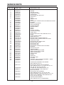
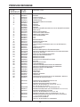
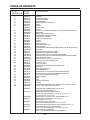
SERVICE PARTS
KEY NO. PART NO. DESCRIPTION
6 B02000191 SPRING
9 B08087165 GREASE FILTER
10 B03300502 CHARCOAL FILTER
14 B02300233 CONDENSER
16 BE3348772 ELECTRICAL BOX SUPPORT
26 B02300891 LAMP BULB
37 B02011355 KNOB
B02300804 THERMOSTAT
B02000690 KNOB
39 B03294033 ELECTRICAL PRINTED CIRCUIT BOARD BOX COVER
45 BW0000021 BLOWER
48 B02310260 MOTOR (CLOCKWISE)
49 B03295071 FAN (CLOCKWISE)
53 B03204177 RUBBER WASHER
60 B02300249 FEEDER CABLE
67 B02300970 WIRES
B02300971 WIRES
86 B08088378 OUTLET FLANGE
96 B03145724 PROTECTION PANEL
107 B03202287 CABLE STOP
118 B003102614 BOTTOM DUCT EXT. (INCLUDES KEY NO. 6)
122 B080810955 RISER
134 B02011262 LADLE HANGER HOOK
144 B03292287 WIRES STOP PIN
145 B032920170 FEEDER CABLE CONNECTION BOX
146 B032920180 FEEDER CABLE CONNECTION BOX COVER
147 BR2300132 JUNCTION CLAMP
151 B032920200 ELECTRICAL BOX WIRES STOP
154 B03202286 FEEDER CABLE STOP
165 B03294781 ELECTRICAL BOX
B03295008 ELECTRICAL BOX
166 B08080854 ELECTRICAL PRINTED CIRCUIT BOARD
195 BE3251389 BRACKET
202 B03292290 REFLECTOR STOP
208 B02300861 TRANSFORMER
230 B03294189 SWITCH BOARD BOX COVER
B03294191 SWITCH BOARD BOX COVER
234 B03294188 SWITCH BOARD BOX
312 BE3250198 INSIDE PANEL
332 BE3404871 COVER
415 B03202288 FAIRLEAD
474 B02300834 HALOGEN LAMP
477 B02011376 CLOSING
504 BW0000067 CONTROL CIRCUIT BOARD ASSEMBLY + KNOB
505 B08080321 CIRCUIT BOARD DISPLAY
* B06103988 CONDENSER ASSEMBLY WITH WIRES
(INCLUDES KEY NO. 14)
* B06145145 ELECTRICAL INSTALLATION ASSEMBLY
(INCLUDES KEY NO. 14, 37, 39, 67, 144, 145, 147,
165, 166, 208, 230, 234, 504, 505)
* B080810888 FITTING SET (INCLUDES KEY NO. 154)
* B06002157 BLOWER ASSEMBLY (INCLUDES KEY
NO. 45, 48, 49, 53)
* B06103991 ELECTRICAL BOX ASSEMBLY
(INCLUDES KEY NO. 39, 67, 144, 165, 166)
* B06103989 MAINS ASSEMBLY (INCLUDES KEY NO. 145, 147)
* B06103990 SWITCH BOX ASSEMBLY (INCLUDES KEY NO.
37, 67, 230, 234, 504, 505)
* B06103992 THERMOSTAT ASSEMBLY
(INCLUDES KEY NO. 37 THERMOSTAT)

- 14 -
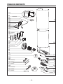
SERVICE PARTS
6
234
505
230 (03294191)
67 (02300971)
504
230 (03294189)
37 (02011355)
67 (02300970)
474
26
(02011376) 477
9
332
195
312
118
96
(02000690) 37
151
145
146
208
147
122
86
202
39
166
144
14
16
60
134
53
49
45
(02300804) 37
48
67 (02300972)
165 (03295008)
165 (03294781)
107
154
415
10

- 15 -
99044739B

- 16 -
ENGLISH .......................................... 2
FRANÇAIS ....................................... 16
ESPAÑOL......................................... 31
Aux ÉTATS-UNIS - BEST Hartford, Wisconsin
Au CANADA - BEST Drummondville, QC, Canada
ENREGISTREZ VOTRE PRODUIT EN LIGNE À L’ADRESSE: www.BestRangeHoods.com/register
Pour en savoir plus, visitez le site www.BestRangeHoods.com
Modèle WM33I40R

- 17 -
VEUILLEZ LIRE ET CONSERVER CES INSTRUCTIONS
AVERTISSEMENT
POUR RÉDUIRE LES RISQUES D’INCENDIE, D’ÉLECTROCUTION OU DE BLESSURES
PHYSIQUES, RESPECTEZ LES INSTRUCTIONS CI-DESSOUS:
1. Utilisez cet appareil uniquement de la manière prévue par le fabricant. Si vous avez des ques-
tions, contactez le fabricant à l’adresse ou au numéro de téléphone indiqués dans la garantie.
2. Avant d’effectuer l’entretien ou le nettoyage de l’appareil, mettez-le hors tension sur le pan-
neau de service et verrouillez ce dernier pour éviter que l’appareil soit mis sous tension par
inadvertance. S’il n’est pas possible de verrouiller le dispositif de déconnexion, apposez un
avertissement bien visible (par exemple une étiquette) sur le panneau de service.
3. L’installation et le raccordement électrique doivent être effectués par du personnel qualifié
conformément à toutes les réglementations et normes en vigueur, y compris celles concernant
les constructions cotées pour leur résistance au feu.
4. Afin d’éviter un refoulement lors de l’utilisation d’équipements à combustible, une quantité d’air
suffisante est nécessaire pour assurer une combustion et un échappement adéquats des gaz à
travers le conduit (la cheminée). Suivez les consignes du fabricant de l’équipement chauffant et
les normes de sécurité publiées, entre autres, par la National Fire Protection Association (NFPA)
et l’American Society for Heating, Refrigeration and Air Conditioning Engineers (ASHRAE),
ainsi que les réglementations locales.
5. Quand vous effectuez une découpe ou un forage dans un mur ou un plafond, veillez à ne pas
endommager des câblages électriques ou d’autres équipements non visibles.
6. Les soufflantes canalisées doivent toujours être dirigées vers l’extérieur.
7. N’utilisez pas cet appareil avec un dispositif de commande de vitesse transistorisée séparé.
8. Pour réduire les risques d’incendie, utilisez uniquement des canalisations en métal.
INSTRUCTIONS DE MISE À LA TERRE
Cet appareil doit être mis à la terre. En cas de court-circuit électrique, la mise à la terre réduit le
risque d’électrocution grâce à un fil permettant au courant électrique de s’échapper. Cet appareil
est doté d’un cordon ayant un fil de terre, ainsi que d’une fiche de mise à la terre. La fiche doit
être branchée dans une prise bien installée et mise à la terre.
AVERTISSEMENT - Une mise à la terre inappropriée peut donner lieu à un risque d’électrocution.
Consultez un électricien qualifié si vous ne comprenez pas parfaitement les instructions de mise
à la terre ou si vous n’êtes pas certain(e) que l’appareil est mis à la terre comme il se doit.
N’utilisez pas de rallonge. Si le cordon est trop court, demandez à un électricien d’installer une
prise près de l’appareil.
!
CONÇUE POUR LES CUISINES PRIVÉES UNIQUEMENT
!

- 18 -
!
ATTENTION
1. Uniquement pour l’utilisation intérieure.
2. Pour réduire le risque d’incendie et obtenir un échappement d’air adéquat, veillez à bien canaliser
l’air vers l’extérieur. Ne ventilez pas l’air d’échappement vers des espaces confinés, des plafonds,
des combles, des vides sanitaires ou des garages.
3. Soyez prudent(e) quand vous utilisez des agents de nettoyage ou des détergents.
4. Évitez d’utiliser sous la hotte de cuisine des denrées alimentaires produisant des flammes.
5. À utiliser uniquement pour la ventilation générale. N’utilisez pas la hotte pour l’échappement de
matériaux ou de vapeurs comportant un danger ou un risque d’explosion.
6. Pour éviter que le roulement moteur s’endommage et que des hélices deviennent bruyantes ou
déséquilibrées, faites en sorte que le bloc d’alimentation n’entre pas en contact avec un atomiseur
pour cloisons sèches, de la poussière de construction, etc.
7. Le moteur de la hotte est doté d’un rupteur thermique qui éteint automatiquement le moteur en
cas de surchauffe. Le moteur redémarrera après avoir refroidi. Si le moteur s’éteint et se rallume
constamment, faites réparer la hotte.
8. Pour mieux capturer les impuretés de cuisson, la partie inférieure de la hotte doit se trouver au
minimum à 47cm (181/2po) et au maximum à 75cm (301/2po) au-dessus de la surface de
cuisson. Consultez la section «Installation du support de montage» pour connaître les restrictions
de montage.
9. Étant donné la taille et le poids de la hotte, il est conseillé d’avoir recours à deux personnes pour
la monter.
10. Ce produit est doté d’un thermostat qui peut activer la soufflante automatiquement. Pour éviter les
risques de blessure et l’allumage accidentel de la hotte, mettez-la hors tension sur le panneau de
service et verrouillez ce dernier ou fixez-y une étiquette d’avertissement.
11. Pour en savoir plus et connaître les exigences sur le produit, veuillez lire l’étiquette des spécifica-
tions.
AVERTISSEMENT
POUR RÉDUIRE LE RISQUE D’UN FEU DE FRITURE SUR LA TABLE DE CUISSON
A. Ne laissez jamais les appareils de surface sans surveillance quand ils sont sur un réglage élevé.
Les débordements peuvent provoquer de la fumée et des déversements gras risquant de prendre
feu. Chauffez les huiles lentement sur un réglage bas ou moyen.
B. Allumez toujours la hotte quand vous cuisinez à une chaleur élevée ou quand vous flambez des
aliments (p. ex. des crêpes Suzette, des cerises jubilé ou du bœuf au poivre flambé).
C. Nettoyez souvent les ventilateurs d’aération. Évitez que la graisse ne s’accumule sur le ventilateur
ou le filtre.
D. Utilisez des poêles de la taille appropriée. Utilisez toujours des ustensiles de cuisine adaptés à la
taille de l’élément de surface.
POUR RÉDUIRE LE RISQUE DE BLESSURES PHYSIQUES EN CAS DE FEU DE FRITURE SUR
LA TABLE DE CUISSON, VEUILLEZ PROCÉDER COMME SUIT:*
1. ÉTOUFFEZ LES FLAMMES avec un couvercle hermétique, une plaque à biscuits ou un plateau
en métal, puis éteignez le brûleur. SOYEZ PRUDENT(E) AFIN D’ÉVITER LES BRÛLURES. Si les
flammes ne s’éteignent pas immédiatement, ÉVACUEZ LES LIEUX ET APPELEZ LE SERVICE
DES POMPIERS.
2. NE SAISISSEZ JAMAIS UNE POÊLE ENFLAMMÉE, vous risquez de vous brûler.
3. N’UTILISEZ JAMAIS D’EAU ni de torchons ou serviettes mouillé(e)s: cela donnerait lieu à une
violente explosion de vapeur.
4. Utilisez un extincteur UNIQUEMENT si:
A. Vous savez qu’il s’agit d’un extincteur de Classe ABC et savez déjà comment vous en servir.
B. L’incendie est de petite taille et confiné à l’endroit où il a commencé.
C. Le service des pompiers a été averti.
D. Vous pouvez éteindre l’incendie en ayant une sortie derrière vous.
* Basé sur «Kitchen Fire Safety Tips», publié par la NFPA.

- 19 -
FONCTIONNEMENT
Commandes
La hotte fonctionne avec le contrôle à levier qui se trouve sur le bord avant de la hotte. Fig. 1.
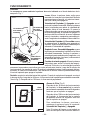
Alarme du filtre (Fig. 2.)
Après 30 heures de fonctionnement de
soufflante, la Ligne centrale de l’affichage
reste en marche pendant 30secondes
chaque fois que la soufflante est éteinte.
Après 120 heures de fonctionnement de
soufflante, la ligne centrale de l’affichage
clignotera pendant 30secondes chaque fois
que la soufflante est éteinte.
Pour réinitialiser l’alarme, enfoncez et tenez
le contrôle à levier vers la gauche : Vitesse
de soufflante (-) Arrêtée.
Remarque: Le compte d’heure ne sera pas
perdu s’i y a une panne d’électricité.
FIG. 1
Lumières - poussez le contrôle à levier vers
le haut pour allumer les lumières à faible in-
tensité. Enfoncez à nouveau pour obtenir une
haute intensité et à nouveau pour les éteindre.
Vitesse de soufflante (-) Arrêt - avec le mo-
teur de soufflante en marche. Enfoncez le
contrôle à levier vers la gauche pour réduire la
vitesse de la soufflante au niveau voulu. Enfon-
cer le contrôle à levier plus loin que la vitesse la
plus basse éteindra la soufflante. Si l’alarme de
filtre est active, enfoncer et garder le contrôle à
levier vers la gauche pendant 2 secondes réini-
tialisera l’alarme.
Vitesse de soufflante (+) Marche - enfoncez
le contrôle à levier vers la droite pour mettre la
soufflante en marche. Continuez à enfoncer le
contrôle à levier vers la droite pour augmenter
la vitesse de soufflante.
Soufflante/lumières, marche/arrêt - enfoncez
le contrôle à levier pour mettre la soufflante en
marche à la dernière vitesse mise en mémoire.
Enfoncez et gardez le contrôle à levier enfoncé
pendant 2 secondes et cela éteindra la souf-
flante et les lumières (la vitesse de soufflante
sera mise en mémoire).
Temporisation - enfoncez le contrôle à levier vers le bas pour activer la fonction de minute-
rie de 10 minutes. La vitesse de soufflante affichée commencera à clignoter pour indiquer
cette fonction. Après 10 minutes de fonctionnement, le moteur s’éteindra. Si vous changez
la vitesse pendant que la minuterie fonctionne, la fonction n’est pas désactivée. Pour dés-
activer la fonction, enfoncez le contrôle à levier vers le bas ou vers la gauche pour éteindre
la soufflante.
Affichage - montre la vitesse actuelle de la soufflante. Lorsque la soufflante est éteinte, il y
aura une indication d’alarme du filtre : après 30 heures, la ligne centrale de l’affichage res-
tera en marche. (Voir la fig. 2). Après 120 heures, la ligne centrale clignotera.
AFFICHAGE
LUMIÈRES
VITESSE DE
SOUFFLANTE
(-) ARRÊT
SOUF-
FLANTE
VITESSE
(+) MARCHE
FIG. 2
LIGNE
CENTRALE
TEMPORISATION

- 20 -
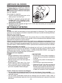
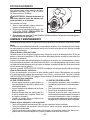
AMPOULES HALOGÈNES
Cette hotte de cuisine nécessite deux ampoules
halogènes (Type T3, 12V, 20W max., Base G4).
AVERTISSEMENT: Désactivez tou jours
l’alimentation avant d’effectuer toute opéra-
tion sur l’appareil.
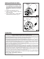
Pour changer les ampoules:
1. Ouvrez le couvercle en faisant levier sur les
fentes prévues à cet effet. Fig. 3.
2. Retirez les ampoules en les tirant vers
le côté. (NE LES TOURNEZ PAS).
ATTENTION: Il est possible que les am-
poules soient chaudes.
3. Remplacez par des ampoules de Type T3, 12V, 20W max. Ne touchez pas les ampoules de
rechange à mains nues !
FIG. 3
NETTOYAGE ET ENTRETIEN
Pour assurer les performances de l’appareil, entretenez-le de manière appropriée.
Moteur
Le moteur est lubrifié en permanence et aucun graissage n’est nécessaire. Si les roulements du
moteur font un bruit excessif ou inhabituel, remplacez le moteur par une pièce de rechange identique.
Remplacez aussi les hélices.
Filtres à charbon et filtre à graisse
Le filtre à graisse doit être nettoyé souvent. Vous pouvez utiliser une solution détergente chaude.
Le filtre à graisse peut être mis dans le lave-vaisselle. Le filtre à charbon doit être remplacé lorsque
l’alarme du filtre à charbon se met en marche.
Nettoyez tous les filtres en métal dans le lave-vaisselle avec un détergent sans phosphate. Si vous
utilisez un détergent phosphaté ou selon le type d’eau, il est possible que le filtre se décolore, mais
cela n’affectera aucunement ses performances. Cette décoloration n’est pas couverte par la garantie.
Consultez la section «INSTALLATION DES FILTRES» pour connaître les instructions de retrait et d’installation.
Filtre de recirculation non canalisé
Le filtre de recirculation non canalisé doit être changé tous les 6mois. Si votre style de cuisine
engendre beaucoup de graisse, par exemple si vous faites souvent de la friture ou utilisez un wok,
remplacez-le plus souvent. Consultez la section «INSTALLATION DES FILTRES» de la page 15
pour connaître les instructions de retrait et d’installation.
Nettoyage de l’acier inoxydable
À FAIRE:
• Nettoyez régulièrement l’acier inoxydable avec
un chiffon ou un torchon enduit d’eau chaude
et de savon doux ou de liquide vaisselle.
• Nettoyez toujours dans le sens des lignes de
polissage d’origine.
• Rincez toujours à l’eau claire (2 ou 3fois)
après le nettoyage. Essuyez complètement.
• Vous pouvez aussi utiliser un nettoyant spécial
pour acier inoxydable d’électroménagers.
À NE PAS FAIRE:
• N’utilisez pas de laine d’acier inoxydable ni
d’autres racloirs pour éliminer la saleté difficile
à éliminer.
• N’utilisez pas de produits de nettoyage durs
ou abrasifs.
• Ne laissez pas la poussière s’accumuler.
• Maintenez la hotte à l’abri de la poussière de
plâtre ou d’autres résidus de construction.
Pendant la construction/les rénovations, cou-
vrez la hotte afin d’éviter qu’aucune poussière
n’adhère aux surfaces en acier inoxydable.
À éviter: Quand vous choisissez un détergent
• Tous les produits de nettoyage contenant de l’eau de Javel attaquent l’acier inoxydable.
• Tous les produits contenant du chlore, du fluor, de l’iode ou du bromure provoquent une détérioration
rapide des surfaces.
• Tous les produits combustibles utilisés pour le nettoyage, tels que l’acétone, l’alcool, l’éther, le
benzène sont extrêmement explosifs et ne doivent jamais être employés à proximité d’une table
de cuisson.
La page charge ...
La page charge ...
La page charge ...
La page charge ...
La page charge ...
La page charge ...
La page charge ...
La page charge ...
La page charge ...
La page charge ...
La page charge ...
La page charge ...
La page charge ...
La page charge ...
La page charge ...
La page charge ...
La page charge ...
La page charge ...
La page charge ...
La page charge ...
La page charge ...
La page charge ...
La page charge ...
La page charge ...
La page charge ...
-
 1
1
-
 2
2
-
 3
3
-
 4
4
-
 5
5
-
 6
6
-
 7
7
-
 8
8
-
 9
9
-
 10
10
-
 11
11
-
 12
12
-
 13
13
-
 14
14
-
 15
15
-
 16
16
-
 17
17
-
 18
18
-
 19
19
-
 20
20
-
 21
21
-
 22
22
-
 23
23
-
 24
24
-
 25
25
-
 26
26
-
 27
27
-
 28
28
-
 29
29
-
 30
30
-
 31
31
-
 32
32
-
 33
33
-
 34
34
-
 35
35
-
 36
36
-
 37
37
-
 38
38
-
 39
39
-
 40
40
-
 41
41
-
 42
42
-
 43
43
-
 44
44
-
 45
45


Best WM33I40R Guide d'installation
- Catégorie
- Hottes
- Taper
- Guide d'installation
dans d''autres langues
- español: Best WM33I40R Guía de instalación