Modern Forms PD-24826 Veloce Mode d'emploi
- Catégorie
- Mur
- Taper
- Mode d'emploi

1
modernforms.com
Phone (800) 526.2588
Fax (800) 526.2585
Headquarters/Eastern Distribution Center
44 Harbor Park Drive
Port Washington, NY 11050
Central Distribution Center
1600 Distribution Ct
Lithia Springs, GA 30122
Western Distribution Center
1750 Archibald Avenue
Ontario, CA 91760
INSTALLATION INSTRUCTION
248-LED Pendant
PD-2482 /PD-2483
HARDWARE
WARNING
- Read all instructions before installing.
- Go to the main fuse box, or circuit breaker. Place the main power switch in the “OFF” position and unscrew the fuse(s) or switch ”OFF”
- Place the wall switch in the “OFF” position.
CAUTION
- All parts must be used as indicated in these instructions. Do not substitute any parts, leave parts out, or use any parts that are
AVERTISSEMENT
IMPORTANT : Coupez l’électricité avant TOUTE manipulation.
- Lisez toutes les instructions avant d’installer.
règlements locaux.
- Accédez au panneau central de disjoncteurs ou de fusibles de votre demeure et placez l’interrupteur principal en position d’arrêt
(« OFF »).
- Placez l’interrupteur mural en position d’arrêt (« OFF »).
MISE EN GARDE
- Toutes les pièces doivent être utilisées tel qu’il est indiqué dans ces instructions. Ne remplacez pas les pièces, n’en laissez pas de côté
et ne les utilisez pas si elles sont usées ou brisées. Le non-respect de ces instructions peut annuler l’homologation ETL/CETL du
luminaire. MISE EN GARDE Ors de la manipulation de l’appareil, ne pas appliquer de pression à la LED, tenir l’appareil par la seule base.
ADVERTENCIA
IMPORTANTE: NUNCA intente hacer trabajos sin desconectar el suministro eléctrico.
- Lea y comprenda todas las instrucciones e ilustraciones por completo antes de proceder con el ensamblaje e insta lación de esta
lámpara.
- Diríjase a la caja de fusibles o a la caja del interruptor de circuito principal en su hogar. Coloque el interruptor de ali mentación
principal en la posición “OFF” (APAGADO).
- Coloque el interruptor de la pared en la posición “OFF” (APAGADO).
PRECAUCIÓN
- Todas las piezas deben usarse como lo indican estas instrucciones. No reemplace las piezas, noomita piezas durante la instalación ni
ETL/CETL esta lámpara. PRECAUCIÓN Al manipular el aparato, no aplique presión a los LED, mantenga el aparato en la base sólo.
Wire Connector
Qty: 3pcs+1Extra
7EAC112201 P3
Junction Box Screw
Qty: 2pcs+1 Extra
7MPF0415C2
#8-32x5/8 SS
Mounting Screw
Qty:1 Extra
7MPF0408C1
5/32-32x5/8
Nickel Plating
Plastic Anchor
Qty: 3pcs+1 Extra
7TDD082401
Wood Screw
Qty: 3pcs+1 Extra
7MPF2204J2
A B C D E
G0
Wire
Connector
Qty: 3pcs+1Extra
7EAC112201
P3
Mounting
Screw
Qty:1 extra
7MPF0408C1 (TT)
7MPF0408C1BK (BK)
5/32-32x5/8
Junction Box
Screw
Qty: 2pcs+1 extra
7MPF0415C2
#8-32x5/8 SS
A B C D E
Plastic Anchor
Qty: 3pcs+1 extra Qty: 3pcs+1 extra

2
modernforms.com
Phone (800) 526.2588
Fax (800) 526.2585
Headquarters/Eastern Distribution Center
44 Harbor Park Drive
Port Washington, NY 11050
Central Distribution Center
1600 Distribution Ct
Lithia Springs, GA 30122
Western Distribution Center
1750 Archibald Avenue
Ontario, CA 91760
INSTALLATION INSTRUCTION
248-LED Pendant
PD-2482 /PD-2483
PREPARATION
parts on a clear area. Be careful not to lose any small
parts necessary for installation.
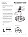
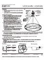
MOUNTING THE FIXTURES (Fig. 1)
4. Drill holes in the wall aligned with the key holes
located in the mounting back plate, insert the plastic
anchor (D).
5. Secure back plate to the junction box using junction
box screws (B), fasten it to the wall using wood screw
(E).The side of the mounting plate marked “GND”
must face out.
gripper on the canopy and pulling the wire as
desired.
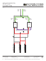
CONNECTING THE WIRES (Fig. 2)
7. Connect the driver input wires with junction box
wires as shown in Fig.2, making sure that all wire
connectors (A) are secured. If your outlet box has
a green or bare copper ground wire, connect the
using the green screw provided. After wires are
connected, tuck them carefully inside the junction
box.
with mounting screws (C).
Fixture Wires
Black or
Smooth
Fixture Wires
White or
Ribbed
Fixture Wires
Bare wire
(Ground)
House Wires
Black
(Hot)
House Wires
White
(Neutral)
House Wires
Green or Bare Copper
(Ground)
Fig. 2 Wiring
FIG. 1
BACK PLATE DIMENSIONS
G0
Junction Box
Wire Connector
Ground Wire
Plastic Anchor
Junction Box Screw
Wood Screw
Mounting Screw
Back Plate
Driver
3 1/2”LX2 3/8”WX1 1/4”H
Cable-gripper Push Up
87
8"
31
2"
11
2"
8 7/8”
1 1/2”
3 1/2”
A
D
B
E
C
8 7/8”
1 1/2”
3 1/2”
7MBB231101
Junction Box
Wire Connector
A
Ground Wire
Wood Screw
Plastic Anchor
D
E
Junction Box
Screw
B
Back Plate
Mounting
Screw
C
Cable-gripper Push up
Driver
3 1/2"LX2 3/8"WX1 1/4"H
Safety
C
ords
87
8"
31
2"
13
4"13
8"
Junction Box
Wire Connector
A
Ground Wire
Wood Screw
Plastic Anchor
D
E
Junction Box
Screw
B
Back Plate
Mounting
Screw
C
Cable-gripper Push up
Driver
3 1/2"LX2 3/8"WX1 1/4"H
Safety
C
ords
4. I Drill holes in the wall aligned with the key holes located
in the mounting back plate, insert the plastic anchor (D).
5. Secure back plate to the junction box using junction box
screws (B), fasten it to the wall using wood screw (E).The
side of the mounting plate marked “GND” must face out.
6. Adjust the xture wire length by pushing the cable gripper
on the canopy and pulling the wire as desired. Make sure
the wires are the same length.
a. Retract these wires close to a desirable length to within
the canopy before securing the xture in place. Using
the cable gripper to adjust more than 18” of wire length
is not desirable.
b. Warning: Shortening these cables without professional
helps or electronic background is not advisable. Any
modications to the xture will result in voiding the
warranty of the product.
3. Remove the mounting screw (C) from the xture.
MOUNTING THE FIXTURE (Fig. 1)
CONNECTING THE WIRES (Fig. 2)
1. Shut o the power at the circuit breaker and remove existing
xture, including the crossbar.
2. Carefully unpack your new xture and lay out all the parts on
a clear area. Be careful not to lose any small partsnecessary
for installation.
PREPARATION
7. Connect the driver input wires with junction box wires as
shown in Fig.2, making sure that all wire connectors (A)
are secured. If your outlet box has a green or bare copper
ground wire, connect the xture’s ground wire to it.
Otherwise, connect the xture’s ground wire directly to
the mounting plate using the green screw provided.
After wires are connected, tuck them carefully inside
the junction box.
8. Hook the safety cords to the back plate.
9. Place the xture over the back plate and secure it with
mounting screws (C) .
10. After installed , adjust the outer ring like the graphical( FIG.1)
position.
Junction Box
Wire Connector
A
Ground Wire
Wood Screw
Plastic Anchor
D
E
Junction Box
Screw
B
Back Plate
Mounting
Screw
C
Cable-gripper Push up
Driver
3 1/2"LX2 3/8"WX1 1/4"H
Safety
C
ords
Adjust the fixture wire
length by pushing the
cable gripper on the
canopy and pulling the
wire as desired.
4. I Drill holes in the wall aligned with the key holes located
in the mounting back plate, insert the plastic anchor (D).
5. Secure back plate to the junction box using junction box
screws (B), fasten it to the wall using wood screw (E).The
side of the mounting plate marked “GND” must face out.
6. Adjust the xture wire length by pushing the cable gripper
on the canopy and pulling the wire as desired. Make sure
the wires are the same length.
a. Retract these wires close to a desirable length to within
the canopy before securing the xture in place. Using
the cable gripper to adjust more than 18” of wire length
is not desirable.
b. Warning: Shortening these cables without professional
helps or electronic background is not advisable. Any
modications to the xture will result in voiding the
warranty of the product.
3. Remove the mounting screw (C) from the xture.
MOUNTING THE FIXTURE (Fig. 1)
CONNECTING THE WIRES (Fig. 2)
1. Shut o the power at the circuit breaker and remove existing
xture, including the crossbar.
2. Carefully unpack your new xture and lay out all the parts on
a clear area. Be careful not to lose any small partsnecessary
for installation.
PREPARATION
7. Connect the driver input wires with junction box wires as
shown in Fig.2, making sure that all wire connectors (A)
are secured. If your outlet box has a green or bare copper
ground wire, connect the xture’s ground wire to it.
Otherwise, connect the xture’s ground wire directly to
the mounting plate using the green screw provided.
After wires are connected, tuck them carefully inside
the junction box.
8. Hook the safety cords to the back plate.
9. Place the xture over the back plate and secure it with
mounting screws (C) .
10. After installed , adjust the outer ring like the graphical( FIG.1)
position.
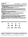
11. Please follow these if shortening the wire is needed. Take note or
take picture of how the wires are being connected and label each
wire clearly. Using the gure X as given below as reference( FIG.3).
Junction Box
Wire Connector
A
Ground Wire
Wood Screw
Plastic Anchor
D
E
Junction Box
Screw
B
Back Plate
Mounting
Screw
C
Cable-gripper Push up
Driver
3 1/2"LX2 3/8"WX1 1/4"H
Safety
C
ords
Adjust the fixture wire
length by pushing the
cable gripper on the
canopy and pulling the
wire as desired.

3
modernforms.com
Phone (800) 526.2588
Fax (800) 526.2585
Headquarters/Eastern Distribution Center
44 Harbor Park Drive
Port Washington, NY 11050
Central Distribution Center
1600 Distribution Ct
Lithia Springs, GA 30122
Western Distribution Center
1750 Archibald Avenue
Ontario, CA 91760
INSTALLATION INSTRUCTION
248-LED Pendant
PD-2482 /PD-2483
G0
FIG. 1
FIG. 3
Black -
Hot
White -
Neutral
Black
- Hot
White -
Neutral
- +
Black -
Hot
White -
Neutral
Internal Wire
External
Braided
Wire
Internal Wire
External
Braided
Wire
Driver
Dimmer
(
Purple
)
Dimmer
(
Ashy
)
Driver
- +
Input
Out
put
Out
put
Input
External
Braided
Wire
Internal Wire

1
Phone (800) 526.2588
Fax (800) 526.2585
44 Harbor Park Drive
Port Washington, NY 11050
1600 Distribution Ct
Lithia Springs, GA 30122
1750 Archibald Avenue
Ontario, CA 91760
INSTALLATION INSTRUCTIONS
PD-24848

2
Phone (800) 526.2588
Fax (800) 526.2585
44 Harbor Park Drive
Port Washington, NY 11050
1600 Distribution Ct
Lithia Springs, GA 30122
1750 Archibald Avenue
Ontario, CA 91760
INSTALLATION INSTRUCTIONS
PD-24848
Black or
Smooth
White or
Ribbed
Bare wire
(Ground)
Black
(Hot)
White
(Neutral)
Green or Bare Copper
(Ground)
Purple - Dim+
Pink or gray - Dim-
Black - Hot
White - Neutral
Red - Fixtrue+
Black - Fixtrue-
7 7/8"
1 3/8" 1 3/4"
A
C
D
C
B
.
wire(ground). pink or gray(dim-),black(hot),white(neutral) and bare copper ground
-
 1
1
-
 2
2
-
 3
3
-
 4
4
-
 5
5


Modern Forms PD-24826 Veloce Mode d'emploi
- Catégorie
- Mur
- Taper
- Mode d'emploi
dans d''autres langues
Documents connexes
-
Modern Forms PD-62864 Riddle Mode d'emploi
-
-
-
-
-
-
-
-
-