American Standard ASYSTAT625A Installer's Manual
- Taper
- Installer's Manual

® U.S. Registered Trademark
Copyright © 2003 • All Rights Reserved
INSTALLER’S GUIDE
69-1699
ASYSTAT625A
Humidity Control
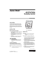
APPLICATION
The humidity control provides automatic low voltage
control of humidifiers in central heating and cooling
equipment for both humidification and dehumidification
applications. See Fig. 1. It has an spst, snap-acting,
dust-proof switch that opens when humidity rises above
the control setting. It is designed for wall or surface duct
mounting.
INSTALLATION
When Installing this Product...
1. Read these instructions carefully. Failure to follow
them could damage the product or cause a haz-
ardous condition.
2. Check the ratings given in the instructions and on
the product to make sure the product is suitable
for your application.
3. Installer must be a trained, experienced service
technician.
4. After installation is complete, check out product
operation as provided in these instructions.
CAUTION
Personal Injury Hazard.
Power supply can cause electrical shock.
Disconnect power supply before beginning
installation.
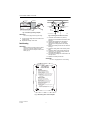
Location and Mounting
A mounting template is included for mounting the
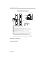
humidity control next to your thermostat. See Fig. 2.
However, the humidity control can be mounted in any
other convenient location in the living area or equipment
room.
NOTE: The humidity control electrical connections are
not shared with the thermostat.
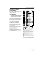
Fig. 1. Humidity control.
Wall Mounting
IMPORTANT
Mount the control in an area with average
room temperature and average relative
humidity.
Select a location for mounting the humidity control:
1. Hold the mounting template (included) next to
your thermostat. Select the mounting side for the
humidity control. The template is reversible for
mounting on either the left or right side of the
humidity control. See Fig. 2.
2. Mark the holes for the two mounting screws
(included). Then mark the hole for the low voltage
wiring on the template that corresponds with the
side selected in step 1.
3. Remove the template and drill the holes.
4. Run low voltage wiring to the location and pull
about 6 in. (152 mm) of wire through the hole.
5. Plug hole with nonflammable insulation to prevent
drafts from affecting the control operation.
6. Remove the humidity control case from the base.
See Fig. 1.
7. Position the base on the wall with the arrow up.
8. Use the two in. (25 mm) mounting screws to
secure the base to the wall.
M19844
CASE REMOVAL
SLOT
HOLE FOR WIRING
THE DUCT MOUNTING
INSTALLATIONS
Hum
id
ity Cont
rol
Pub. No.: 12-5034-01

ASYSTAT625A HUMIDITY CONTROL
69-1698 2
Pub.No.: 12-5034-01
Fig. 2. Positioning mounting template.
IMPORTANT
Use 18- to 22-gauge wire for proper wiring.
9. Connect the low voltage wires to the leads on the
humidity control.
10. Replace the humidity control case.
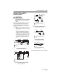
Duct Mounting
IMPORTANT
When mounting near an elbow area, locate the
control 6 in. (152 mm) upstream from the
elbow so the element is exposed to the normal
airflow (Fig. 3).
Fig. 3. Selecting duct location for control.
1. Locate the control at least 8 in. (203 mm)
upstream from the humidifier in the return air duct.
See Fig. 3.
2. Apply the duct template to the duct location.
3. Use the duct template, Fig. 4, to make the
opening and mounting holes for the humidity
control.
4. Remove the humidity control case from the base.
See Fig. 1.
5. Position the foam gasket on the humidity control
base.
6. Position the base on the duct with the arrow up.
7. Use the four 1 in. (25 mm) mounting screws to
secure the base to the duct.
8. Connect the low voltage wires to the leads on the
humidity control.
9. Replace the humidity control case.
IMPORTANT
Use 18- to 22-gauge wire for correct wiring.
Fig. 4. Positioning return air duct template.
M19830
THERMOSTAT
WALLPLATE
MOUNTING
TEMPLATE
MOUNTING
HOLES (2)
WIRING HOLES FOR MOUNTING ON RIGHT.
USE LEFT HOLES FOR MOUNTING ON LEFT.
ALTERNATE LOCATION
RETURN
AIR
RETURN
AIR
6 in. (152 mm)
MINIMUM
15 in. (381 mm)
MINIMUM
BEST
LOCATION
RETURN AIR DUCT
M13369
CAUTION
Equipment Damage Hazard.
Be careful when selecting control
location and cutting hole in ductwork.
Do not cut or drill into air conditioning
or electrical accessories.
Do not install control on supply (hot air) ductwork.
To use template:
1. Remove backing and apply template to duct.
2. Cut along template dotted line and drill the
mounting holes.
4X DRILL 7/64 IN. DIAMETER
PERCER 4 X 7/64 PO.
MISE EN GARDE
Risque d'endommager le matériel.
Faire attention au moment de choisir
l'emplacement du régulateur et de percer les
trous dans la gaine.
Ne pas couper ou percer les accessoires
électriques ou de climatisation.
Ne pas installer le régulateur sur la gaine
d'alimentation (air chaud).
Utilisation du gabarit:
1. Retirer l'endos du gabarit et placer le gabarit
sur la gaine.
2. Couper le long de la ligne pointillée du gabarit
et percer les trous de fixation.
DUCT TEMPLATE
GABARIT DE GAINE
M13373

ASYSTAT625A HUMIDITY CONTROL
3 69-1699
Pub.No.:12-5034-01
HEATING CYCLE HUMIDITY
CONTROL WIRING
CAUTION
Personal Injury Hazard.
Power supply can cause electrical shock and
injury.
Disconnect power supply before installation or
servicing.
All wiring must comply with applicable local codes, ordi-
nances and regulations. Make wiring connections
according to humidifier instructions, if available; other-
wise, see typical wiring diagrams in Fig. 5 through 9.
IMPORTANT
Select models of fan centers include humidifer
taps so the current sensing relay or sail switch
is not needed.
If not using a current sensing relay or sail
switch, the humidifier must be energized dur-
ing blower motor cycles for proper operation.
On multispeed blower applications, do not wire
the high voltage side of the transformer to the
same power source that services the furnace
blower. Premature transformer burnout can
occur.
Fig. 5. Typical wiring diagram for
system with fan interlock.
Fig. 6. Typical wiring diagram for system
with 2-speed fan motor.
Fig. 7. Typical wiring diagram of current
sensing relay with humidifier.
Fig. 8. Typical wiring diagram
of sail switch with humidifier.
Fig. 9. Typical wiring diagram for steam humidifiers.
1
1
2
PROVIDE DISCONNECT MEANS AND OVERLOAD PROTECTION
AS REQUIRED.
24 VAC WIRING.
2
HUMIDIFIER
TRANSFORMER
FURNACE
FAN
MOTOR
HUMIDISTAT
FAN CONTROL
L1
(HOT)
L2
M19831
POWER
SUPPLY
1
1
HL
C
2
POWER SUPPLY. PROVIDE DISCONNECT MEANS AND OVERLOAD
PROTECTION AS REQUIRED.
24 VAC WIRING.
2
HUMIDIFIER
TRANSFORMER
2-SPEED
FAN
MOTOR
DPST
SWITCHING
RELAY
HUMIDISTATFAN CONTROL
L1
(HOT)
L2
M19832
POWER
SUPPLY
M19833
L1
(HOT)
L2
1
2
1
2
POWER SUPPLY. PROVIDE DISCONNECT MEANS
AND OVERLOAD PROTECTION AS REQUIRED.
24V WIRING.
HUMIDIFIER
TRANSFORMER
WATER
SOLENOID
LEAD WIRE
CURRENT
SENSING
RELAY
C
LO
HI
HUMIDISTAT
M19834
L1
(HOT)
L2
1
2
1
2
POWER SUPPLY. PROVIDE DISCONNECT MEANS
AND OVERLOAD PROTECTION AS REQUIRED.
24V WIRING.
HUMIDIFIER
TRANSFORMER
HUMIDISTAT
SAIL
SWITCH
M19835
1
1
1
FOLLOW THE INSTALLATION INSTRUCTIONS
INCLUDED WITH THE STEAM HUMIDIFIER
TO WIRE THE SYSTEM FAN.
NOTE:
HUMIDIFIER
HUMIDISTAT
TO
SYSTEM
FAN
HUMIDISTAT
TERMINALS
FAN WIRING
TERMINALS
24V WIRING.

ASYSTAT625A HUMIDITY CONTROL
69-1698 4
Pub.No.: 12-5034-01
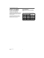
HEATING CYCLE HUMIDITY
CONTROL ADJUSTMENTS
Humidity Control Adjustment
To maintain optimum humidity control without causing
condensation on cold surfaces such as windows, the
homeowner must adjust the setpoint as the outdoor
temperature changes.
To reduce relative humidity, reduce the setpoint
approximately 3% RH humidity every 24 hours. To
increase relative humidity, increase the setpoint
approximately 3% RH every 24 hours.
Setpoint Adjustment
Set the humidity setpoint according to the prevailing
outdoor temperature. See Table 1 for recommended
settings.
Table 1. Recommended Humidity Control Setting.
Outdoor Temperature Recommended
Humidity Control
Setting°F °C
-20 -29 15
-10 -23 20
0 -18 25
+10 -12 30
+20 -7 35
>+20 >-7 40

ASYSTAT625A HUMIDITY CONTROL
5 69-1699
Pub.No.:12-5034-01
COOLING CYCLE HUMIDITY
CONTROL WIRING
See Fig. 10 and 11 for air handler and furnace wiring for
cooling cycle humidity control.
CAUTION
Personal Injury Hazard.
Power supply can cause electrical shock and
injury.
Disconnect power supply before installation or
servicing.
All wiring must comply with applicable local codes, ordi-
nances and regulations. Make wiring connections
according to humidifier instructions, if available; other-
wise, see typical wiring diagrams in Fig. 9 and 10.
COOLING CYCLE HUMIDITY
CONTROL ADJUSTMENTS
It is desirable to maintain the humidity in the living
space at the humidification comfort range of 25 to 50
percent relative humidity.
To reduce the relative humidity, position the arrow on
the humidity control to the humidity control setting:
40 setting controls to 40+/-10% RH.
50 setting controls to 50+/-10% RH.
When activated, the humidity control lowers the
furnace/air handler blower speed, reducing air velocity
over the furnace/air handler coil and removing a geater
amount of moisture from the air.
Fig. 10. Wiring for variable-speed air handler.
5
6
SUPPL. HTR.
CONTROL BOX
8
3
7
2
1 LOW VOLTAGE WIRING TO BE NO. 18 A.W.G. MINIMUM CONDUCTOR.
2 WHEN HEATERS ARE USED, DISCARD POWER LEADS WITH
POLARIZED PLUG PM-A AND CONNECT 1-PF TO MATING PLUG IN
THE HEATER CONTROL BOX AS SHOWN.
3 TERMINALS W2 WILL HAVE INTERNAL CONNECTIONS ONLY IF 2ND
CONTACTOR IS USED BY THE HEATER FOR CONTROLLING POWER
TO ELECTRIC HEATING ELEMENTS. IF 2ND (BH) CONTACTOR IS NOT
USED, THEN FIELD CONNECTIONS TO W2 CAN BE OMITTED AS
APPROPRIATE.
4 IF ODT IS NOT USED, THEN CONNECT APPROPRIATE JUMPER
FROM W1 TO W2 TO W3 ON LVTB.
5 IF HUMIDISTAT IS NOT USED, CONNECT JUMPER FROM "R" TO "BK"
FOR FULL TONNAGE AIRFLOW IN COOLING.
6 CONNECT IN THIS MANNER IF O.D. UNIT HAS "F" CONNECTION.
7 CONNECT W3 TO W2 ONLY IF USING HEATER WITH 3 HEATER STAGES.
8 SEE HEATER WIRING DIAGRAM FOR HEATING ANTICIPATOR SETTING.
24 V
FACTORY WIRING
INTER-COMPONENT WIRING
LINE V
TO POWER SUPPLY PER
LOCAL CODES AND AS
DEFINED IN FIELD WIRING TABLE
4
THERMOSTAT
VARIABLE SPEED
AIR HANDLER
HEAT PUMP
O.D. SECTION
(SINGLE SPEED)
HUMIDISTAT
T
X2
W
G
Y
Y/Y2
O
R
U
BB
F
W2
BK
W3
W1
G
O
T
R
T
YI/YLo
R
O
Y
ODT
BR/X2
OR BK
B
F
24 V
LINE V
FIELD WIRING
M19852

ASYSTAT625A HUMIDITY CONTROL
69-1698 6
Pub.No.: 12-5034-01
Fig. 11. Wiring for variable-speed, 2-stage furnace (2H/1C) using 1H/1C thermostat.
OPERATION AND CHECKOUT
Place the system in operation and observe through at
least one complete cycle to make certain that all
components are functioning correctly.
FIELD WIRING DIAGRAM FOR VARIABLE SPEED 2 STAGE FURNACE
2 STAGE HEATING, 1 STAGE COOLING
USING A 1 STAGE HEATING, 1 STAGE COOLING THERMOSTAT
(OUTDOOR SECTION WITHOUT TRANSFORMER)
7
6
9
5
5
THERMOSTAT
VARIABLE SPEED
2-STAGE FURNACE
W
G
B
Y
Y
Y/Y2
R
W2
BK
B/C
W1
G
O
B/C
R
W14
JUMPER
M19853
YI/YLo
BK/2
BK/3
WH/1
BK
LH
BK
BK
FURNACE
JUNCTION
BOX
GROUND
SCREW
LN
WH
WH
HUM
TO 115 V 1 PH.,
60 HZ., POWER
SUPPLY PER
LOCAL CODES
FIELD ADDED JUMPER
W1 TO W2
2ND STAGE WILL FIRE
10 MINUTES AFTER 1ST.
EAC
1 BE SURE POWER AGREES WITH EQUIPMENT NAMEPLATE(S).
6 THIS WIRE IS ONLY FOR THERMOSTATS REQUIRING CONNECTION TO TRANSFORMER COMMON TERMINAL.
7 THE "Y" TERMINAL FROM THE THERMOSTAT MST BE WIRED TO THE "Y" TERMINAL OF THE FURNACE
CONTROL FOR PROPER BLOWER OPERATION DURING COOLING.
2 LOW VOLTAGE (24 V WIRING) TO BE NO. 18 A.W.G. MINIMUM.
3 GROUNDING OF EQUIPMENT MUST COMPLY WITH LOCAL CODES.
4 SET THERMOSTAT HEAT ANTICIPATOR PER UNIT WIRING DIAGRAM.
5 THESE LEADS PROVIDE 115 V POWER FOR CONNECTION OF ELECTRONIC AIR CLEANER AND HUMIDIFIER
MAXIMUM LOAD 1.0 AMPS EACH.
8 SET DIP SWITCHES WITH POWER OFF PER INSTALLATION INSTRUCTIONS TO SET AIRFLOW AND
INDOOR FAN OFF DELAYS.
9 OPTIONAL HUMIDITY CONTROL IS TO BE CONNECTED BETWEEN R AND BK. FACTORY INSTALLED JUMPER R TO BK
ON THE CIRCUIT BOARD MUST BE CUT IF OPTIONAL HUMIDISTAT IS USED. THE JUMPER MUST ALSO BE
CUT WHEN APPLYING AN AIRFLOW COMMAND SIGNAL TO THE BK INPUT SUCH AS WITH THE VARIABLE
SPEED, SINGLE-ZONE COMMAND SIGNAL TO THE BK INPUT SUCH AS WITH VARIABLE SPEED, SINGLE-ZONE
AND MULTI-ZONE SYSTEM CONTROLLERS. ON SINGLE SPEED COOLING, ONLY/NON-HEAT PUMP
HUMIDISTAT. FOR TWO COMPRESSOR OR TWO SPEED SYSTEMS, JUMPER YLo TO O
24 V
FACTORY WIRING
INTER-COMPONENT WIRING
LINE V
24 V
LINE V
FIELD WIRING

ASYSTAT625A HUMIDITY CONTROL
7 69-1699
Pub.No.:12-5034-01

69-1699 G.H. 11-03 For more information, contact your local Dealer (Distributor).
ASYSTAT625A HUMIDITY CONTROL
Pub.No.: 12-5034-01
American Standard Inc.
6200 Troup Highway
Tyler, TX 75711-9010
-
 1
1
-
 2
2
-
 3
3
-
 4
4
-
 5
5
-
 6
6
-
 7
7
-
 8
8


American Standard ASYSTAT625A Installer's Manual
- Taper
- Installer's Manual
dans d''autres langues
- English: American Standard ASYSTAT625A
Autres documents
-
Honeywell Dehumidifier H8908C/D Manuel utilisateur
-
Honeywell HE440A1003 Le manuel du propriétaire
-
Honeywell HE220 Manuel utilisateur
-
-
Honeywell HM509 Le manuel du propriétaire
-
Honeywell HE120 Manuel utilisateur
-
Mammoth R8GE, Single Phase Guide d'installation
-
White Rodgers 2273W Manuel utilisateur
-
GeneralAire SL-16 Guide d'installation
-
Johnson Controls TrueRH Series Guide d'installation