Automatic Technology Smart Phone Control Guide d'installation
- Taper
- Guide d'installation

Wireless Smart Hub Installation Instructions
Smart Phone Control Kit
TRANSCEIVER KIT NTR-1V1 - ORDER NO. 14825
ITEM DESCRIPTION QTY
1 NETWORK TRANSCEIVER NTR-1V1 AY 1
2 TIMING HARNESS 400MM VR12 AY 1
3 TAPTITE SCREW “P” M4 X 12 2
4 VELCRO 20 X 50 1
Garage Door Openers
Doc # 160064_04
Part # 13453
Released 28/11/18
This device allows for unattended operation of the door when not in line-of-sight of the door
opener.
The door may operate unexpectedly, therefore do not allow anything to stay in or near the path of the door.
When the door is not operating automatically, watch the door when it is moving and keep people away until
the door is completely opened or closed. Contact with the moving door can cause serious personal injury
or damage to property.
Your opener must be fitted with SAFETY BEAMS. Safety Beams detect any obstructions in the door’s
path and override automatic operation if one presents. These must be installed as in accordance
with UL 325 and CSA C222.2 No 247.
This is in addition to regular professional servicing, and monthly obstruction tests as detailed in your
opener’s Home Owners Manual.
CLASS B DEVICE CAN ICES-3 (B)/NMB-3 (B)
This equiment has been tested and found to comply with the limits
for a Class B digital device, pursuant to Part 15 of the FCC Rules.
These limits are designed to provide reasonable protection against
harmful interference in a residential installation. This equipment
generates, uses and can radiate radio frequency energy and, if not
installed and used in accordance with the instructions, may cause
harmful interference to radio communications. However, there is no
guarantee that interference will not occur in a particular installation. If
this equipment does cause harmful interference to radio or television
reception, which can be determined by turning the equipment off and
on, the user is encourage to try to correct the interference by one or
more of the following measures:
• Reorient or relocate the receiving antenna
• Increase the separation between the equipment and receiver
• Connect the equipment into an outlet on a circuit different from
that to which the receiver is connected.
• Consult the dealer or experienced radio/TV technician for help.
Changes or modifications not expressly
approved by the party responsible
for compliance could void the user’s
authority to operate the equipment.
To comply with FCC/IC RF exposure limits for general population / uncontrolled exposure, the antenna(s) used for this transmitter must be installed
to provide a separation distance of at least 7.87in (20cm) from all persons and must not be co-located or operating in conjunction with any other
antenna or transmitter.
The compliance to FCC radiation exposure limits for an uncontrolled environment, and a minimum
of 20cm separation between antenna and body.
This device complies with part 15 of the FCC Rules. Operation is subject to the following two
conditions: (1) This device may not cause harmful interference, and (2) this device must accept any
interference received, including interference that may cause undesired operation.

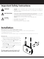
Mounting the Hub
a. Determine whether you are going to wall mount the hub.
ii. If hub is to be placed on bench, simply connect to power
supply, turn on and proceed to installing the Transceiver.
iii. If hub is to be wall mounted follow steps below.
d. To wall mount - Use wall bracket
3
as template to mark
where to drill holes. Pre-drill holes.
i. For plaster walls - insert (2) two Plastic wall plugs into holes,
place wall bracket over holes and affix with (2) two self
tapping screws
5
.
ii. For brick walls - place wall bracket
3
over holes and affix
with (2) two self tapping screws
5
.
c. Slide the hub
1
over the bracket.
d. Connect the power supply and turn on.
1
3
5
This device must be connected to power at all
times. DO NOT disconnect power after setup.
Before going out to site, check the following with the customer:
a. The customer has a Smart Phone: Android (running 4.4 and above) or IPhone (running iOS8 and above)
b. An internet connection for remote operation is available.
c. A 2.4ghz WiFi network is set up.
d. We recommend the customer has a WPA2 encryption on the WiFi network as other network types are not as secure.
Installation
Important Safety Instructions
WARNING!
• DO NOT attempt to disassemble, repair or modify the product. This will invalidate the
warranty.
• Do not allow children to play with the Base Station or your smart phone if the ATA phone
app has been installed.
ELECTROCUTION!
• Keep the device away from water and other liquids. In the event that water or other liquids
enter the device, power off he product immediately and clean the device.
• To reduce the risk of fire or electric shock, do not expose this device to rain or moisture. The
device should not be exposed to dripping or splashing.
• DO NOT remove the cover as there are no user-serviceable parts inside.
CAUTION:
Fall from ladder • Ensure ladder is the correct type for job.
• Ensure ladder is on flat ground.
• Ensure user has 3 points of contact while on ladder.

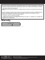
Roller Door Opener Set Up
Preparation of Opener
a. Disconnect the power supply to the opener.
b. Remove the light diffuser via screw at the bottom.
c. Remove the grommet out of the back cover.
d. Cut (1) one side of the grommet with a knife or scissors.
e. Slide the network timing harness
2
into the cut in the
grommet.
f. Refit grommet to back cover by sliding the harness
through hole before fitting grommet.
g. Connect the harness to the network pin on the control
board.
h. Refit the light diffuser.
Mount and connect Transceiver
a. Plug the other end of the harness into the transceiver
1
.
b. Place the transceiver
1
on the side of the opener to
the black, back cover so that the screw holes on the
transceiver line up with those on the back cover.
c. Secure transceiver using the (2) two Taptite M4 x 12
screws
3
or velcro
4
.
Re-setup and Test the Opener
a. Reconnect power and remove the button cover.
b. Setting Limits:
i. If limits have not been set, follow the openers
installation sheet to set limits.
ii. If limits were set previously, clear limits and follow
openers installation sheet to set limits.
c. Refer to the Smart Phone Control Kit User Guide to set up
network capabilities.
2
1
1
Network Pin
Light diffuser
Grommet
Light diffuser
screw
Aerial slot
Affix with screw here
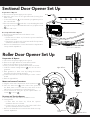
Preparation of Opener
a. Disconnect the power supply to the opener.
b. Open the side cover on the right hand side (looking from
back of unit).
c. Connect the harness
2
to the network / programmer pin on
the control board.
d. Place the transceiver
1
inside the cover, threading the aerial
through the slot provided and affix with one (1) Taptite Screw
3
.
e. Refit the side cover.
Re-setup and Test the Opener
a. Reconnect power and remove the button cover.
b. Setting Limits:
i. If limits have not been set, follow the openers installation
sheet to set limits.
ii. If limits were set previously, clear limits and follow operators
installation manual to set limits.
c. Refer to the Smart Phone Control Kit Quick Set Up Guide to
set up network capabilities.
1
3
2
NOT available with AM-800
(optional for AM-808)
Sectional Door Opener Set Up

Automatic Technology America
VIneyard Centre II, 1452 Hughes Road, Grapevine, Texas 76051, United States of America
P: +1 817 873 5076 W: www.automatictechnology.com
This device contains licence-exempt transmitter(s)/receiver(s) that comply with Innovation, Science and
Economic Development Canada’s licence-exempt RSS(s). Operation is subject to the following two conditions:
1. This device may not cause interference.
2. This device must accept any interference, including interference that may cause undesired operation of the
device.
L’émetteur/récepteur exempt de licence contenu dans le présent appareil est conforme aux CNR d’Innovation,
Sciences et Développement économique Canada applicables aux appareils radio exempts de licence.
L’exploitation est autorisée aux deux conditions suivantes :
1. L’appareil ne doit pas produire de brouillage;
2. L’appareil doit accepter tout brouillage radioélectrique subi, même si le brouillage est susceptible d’en
compromettre le fonctionnement.
Warranty
WARRANTY PERIOD
ACCESSORIES 1 Year
This Warranty is to be read in conjuction with the owner’s copy of the operator installation instruction
-
 1
1
-
 2
2
-
 3
3
-
 4
4


Automatic Technology Smart Phone Control Guide d'installation
- Taper
- Guide d'installation
dans d''autres langues
Autres documents
-
Genie 4164 Mode d'emploi
-
-
NuTone NGD00Z Guide d'installation
-
-
Genie 7033 Maintenance Manual
-
Quantum 3314 Owner Installation And User Manual
-
Ryobi GDM610 Manuel utilisateur
-
 Overhead door 2029 Programming And Operating Manual
-
Chamberlain RJO70 Manuel utilisateur
-
