Quantum 3314 Owner Installation And User Manual
- Catégorie
- Porte de garage
- Taper
- Owner Installation And User Manual

TM
OWNER INSTALLATION AND
USER MANUAL Series 3000
Models 3214, 3314, 3316 & 3414
Automatic Garage Door Opener
For Sectional Overhead Residential Doors Only
DO NOT USE ON ONE PIECE DOORS
CONTENTS
Installation
…................
2 Wireless Keyless Entry Installation
.....
20
Features
………………..
4 Opening & Closing Force Adjustment
…
21
Door Tests
………..........
5 Contact Obstruction Sensing Adjustment
.
22
Pre-Assembly Check
………….
5 Mechanical lock Adjustment
.........
22
Installation Instructions
…………
6 Operational Safety Rules
………
23
Installing Wall Station
……….…
8 Operation on Your Opener
……….
24
Install Infrared Safety Sensors
…….
9 Emergency Release Disconnect
......
26
Wall Station Code Change Maintenance Schedule
………...
27
and Programming
………….
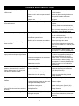
14 Trouble Shooting
……………
28
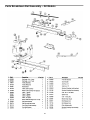
Infrared Safety Sensors Alignment 16 Parts Breakdown-Rail Assembly
……
29
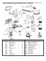
Transmitter Code Change & Programming 16 Parts Breakdown-Power Head Assembly
.
30
Travel Adjustment
……………
19 Accessories
……………...
31
Obstruction Sensing Test
……...
18 Warranty.
…………….....
32
Infrared Safety Sensor Obstruction Test
.
19
© Copyright 2003 Wayne-Dalton Corp. Part No: 307545 New 6/18/2003
DOOR AND OPENER WILL NOT OPERATE PROPERLY UNTIL INFRARED SAFETY
SENSORS ARE INSTALLED AND PROPERLY ADJUSTED! DO NOT OPERATE DOOR
OPENER UNTIL FULLY INSTALLED, ADJUSTED & INSTRUCTED TO DO SO!
Before Starting Installation Read all Instructions Thoroughly
to Familiarize Yourself with All As
p
ects of Installation and Ad
j
ustment!

2
Read These Important Safety Rules Before Proceeding
IMPORTANT INSTALLATION INSTRUCTIONS
WARNING: To reduce the risk of severe injury of death:
READ AND FOLLOW ALL INSTALLATION IN-
STRUCTIONS.
Install only on a properly balanced garage door.
An improperly balanced door could cause severe
injury. Have a qualified service person make re-
pairs to cables, spring assemblies and other
hardware before installing opener.
To reduce the risk of injury to persons, use this
operator only with sectional overhead doors.
Fiberglass, aluminum and steel doors must be re-
inforced to prevent damage to the door. Check
with your garage door manufacturer for their rec-
ommendations.
Remove all ropes and remove or make inoperative
all locks connected to the garage door before in-
stalling opener.
Do not use sensitivity adjustments to compensate
for a poorly operating door. This will interfere
with the proper operation of the safety reverse
mechanism and may damage the door.
Locate control button: within sight of door, at a
minimum height of 5 feet, so small children can-
not reach it, and away from all moving parts of the
door.
If possible, install door opener 7 feet or more
above floor. Mount the emergency release knob 6
feet above the floor.
Do not connect opener to source of power until
instructed to do so.
Installation and wiring must comply with local
building and electrical codes. Connect the power
cord to a properly grounded outlet. Do not re-
move round ground pin from power cord.
Install entrapment warning label next to control
button in a prominent location, such as the inside
of the garage door, or as instructed in the installa-
tion instructions. If label adhesive will not adhere
to the surface, secure the label by additional me-
chanical means such as staples, nails or screws.
If necessary, use an intermediate mounting sur-
face, such as plywood, cut to the appropriate size.
Install Emergency Release tag to the emergency
red cord.
After installing opener, the door must reverse
when it contacts a 1 inch high solid test object on
the floor.
Open door must not close and closing door must
open if photoelectric system in obstructed by 6” x
12” object, using test procedure described in Step
30.
Do not wear rings, watches or loose clothing
when installing or servicing a garage door sys-
tem. Use a sturdy, non-metallic step ladder.
AFTER INSTALLATION IS COMPLETE, FASTEN THIS MANUAL NEAR GARAGE DOOR.
PERFORM PERIODIC SAFETY CHECKS, MAINTENANCE AND ADJUSTMENTS, AS RECOMMENDED.
NOTE: This equipment has been tested and found to comply with the limits for a Class B digital device, pursuant to Part 15 of the FCC Rules.
These limits are designed to provide reasonable protection against harmful interference in a residential installation. This equipment gener-
ates uses and can radiate radio frequency energy and, if not installed and used in accordance with the instructions, may cause harmful inter-
ference to radio communications. However, there is no guarantee that interference will not occur in a particular installation. If this equipment
does cause harmful interference to radio or television reception, which can be determined by turning the equipment off and on, the user is
encouraged to try to correct the interference by one or more of the following measures: Reorient or relocate the receiving antenna. Increase
the separation between the equipment and receiver. Connect the equipment into an outlet on a circuit different from that to which the receiver
is connected. Consult the dealer or an experienced radio/TV technician for help. Warning: Changes or modifications to this unit not ex-
pressly approved by Wayne-Dalton Corp. could void the user’s authority to operate the equipment.
FCC Regulatory Information: This device complies with Part 15 of the FCC Rules. Operation is subject to the following two conditions: (1)
this device may not cause harmful interference, and (2) this device must accept any interference received, including interference that may
cause undesired operation.
IC Regulatory Information: This Class B digital apparatus meets all requirements of the Canadian Interference Causing Equipment Regula-
tions. Operation is subject to the following two conditions: (1) this device may not cause harmful interference, and (2) this device must ac-
cept any interference received, including interference that may cause undesired operation.
This symbol indicates caution and appears throughout this instruction
manual. This garage door opener is designed and tested to offer reasona-
bly safe operation if installation is followed in strict accordance with these
safety instructions. Failure to comply with these instructions may result in
serious personal injury or property damage.

3
Veuillez lire ces règles de sécurité importantes avant de commencer les travaux
IMPORTANT —NOTICE D’INSTALLATION—
AVERTISSEMENT –POUR REDUIRE LES RISQUES DE BLESSURES MORTELLES
LISEZ CETTE NOTICE ET CONFORMEZ-VOUS AUX
INSTRUCTIONS.
NE POSEZ CET OUVRE-PORTE QUE SUR UNE
PORTE DE GARAGE CORRECTEMENT ÉQUILI-
BRÉE. UNE PORTE MAL ÉQUILIBRÉE PEUT CAU-
SER DES BLESSURES GRAVES. CONFIEZ LA RE-
PARATION DES CABLES, DES RESSORTS, ET DE
TOUT AUTRE ÉLÉMENT À UN TECHNICIEN QUALI-
FIÉ AVANT D’ENTREPRENDRE L’INSTALLATION.
POUR RÉDUIRE LE RISQUE DE BLESSURES COR-
PORELLES, UTILISER CET OUVRE-PORTE POUR
DES PORTES BASCULANTES SECTIONNELLES
UNIQUEMENT.
LES PORTES EN FIBRE DE VERRE, EN ALUMINUM
ET EN ACIER DOIVENT ETRE RENFORCÉES POUR
EVITER D’ENDOMMAGER LA PORTE. CONSULTEZ
LE FABRICANT DE VOTRE PORTE DE GARAGE
POUR OBTENIR SES RECOMMANDATIONS.
ENLEVEZ LES CORDES ET ENLEVEZ OU NEUTRA-
LISEZ TOUT DISPOSITIF DE VERROUILLAGE SOLI-
DAIRE DE LA PORTE DE GARAGE AVANT
L’INSTALLATION.
NE VOUS SERVEZ PAS DES RÉGLAGES DE LA
SENSIBILITÉ POUR COMPENSER LE MAUVAIS
FONCTIONNEMENT D’UNE PORTE. CECI POUR-
RAIT FAIRE OBSTACLE AU BON FONCTIONNE-
MENT DU MÉCANISME DE L’INVERSEUR DE SÉ-
CURITÉ ET POURRAIT ENDOMMAGER LA PORTE.,
DANS LA MESURE DU POSSIBLE, INSTALLEZ
L’OUVRE-PORTE Á AU MOINS 2.14M (7PI) DU SOL.
POSEZ LE DISPOSITIF DE DÉSACCOUPLEMENT
D’URGENCE Á 1.83 M (6 PI) DU SOL.
INSTALLEZ LE BOUTON DE COMMANDE
Á UN EN-
DROIT QUE L’ON PEUT VOIR DE L’EMBRASURE DE
LA PORTE,
À UNE HAUTEUR MINIMALE DE 1.53 M
(5 PI) DU SOL –AFIN QUE LES JEUNES ENFANTS
NE PUISSENT PAS L’ATTEINDRE—ET
À L’ENCART
DES PIECES MOBILES DE LA PORTE.
APPOSEZ L’ÉTIQUETTE DE MISE EN GARDE RE-
LATIVE AU DANGER DE HAPPEMENT À PROXIMITE
DU BOUTON DE COMMANDE ET L’ÉTIQUETTE RE-
LATIVE AU RÉGLAGE DE LA COMMANCE Á UN
EMPLACEMENT EN EVIDENCE—PAR EXEMPLE
SUR LA PAROI INTÉRIEURE DE LA PORTE DE GA-
RAGE OU SELON LES INSTRUCTIONS DE LA NO-
TICE D’INSTALLATION. APPOSEZ L’ÉTIQUETTE
RELATIVE AU DÉSACCOUPLEMENT D’URGENCE
SUR LE DISPOSITIF OU À PROXIMITE DE CE DER-
NIER.
NE BRANCHEZ PAS L’OUVRE-PORTE AVANT D’Y
ÊTRE AUTORISÉ PAR LA NOTICE.
UNE FOIS L’OUVRE-PORTE INSTALLÉ, LES SENS
DE LA COURSE DOIT S’INVERSER LORSQUE LA
PORTE ENTRE EN CONTACT AVEC UN OBJET
D’UNE HAUTEUR DE 25.4MM (1 PO) POSE SUR LE
SOL.
L’INSTALLATION ET LE BRANCHEMENT ÉLECTRI-
QUE DOIVENT ÊTRE CONFORMES AUX CODES
LOCAUX DU BÂTIMENT ET DE L’ÉLECTRICITÉ
RACCORDER LE CORDON D’ALIMENTATION
Á
UNE PRISE ADÉQUATEMENT MISE Á LA TERRE.
NE PAS ENLEVER LA BRANCHE RONDE DE MISE Á
LA TERRE DU CORDON D’ALIMENTATION.
SI LE SYSTÈME PHOTOÉLECTRIQUE EST BLOQUÉ
PAR UN OBJET DE PLUS DE 6 PO X 12 PO, LA
PORTE OUVERTE NE DOIT PAS SE FERMER ET LA
PORTE SE FERMANT DOIT S’OUVRIR. VÉRIFIER
CELA EN UTILISANT LA VÉRIFICATION DÉCRITE
Á
L’ÉTAPE 20.
NE PAS PORTER DES BAGUES, DES MONTRES OU
DES VÊTEMENTS LÂCHES PENDANT
L’INSTALLATION OU LA VERIFICATION TECHNI-
QUE DU SYSTÈME DE PORTE DE GARAGE. UTILI-
SER UNE ÉCHELLE NON MÉTALLIQUE STABLE.
CONSERVEZ CES INSTRUCTIONS.
"Cet appareillage numérique de la classe B répond à toutes les exigences de l’interférence canadienne causant des règlements
d’équipement. Ľopération est sujette aux deux conditions suivantes: (1) cet dispositif peut ne pas causer l’interférence nocive, et (2) ce dis-
positif doit accepter n’importe quelle interférence reçue, y compris l’interférence qui peut causer l’opération peu désirée. "
Ce symbole vous demande de prendre les précautions voulues. Vous le trouverez d’un bout à
l’autre du présent guide d’installation. Cet ouvre porte de garage a été conçu et essaye pour
vous offrir un fonctionnement sécuritaire dans la mesure ou les directives d’installation sont
respectées conformément a ces mesures de sécurité. Le non respect de ces mesures de
sécurité risqué d’entraîner des blessures corporelles graves et des dommages matériel.
APRÈS L’INSTALLATION, PLACER CE MANUEL À PROXIMITÉ DE LA PORTE DE GARAGE FAIRE RÉ-
GULIÈREMENT LES VÉRIFICATIONS RECOMMANDÉES CONCERNANT LA SÉCURITÉ L’ENTRETIEN
ET LES RÉGLAGES

4
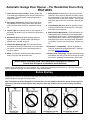
Automatic Garage Door Opener – For Residential Doors Only
FEATURES
1. Open and Close Cycle Control: Allows garage door
to be started and stopped by push button, transmitter or
wall station. The next impulse sends garage door in
opposite direction.
2. Emergency Disconnect: Manual disconnect permit-
ting operation of door during power failure with auto-
matic reconnect when opener is reactivated. See pg
26.
3. Opener light: Automatically turns on when opener is
activated and remains on for 4 minutes for convenience
and safety.
4. Mechanical Door Lock: When properly adjusted,
opener locks door in closed position preventing un-
wanted entry. See Adj. # 3 pg 22.
5. Obstruction Warning Light: The convenience light
will flash after sensing an obstruction in the down direc-
tion and/or if the safety system malfunctions while in
the open position.
6. Motor: Permanently lubricated, thermally protected,
heavy duty motor with automatic reset.
7. Safety System: Independent up and down force ad-
justments. When properly adjusted, the safety system
will automatically reverse when obstructed in down di-
rection and return to fully open position. The door will
stop when obstructed in the up direction. See Adj. #2,
pg 22.
8. Infrared Safety Sensors: Wired or wireless infrared
reversing sensors detect an obstruction in door path
and react by reversing door.
9. Multi-Function Wall Station: Wired wall station pro-
vides up/down door motion control and independent
overhead light on/off control. Wireless wall station pro-
vides up/down door motion control, independent over-
head light on/off control, door down delay, adjustable
“pet position” function, and “pet position” program but-
ton.
10. Homelink™ Compatibility: Opener is capable of
“learning” automobile equipped Homelink™ transceiv-
ers. Visit: www.homelink.com.
11. Rolling Code Technology: Wireless transmitters and
wall stations use rolling code which prevents would-be
thieves from “grabbing” the transmitter’s digital code.
Caution: If your garage has no service entrance door, install optional outside quick release lock. This accessory allows
manual operation of garage door from outside in case of power failure.
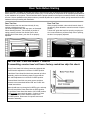
Identify the door referring to illustrations below and verify that the door type is a sectional door with curved track. Do not
install if the door is any type of one piece door.
Note: The opener has been designed for sectional doors. Do not attempt to install this opener on any style one
piece door. Use of the enclosed opener on a one-piece door may result in serious personal injury of property
damage.
Before Starting Installation Read These Instructions Thoroughly to Familiarize
Yourself with All Aspects of Installation and Adjustment!
Before Starting

5
IMPORTANT PRE-ASSEMBLY CHECK
If assembling a motor head unit from a factory sealed box skip this check.
Every Power Head Unit is factory tested and shipped with
the limit switch adjustment in the door CLOSED position.
If the Motor Power Head Unit has been powered up before
assembly, perform the following steps to insure that the
limit switch adjustment is in the door CLOSED position.
Connect Motor Head Unit to a power source and short
across the screw terminals labeled “PB” and “COM” with
a metal screw driver.
Motor should start; run through a full OPEN cycle, and stop.
This will leave Motor Power Head Unit in OPEN position.
To get Motor Power Head Unit back to full CLOSE position,
short and hold
motor terminals again. Continue to short
terminals until Motor Power Head Unit stops in the
CLOSED position. Disconnect from power source and
proceed to assembly.
Before you begin, complete the following two tests to insure that the door is balanced and working properly. A door that
binds, sticks or is out of balance could cause severe injury. Do not attempt to compensate for an improperly adjusted door
by the installation of an opener. This will interfere with the proper operation of the opener mechanism and/or may damage
the door. Have a qualified service person make any needed adjustments or repairs to cables, spring assemblies and other
hardware before proceeding with installation.
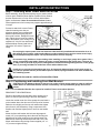
Door Test One
Raise and lower the door and check closely for any
sticking or binding that occurs.
Lift the door approximately half way open, as illustrated.
When releasing the door, it should stay in position. If
spring pressure pulls the door further open or door
weight pulls it further down, your door is not properly
adjusted.
Door Test Two
When properly installed, a door should remain clear of
the opening, when allowed to rest at its natural, full open
position.
If “door drift” pulls door back into opening or spring ten-
sion is not sufficient to pull door totally clear of opening,
the door is not properly adjusted.
Door Tests Before Starting

6
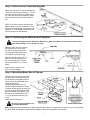
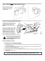
Step 1: Attaching Motor Power Head Unit to Rail
Before assembly, align sprocket/coupling cogs to match notches
of driver gear. Rotate the Motor Spline to position Driver Gear so
that the nearest notch in Driver Gear is directly behind Motor
Spline, as illustrated. Note: Do not rotate more than ½ turn.
Place opposite end of rail on temporary support approximately 6”
in height.
Proceed to attach rail to motor Power
Head Unit making sure that pre-
alignment allows proper engagement
between sprocket/coupling cog and
driver gear notches. Realign as neces-
sary, making sure to keep any rotation
only to the nearest notch. Using four (4)
supplied 1/4”-20 x 5/8” hex head bolts,
assemble Motor Power Head Unit to
rails with a 3/8” socket. Tighten se-
curely.
Do not plug the opener power cord into electrical outlet until fully installed and instructed to do so in
this manual. Door springs, pulleys and cables are under extreme tension and can cause severe injury.
Do not attempt to adjust or repair. Call a professional door service company.
Do not wear rings, watches or loose clothing when installing or servicing a garage door system. Use a
sturdy, non-metallic step ladder. Remove all ropes or cords attached to the garage door. Failure to do
so may result in personal injury due to entanglement. Disable all existing locking devices on the garage
door, by securing lock/latch to inside face of door with suitable screw.
Install only on a properly balanced garage door. An improperly balanced door could cause severe in-
jury. Have a qualified service person make repairs to cables, spring assemblies and other hardware be-
fore installing opener.
READ AND FOLLOW ALL INSTALLATION INSTRUCTIONS
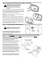
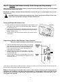
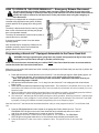
Step 2: Positioning and Installing Front Wall Bracket
CAUTION: Do not attempt to loosen or remove any portion of door spring system in order to reinforce
header wall or to mount wall bracket. If these are necessary, call a professional garage door service
person.
Note: it is recommended that the door opener be installed 7 feet or more above the door.
REINFORCE THE HEADER WALL
Reinforce the header wall (wall above door opening) as re-
quired, to ensure rigid mounting of the front wall bracket.
Locate the vertical center line of the garage door and mark it
on the header above the door and on the top rail of the door.
Raise the door slightly until the top rail reaches the highest
point of travel (see illustration); using a carpenter’s level,
transfer and mark the highest point of travel on the header
wall.
Mount the front wall bracket with its lower edge approxi-
mately 1/2” (room permitting) above the mark showing the
highest point of travel centered on the vertical center line.
Mark the two mounting holes and pre-drill with a 3/16” drill.
Mount wall bracket using the lag screws supplied (1/4” x 1-
1/2”) to ensure rigid mounting.
INSTALLATION INSTRUCTIONS

7
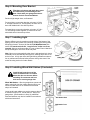
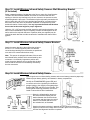
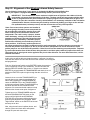
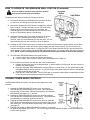
Step 3: Attach Unit to Front Wall Bracket
Raise the front end of the opener and attach it
to the front wall bracket, using the ¼” x 4” hex
head bolt and the supplied ¼” plastic insert
nut. Take care not to over tighten nut; tighten
only until end of bolt is flush with outside of
nut.
NOTE: If you have a torsion spring counter-
balance system, it will be necessary to raise
the motor Head Assembly of the opener and
support it on a step-ladder to attach the front
end of the opener to Wall Bracket.
Step 4: Positioning the Motor End of Operator
To prevent damage to steel, aluminum, fiberglass or glass panel doors do not rest the opener of the
door without using a 2” x 4” at least 12” long.
Raise the motor end of the opener
and support it so you can open
the door to its fully open position.
You may need help raising motor
end if ladder is not high enough.
Open the door and place a 2” x 4”
piece of wood along the top sec-
tion of the garage door. Rest the
double rails on the 2” x 4”, as illus-
trated.
Support the top section of the
door to prevent sagging.
Step 5: Mounting Motor End of Opener
Align the center of opener tracks with
the center line previously marked on
the top section of the garage door to
ensure rail will be parallel with the di-
rection of door travel.
Use perforated hangers (cut as
needed to adjust length) from ceiling
or beams to hang opener at motor end
(be sure to locate and mount to solid
structural beams, as illustrated). Pre-
drill with 3/16” drill bit and use 1/4” x
1-1/2” lag screws to ensure a rigid
mount.
Attach opener to hangers.
Do not use gear cap bolt or nut
for hanger attachment!
Note: Hanging brackets should be at an angle to provide rigid support. If hangers have no angle or if you use long hang-
ers, cross brace the hangers to eliminate the possibility of sway during operation of the opener.

8
Step 6: Mounting Door Bracket
Fiberglass, aluminum and steel doors must
be reinforced to prevent damage to the
door. Check with your garage door manu-
facturer for their recommendations.
Reinforce light weight doors, as illustrated.
For wood doors, mount door bracket, using two 1/4”-20 x
2” carriage bolts and 1/4” nuts supplied, on center line of
door with middle hole in line with top rollers.
For metal doors, mount door bracket, using two 1/4”-20 x
1/2” self drilling screws supplied, on center line of door
with middle hole in line with top rollers.
Step 7: Installing Light
Remove diffuser cover by pressing on both sides of the bottom of the
lighting cover at the junction of the housing, releasing the locking tabs,
and pulling forward. Screw a 60 Watt bulb (60 Watt Maximum) into
socket. For maximum bulb life, “rough service” bulbs are recom-
mended. Align top and bottom tabs on cover to Motor Power Head Unit
and push straight on until cover locks into place.
Note: light turns on automatically when door is activated and a 4 minute
time delay circuit automatically turns light off, allowing ample time to en-
ter the house. A fully open door with light blinking indicates an obstruc-
tion or problems with external safety sensors during close travel. See
trouble shooting section for further details.
Step 8: Installing Wired Wall Station (if included)
Install all wall controls out of the
reach of children and in a location
where the door can be seen before
activating. Do not mount wall con-
trols near or next to garage door.
Wired Wall Station: Wire the garage door opener wall
station using bell wire (low voltage electrical wire) con-
nected to COM and P.B. on vertical screw terminal
strips, as illustrated.
Locate push button adjacent to service entrance door at
a minimum height of 5 ft., and at least 5 ft. away from
garage door; (see illustration in Step 10); additional
wired wall stations may also be installed in accordance
with these instructions.

9
Step 9: Installing Deluxe Wireless Wall Station (if included)
Install all wall controls out of the reach of
children and in a location where the door
can be seen before activating. Do not
mount push buttons near or next to ga-
rage door.
Locate a convenient place to mount wall station. To keep wall sta-
tion out of the reach of children, measure at least five feet up from
the floor and secure wall station base into wood wall framing using
(2) Phillips head screws. Pilot drill mounting holes using a 3/32" bit.
Use 2 of 3 holes that best align with wood framing.
CAUTION: Over tightening the screws could deform plastic base
and interfere with circuit board snaps.
NOTE: Insert bottom of circuit board behind bottom snap of wall
station base. Pivot circuit board up until board snaps into place.
For best results, press on circuit board between battery terminals.
Insert battery onto circuit board being careful to match (+) positive
battery marking with (+) circuit board marking. Align wall station
cover/button assembly with base. Press cover assembly over base
until cover snaps into place. A uniform seam between the cover
and base indicates a proper installation.
Step 10: Install Entrapment Warning Label
Install Entrapment Warning Label next to
wall station in a prominent location
Install Entrapment Warning Label next to Wall Station as
illustrated. If label adhesive will not adhere to the sur-
face, secure the label by additional mechanical means
such as staples, nails or screws.
Step 11: Install Wireless Infrared Safety Sensor Quick-Install (QI) Mounting
Bracket.
(If Opener is Equipped with Wired Infrared Safety Sensor Go to Step 15)
Use the following instructions if your door tracks
come pre-punched for using QUICK-INSTALL
brackets otherwise go to step 12.
Each bracket is marked either L or R just below the
slide lock. (L & R refers to left and right side of ga-
rage door as viewed from inside the garage).
Start with the right side bracket as illustrated. Slip
the Slide Lock tab of the QI bracket into the door
track mounting slot near the bottom of the door
track. Slide the bracket downward until it seats at the
bottom of the slot. Repeat the same step for the left
vertical track using the left Quick Install Bracket. You
should encounter some resistance when pushing
down on the QI-bracket. If needed, use a flat blade
screwdriver against the top edge of the bracket and
gently tap into position with a hammer.
NOTE: It is very important that both brackets are
mounted at the same height so sensors align.

10
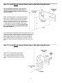
Step 12: Install Wireless Infrared Safety Sensors Wall Mounting Bracket
(If Included)
Select a mounting position 5 inches above the floor to center line of wall bracket.
The EMITTER and TRANSPONDER units must be mounted inside the door
opening to minimize any interference by the sun; however, the sensors must be
mounted against the door track. The brackets may be temporarily mounted to the
wall (or jamb) with a #8 X1/2” screw provided and should be in contact with the
door track. Leave this screw in place after installation is completed to prevent
accidental rotation of beam sensor. It is very important that both wall brackets
be mounted at the same height for proper alignment.
Using the 1/4” x 3/4” lag screw provided, attach the wall mounting bracket to the
wall. In some installations it may be necessary to attach wooden spacers to the
wall to achieve the required clearance. Expansion bolts (not supplied) may be
required to attach brackets to walls constructed of materials other than wood or
gypsum.
Step 13: Install Wireless Infrared Safety Sensor Bracket
Attach the sensor bracket to the wall bracket using the
two #8 x 1-1/2” screws supplied (make sure that the
curved hooks protruding from the bracket are positioned
over and in firm contact with the door track).
Note: This opener is equipped with state-of-the-art wire-
less infrared safety sensors which are activated by door
movement. It is extremely important to position and
mount the sensor brackets in firm contact with the door
track so that the sensors are immediately activated by
the door movement.
Step 14: Install Wireless Infrared Safety Sensor
Open hinged cover on infrared safety sensors and remove battery protective paper strip.
Observe proper battery polarity, as illustrated, in battery compartment.
Identify the TRANSPONDER (green LED) and
mount this unit on the right side (from inside the
garage looking to the outside) of the garage door
and the EMITTER (red LED) on the left side. This
same right/left mounting procedure must be fol-
lowed on two and three door installations.
Mount the infrared safety sensors to
the sensor bracket keeping the soft
washer between the sensor and sen-
sor bracket and then place the conical
washer, lock washer and hex nut on
the extender bolt, as illustrated.
Keeping the sensors pointing in towards door and aimed at each other,
tighten nut until there is enough friction to hold in place. Do not fully tighten
until the final alignment has been completed.

11
Step 15: Install Wired Infrared Safety Sensor Wall Mounting Brackets
Use the following instructions if your opener is
equipped with Wired Infrared Safety Sensors. If
you just installed the Wireless Infrared Safety Sen-
sors go to step 20.
Select a mounting position 5 inches above the floor to
center line of wall bracket. The sending and receiving
units should be mounted inside the door opening to
minimize any interference by the sun. However, the
sensors should be mounted as close to the door track
or inside edge of the door as possible to offer maxi-
mum entrapment protection. It is very important that
both wall brackets be mounted at the same height
for proper alignment.
The brackets may be temporarily mounted to the jamb with a 1” flat
head nail (provided), permanently mount the wall mounting bracket
to both door jambs. In some installations it may be necessary to
attach wooden spacers to the wall to achieve the required clear-
ance. Expansion bolts (not included) may be required to attach
brackets to walls constructed of materials other than wood or gyp-
sum.
Step 16: Install Wired Infrared Safety Sensor Wall Mounting Brackets
Attach the “U” brackets to the wall brackets
with a 1/4 -20 carriage bolt, washer and hex
nut (provided). Insert the bolt from the inside
of the “U” bracket and hand tighten only at this
time.

12
Step 17: Install Wiring for Wired Infrared Safety Sensor
Identify which side of the garage
door opening (if any) the sun is
“likely” to shine on to. Since
sunlight may affect infrared safety
sensors, you should mount the
sending unit on the side of the
door opening exposed to the sun.
Uncoil the wires from the infrared
safety sensors and route the wire
up the garage wall across the ceil-
ing and down to the back of the
power head, as illustrated. Tack
the wires in place using staples.
Take care to run the wires in a
location where they will not inter-
fere with the operation of the door
and do not staple through wire. Be
sure to leave about 12” of excess
wire at each end so you will have
enough slack wire to mount units.
Note: If wires must be lengthened or spliced into pre-
wired installation, use wire nuts or a suitable connec-
tor.
Step 18: Connecting Wired Infrared Safety Sensor to Opener
Connect Infrared Safety Sensors to power head
as per diagram. Shorten the wires as necessary
and separate the wire ends. Strip about 1/2" of
insulation off each wire and attach the wires to
the proper terminal screws, then tighten se-
curely, using a small blade screwdriver.
One wire has marking on it (numbers, black
stripe, etc). Be sure to observe polarity. Apply
tension to external wires to test for secure con-
nection. Check that the wires are stapled in
place.

13
Step 19: Mount Wired Infrared Safety Sensors
Attach the sending and receiv-
ing units to the “U” brackets by
inserting their tabs into their
respective holes.
Step 20: Connecting Electrical Power
To reduce the risk of electrical shock,
connect the power cord only to a
properly grounded 3 prong, 120 volt
outlet.
Do not use an extension cord or change
the plug in any way. At this point, plug in
the opener to an electrical outlet. If the
plug does not fit into the outlet, or you
require permanent wiring, contact a
qualified electrician to install the proper
outlet. As soon as power is applied to
the unit, the light on the opener will blink
once to indicate a successful self-check of the controls.
Check your local electrical codes. If your
local code requires permanent wiring,
use the specifications called for and in-
structions illustrated.
Permanent Wiring Procedure
1. Ensure line cord is disconnected from power source.
2. Cut line cord 1/2” – 1” from strain relief / bushing.
3. Use needle nose pliers to remove strain relief bushing from frame. Squeeze tabs in on underside of bushing and
work bushing out of hole.
4. Pull or strip off remaining section of outer insulation from three conductors of line cord. Pull the three wires into
the operator. Discard remaining line cord.
5. Strip 1/2" of insulation from the black, white, and green wires.
6. Using UL/CSA approved wire nuts for 14-18AWG wire, wire nut black-black, white-white, and green-green (earth)
wires securely.
7. Replace Power Head Unit cover.
DO NOT USE AN ELECTRICAL EXTENSION CORD OF ANY TYPE

14
Step 21: Wireless Wall Station Security Code Change and Programming
Note: The following steps describe the process to change the Wireless Wall Station security code and to program
the Wireless Wall Station to the opener.
IMPORTANT: You MUST change the Wireless Wall Station security code prior to programming the device to the
power head unit.
WARNING: During programming the garage door may operate. Keep people and objects clear of the
moving door to prevent door damage or possible personal injury.
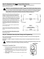
Changing Wireless Wall Station Code
1. Press and hold the wall station’s light button for approximately 10 sec-
onds until the wall station’s LED begins to blink rapidly. Release but-
ton (LED will turn off).
2. Press and hold the wall station’s light button again (LED will light) for
approximately 5 seconds until the wall station’s LED begins to blink
rapidly. Release button.
3. LED will blink on and off three times indicating a successful security
code change.
Programming Wireless Wall Station to Power Head Unit
Note: Do not press any button on the wall station until instructed
1. Press the PROGRAM Switch button located on the garage
door power head unit once. The red PROGRAM STATUS
light on the motor power head unit and overhead lamp will
turn on and remain lit for one minute, indicating that it is
ready to learn the wall station.
2. Press the light on/off button on the wall station. The PRO-
GRAM STATUS light will turn on and off three times indicat-
ing a successful learn.
3. Press the light on/off button on the wall station once more to
confirm operation. The overhead light will toggle from on to
off and from off to on.
At this point you will be able to activate the opener. It will open, but will not close the door. Before unit will close door the
beam sensors must be aligned and programmed (next step).
Battery: If the LED (light) on wall station does not turn on when a button is pressed, repeat “changing wireless
wall station code” operation. If LED fails to light replace battery. To change battery, insert a coin in the coin slot
and twist coin to access battery compartment. Replace battery with a single MN21 or equivalent battery. Snap
case together after replacing.

15
Step 22: Alignment of the Wireless Infrared Safety Sensors
Use the following instructions if your opener is equipped with Wireless Infrared Safety Sen-
sors. If your opener is equipped with Wired Infrared Safety Sensors proceed to step 23.
IMPORTANT: This infrared beam sensor sends an invisible beam of light from the emitter unit to the
transponder unit across from the pathway of the door. The door opener will not operate until the safety
sensor is programmed to the power head and it is properly aligned. If the invisible beam of light is ob-
structed, an open door cannot be closed by the transmitter or a momentary activation of the wall station
up/down button. However, the door may be closed by continuously holding your finger on the wall sta-
tion up/down button (constant pressure) until the door travels to a fully closed position.
Note: If two or more door openers are installed in
the same garage, the safety sensor transponder for
the second and/or third doors must be set to a dif-
ferent code to prevent interference with the first
transponder. The code is set by a jumper, located
under the battery, closest to the center of the com-
partment, as illustrated. The code jumper has three
positions (A-B-C), selected by a moveable jumper,
and has been randomly set at the factory to one of
these positions. If the factory random selection of
the jumper position has resulted in a different code for each transponder, no further changes are necessary. If
not, note the position of the jumper (A, B or C) on the first door transponder and set the second door trans-
ponder jumper to one of the other two positions. A third door will use the remaining un-used position. Temporar-
ily remove the batteries from all but the door being worked on and then replace when all jumpers have been set.
The jumper has no polarity and can be applied to the pins in either direction. For more than three doors, call for
technical assistance.
At this point you will be able to activate the opener. It will open, but will not
close the door. Before unit will close door the beam sensors must be aligned
and programmed.
First, the “Align-Normal” switch on the EMITTER (under the protective
cover) must be set to Align. (See illustration). This should cause the
adjacent RED LED indicator light to turn on. Check to see that the
EMITTER is pointed toward the TRANSPONDER and that the hex nut
holding the EMITTER in place is tight enough that the unit will not
move.
Loosen the hex nut on the TRANSPONDER just
enough that you can rotate it up and down and
side to side. Rotating the TRANSPONDER will
cause the GREEN LED on the TRANSPONDER
to blink when aligned. Rotate TRANSPONDER up
and down and side to side to determine best
alignment. We recommend wide rotations to help
determine the closest center point of alignment.
Tighten hex nut on TRANSPONDER and push
and hold PROGRAM SWITCH button on the
opener until the light bulb and PROGRAM
STATUS LED on the opener blinks showing pro-
gramming and alignment are completed. Reset
“Align-Normal” switch on the EMITTER to Normal
and snap cover shut.
Now, using the wall control up/down button, acti-
vate the opener and check that it will operate
through full open and close cycles.

16
Step 23: Alignment of the Wired Infrared Safety Sensors
Use the following instructions if your opener is equipped with Wired Infrared Safety Sensors.
Otherwise proceed to step 24.
IMPORTANT: This infrared beam sensor sends an invisible beam of light from the sending unit to the
receiver unit across from the pathway of the door. The door opener will not operate until the safety sen-
sor is connected to the power head and properly aligned. If the invisible beam of light is obstructed, an
open door cannot be closed by the transmitter or a momentary activation of the wall station up/down
button. However, the door may be closed by continuously holding your finger on the wall station
up/down button (constant pressure) until the door travels to a fully closed position.
At this point you will be able to activate the opener; it
will open, but will not close the door unless the beam
is aligned. The beam sensors must be aligned by
moving the sending and receiving units in or out (see
Figure 1) until the alignment light on the receiving unit
comes on. The 1/4"-20 carriage bolt can be loosened
to move the unit in or out, as required. If you have dif-
ficulty aligning beams, check that both brackets are
mounted at the same height (see Step 9) and remount
if necessary. Additional minor adjustments can be
made by lightly bending the mounting brackets (see
Figure 2).
Once the alignment light comes on, tighten all bolts
and mounting screws.
Finish securing all wire making sure not to break or
open any of the conductors. Loop and secure any ex-
tra wire.
Now, using the wall station up/down button, activate
the opener and check that it will operate through full
open and close cycles.
Step 24: Transmitter Security Code Change and Programming
Note: The following steps describe the process to change the Transmitter security code and to program the
Transmitter to the opener.
IMPORTANT: You MUST change the Transmitter security code prior to programming the device to the power
head unit.
WARNING: During programming the garage door may operate. Keep people and objects clear of the
moving door to prevent door damage or possible personal injury.
Changing the Transmitter Code
1. Press and hold the Transmitter’s large button for approximately 10
seconds until Transmitter’s LED begins to blink rapidly. Release but-
ton (LED will turn off).
2. Press and hold the Transmitter’s large button again (LED will light) for
approximately 5 seconds until the Transmitter’s LED begins to blink
rapidly. Release button.
3. LED will blink on and off three times indicating a successful security
code change.

17
Programming Transmitter to Power Head Unit
Note: Do not press any button on the Transmitter until instructed
1. Press the PROGRAM Switch button located on the garage door
power head unit once. The red PROGRAM STATUS light on the
motor power head unit and overhead lamp will turn on and
remain lit for one minute, indicating that it is ready to learn the
Transmitter.
2. Press the button on the Transmitter you wish to use to operate
the door. The PROGRAM STATUS light on the power head will
turn on and off three times indicating a successful learn.
3. Press the same button on the Transmitter once more to confirm
operation. The opener will turn on and move the door.
At this point you will be able to activate the opener.
Battery: If the LED (light) on Transmitter does not turn on when a
button is pressed, repeat “changing the transmitter code” opera-
tion. If LED fails to light replace battery. To change battery, insert a coin
in the coin slot and twist coin to access battery compartment. Some
transmitters use two CR2016 or equivalent batteries while others use a
single MN21 or equivalent battery. Snap case together after replacing.
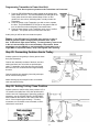
Step 25: Connecting Cushion Arm to Trolley
Activate opener to bring trolley to factory pre-set close
limit (See illustration).
Cushion arm assembly consists of the door arm tube
section and door arm rod, which are packed sepa-
rately. To assemble, screw the door arm rod into the
door arm tube in a clockwise direction approximately
ten turns.
Connect cushion arm assembly into trolley with open
end of rod hook facing motor.
Attach warning tag and red pull knob to red release
cord connected to trolley.
Step 26: Setting Trolley Close Position
Activate opener to confirm trolley close position is 9” to
10” between the inside face of the door and the solid
cushion arm rod. If adjustment of the trolley position is
necessary, use the CLOSE TRAVEL ADJUSTMENT
knob located on the bottom of the motor power head
unit. A 1/4 turn equals approximately 1” of trolley
movement; turn clockwise to move forward; counter-
clockwise to move back.

18
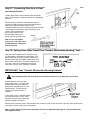
Step 27: Connecting Door Arm to Door
Door Mounted Bracket
Visually align cushion arm connecting hole with middle
hole of door bracket by rotating tube section in appropriate
direction.
Release trolley (cushion arm attached) with manual
release cord and pull trolley a few inches toward motor.
Now rotate cushion arm tube section 2 turns
counterclockwise to provide a cushion when door is closed
or encounters an obstruction. Align connecting hole in
cushion arm to middle hole in
door bracket; insert 3/8” dia.
bolt and tighten locking nut,
allowing for free pivoting of arm.
Note: Do not over tighten
locking nut, as this will cause
binding between cushion arm
and door bracket.
Step 28: Setting Door Close Travel Plus “Contact Obstruction Sensing” Test
With wall control up/down button, activate door to
full open position; reactivate to close position. The
door should stop on the floor with the cushion arm
and the bottom door seal slightly compressed. If the
door reverses off the floor, turn close travel knob 1/4
turn “less”. If door is not completely closed, turn
travel knob 1/4 turn “more”. Repeat if necessary.
IMPORTANT! Test “Contact Obstruction Sensing Feature”
After installing opener, the door must reverse when it contacts a 1 inch high object on the floor
Activate the door to the full, open
position and place a 1” (25mm) solid
test obstacle on the floor under the
garage door. Activate the door to the
closed position. The door should
reverse upon contact with the 1”
obstacle.
If door stops on the 1” obstacle, adjust
the close travel knob 1/4 turn “more”
until door reverses upon contact with
obstacle. Repeat if necessary.
When the door reverses, remove the test object and run the full cycle of open and close of the door. Door should not re-
verse when it comes to the fully closed position.
Note: If opener fails to pass this test, repeat Step 28. Also see Adjustment #2, page 22, (Contact Obstruction
Sensing Adjustment).

19
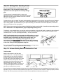
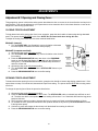
Step 29: Setting Door Opening Travel
Do not use adjustments to compensate for a poorly
balanced door. This will interfere with the proper
operation of the travel adjustments and may damage
door.
The door opener is assembled with the open travel
adjustment preset for a typical door, but all doors should be
adjusted to stop as close as possible to the door’s “natural”
fully open, resting position.
To determine the door’s “natural” fully open, resting position, disconnect door from opener using the Emergency Release
Disconnect (see page 26, HOW TO OPERATE YOUR DOOR MANUALLY) and manually raise door to its “natural” fully
open, resting position. Use this location for your open limit setting. To determine if door needs adjustment, activate the
opener to bring door to fully open position.
NOTE: If door does not open fully and opener light flashes (make sure the bulb is installed and operating) check
for an obstruction or see Adjustment #1, page 22 (Adjusting Opening Force).
To adjust for a non-standard door or to precisely set the open position: Using the wall station, operate the door and stop it
in mid-travel position; using a flathead screwdriver turn the OPEN travel adjuster for more (counter-clockwise) or less
(clockwise) travel. A 1/4 turn equals approximately 1” of trolley movement.
NOTE: Confirm that the door has stopped in the UP position as a result
of the Upper Limit Switch and not because the Trolley has hit the open
Stop Bolt, which is mounted in the Rail near the power head. The
correct condition can be verified by observing that the openers
Convenience Light does not flash
after the fully open door comes to a
stop. The faulty condition may also be confirmed visually by checking
to see if the Trolley is resting against the stop bolt.
To confirm final OPEN travel adjustment, activate the opener to bring door to
fully open position. The opener light should not
be flashing.
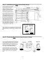
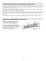
Step 30: Infrared Safety Sensor Obstruction Test
Test Procedure
Starting with the door in the fully open
position, place a 6” x 12” object on the floor
progressively one foot from the left side of
the door; center of door and one foot from
the right side of door (as illustrated). In each
position, activation of the opener with the
wall station should cause the door to move
approximately one foot, stop and then
reverse to fully open position. The same 6” x
12” object when placed on the floor should
also cause a closing door to reverse.
If the door does not respond properly to these tests, the Infrared Safety Sensors must be adjusted (refer to step 22 or 23
depending on type of sensors used). Repeat this test procedure. If the door opener still will not respond properly and fails
this test, the door may cause severe injury or death. Have a qualified service person make repairs.

20
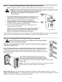
Step 31: Programming Wireless Keyless Entry (If Included)
NOTE: To facilitate installation, program the Keyless Entry station to the opener before mounting to wall.
WARNING: During programming the garage door may operate. Keep people and objects clear of the
moving door to prevent door damage or possible personal injury.
NOTE: Before programming ensure garage door is in the
“down” position.
1. Press the PROGRAM Switch button located on the garage door power
head unit once. The red PROGRAM STATUS light on the motor
power head unit and overhead lamp will turn on and remain lit for one
minute, indicating that it is ready to learn the Keyless Entry.
2. Press the desired five digit PIN (PERSONAL IDENTIFICATION
NUMBER), Example 1-2-3-4-5. The PROGRAM STATUS light will turn
on and off three times indicating a successful learn.
3. Wait five seconds and press any button on the keyless entry. The
door will move to the up position.
NOTE: If an error is made entering codes, simply press and hold
both the “7/8” and “9/0” buttons for two seconds. The Keyless
Entry will reset. Repeat programming procedure again.
A single Wireless Keyless Entry device may be programmed to operate multiple garage door openers. To program addi-
tional openers, repeat programming steps using a different five digit PIN for each additional opener
Step 32: Installing Wireless Keyless Entry (If Included)
Install all wall controls out of the reach of children and in a location where the
door can be seen before activating.
CAUTION: The keypad should be mounted a minimum of 5 feet from the floor to keep it out
of the reach of small children.
Locate a convenient place to mount the Wireless Keyless Entry. Choose a convenient location
that does not interfere with the normal opening and closing of the door. To keep keyless entry out
of the reach of children, measure and mark a spot at least five feet up from the floor. Use the
drilling template located on Page 32 to determine hole positions. Drill 5/54” pilot holes 3/4" deep at
each screw location.
Snap open the Wireless Keyless Entry case with a coin.
Secure keyless entry base into wood wall framing using the
two screws provided. Snap the front case half with the base.
Remove paper backing from instruction label and apply to a clean surface
inside garage.
NOTE: Two screws are included for mounting to wood structures. Ensure
proper hardware is used for mounting to other materials.
Battery Replacement: Under normal operating conditions, the batteries should be changed once every 12 months.
Dispose used batteries properly. To change batteries, snap open case with a coin and remove old batteries. Insert two
CR2032 or equivalent coin cell batteries and snap case together.
La page est en cours de chargement...
La page est en cours de chargement...
La page est en cours de chargement...
La page est en cours de chargement...
La page est en cours de chargement...
La page est en cours de chargement...
La page est en cours de chargement...
La page est en cours de chargement...
La page est en cours de chargement...
La page est en cours de chargement...
La page est en cours de chargement...
La page est en cours de chargement...
-
 1
1
-
 2
2
-
 3
3
-
 4
4
-
 5
5
-
 6
6
-
 7
7
-
 8
8
-
 9
9
-
 10
10
-
 11
11
-
 12
12
-
 13
13
-
 14
14
-
 15
15
-
 16
16
-
 17
17
-
 18
18
-
 19
19
-
 20
20
-
 21
21
-
 22
22
-
 23
23
-
 24
24
-
 25
25
-
 26
26
-
 27
27
-
 28
28
-
 29
29
-
 30
30
-
 31
31
-
 32
32


Quantum 3314 Owner Installation And User Manual
- Catégorie
- Porte de garage
- Taper
- Owner Installation And User Manual
dans d''autres langues
- English: Quantum 3314
Autres documents
-
Craftsman CMXEOCG772 Manuel utilisateur
-
Chamberlain C610C Mode d'emploi
-
-
-
-
-
-
-
-