Yamaha YSP-500 Le manuel du propriétaire
- Catégorie
- Microphones
- Taper
- Le manuel du propriétaire

YAMAHA ELECTRONICS CORPORATION, USA
6660 ORANGETHORPE AVE., BUENA PARK, CALIF. 90620, U.S.A.
YAMAHA CANADA MUSIC LTD.
135 MILNER AVE., SCARBOROUGH, ONTARIO M1S 3R1, CANADA
YAMAHA ELECTRONIK EUROPA G.m.b.H.
SIEMENSSTR. 22-34, 25462 RELLINGEN BEI HAMBURG, GERMANY
YAMAHA ELECTRONIQUE FRANCE S.A.
RUE AMBROISE CROIZAT BP70 CROISSY-BEAUBOURG 77312 MARNE-LA-VALLEE CEDEX02, FRANCE
YAMAHA ELECTRONICS (UK) LTD.
YAMAHA HOUSE, 200 RICKMANSWORTH ROAD WATFORD, HERTS WD18 7GQ, ENGLAND
YAMAHA SCANDINAVIA A.B.
J A WETTERGRENS GATA 1, BOX 30053, 400 43 VÄSTRA FRÖLUNDA, SWEDEN
YAMAHA MUSIC AUSTRALIA PTY, LTD.
17-33 MARKET ST., SOUTH MELBOURNE, 3205 VIC., AUSTRALIA
©
2007 All rights reserved.
Printed in Malaysia WM28800
YSP-500
YSP-500
Digital Sound Projector
TM
Système Acoustique Numérique
E
OWNER’S MANUAL
MODE D’EMPLOI
MANUALE DI ISTRUZIONI
MANUAL DE INSTRUCCIONES
YSP-500_E-cv.fm Page 1 Thursday, September 20, 2007 8:49 AM

CAUTION: READ THIS BEFORE OPERATING THIS UNIT.
i En
1
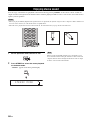
To assure the finest performance, please read this manual
carefully. Keep it in a safe place for future reference.
2 Install this sound system in a well ventilated, cool, dry, clean
place with at least 5 cm (2 in) of space above (or below) this unit
– away from direct sunlight, heat sources, vibration, dust,
moisture, and/or cold.
3 Locate this unit away from other electrical appliances, motors, or
transformers to avoid humming sounds.
4 Do not expose this unit to sudden temperature changes from cold
to hot, and do not locate this unit in an environment with high
humidity (i.e. a room with a humidifier) to prevent condensation
inside this unit, which may cause an electrical shock, fire,
damage to this unit, and/or personal injury.
5 Avoid installing this unit where foreign object may fall onto this
unit and/or this unit may be exposed to liquid dripping or
splashing. On the top of this unit, do not place:
– Other components, as they may cause damage and/or
discoloration on the surface of this unit.
– Burning objects (i.e. candles), as they may cause fire, damage
to this unit, and/or personal injury.
– Containers with liquid in them, as they may fall and liquid
may cause electrical shock to the user and/or damage to this
unit.
6 Do not cover this unit with a newspaper, tablecloth, curtain, etc.
in order not to obstruct heat radiation. If the temperature inside
this unit rises, it may cause fire, damage to this unit, and/or
personal injury.
7 Do not plug in this unit to a wall outlet until all connections are
complete.
8 Do not operate this unit upside-down. It may overheat, possibly
causing damage.
9 Do not use force on switches, knobs and/or cords.
10 When disconnecting the power supply cable from the wall outlet,
grasp the plug; do not pull the cable.
11 Do not clean this unit with chemical solvents; this might damage
the finish. Use a clean, dry cloth.
12 Only voltage specified on this unit must be used. Using this unit
with a higher voltage than specified is dangerous and may cause
fire, damage to this unit, and/or personal injury. Yamaha will not
be held responsible for any damage resulting from use of this unit
with a voltage other than specified.
13 To prevent damage by lightning, keep the power supply cable
disconnected from a wall outlet or this unit during a lightning
storm.
14 Do not attempt to modify or fix this unit. Contact qualified
Yamaha service personnel when any service is needed.
The cabinet should never be opened for any reasons.
15 When not planning to use this unit for long periods of time (i.e.
vacation), disconnect the power supply cable from the wall
outlet.
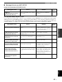
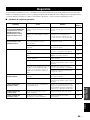
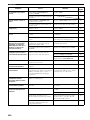
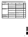
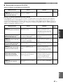
16 Be sure to read the “Troubleshooting” section on common
operating errors before concluding that this unit is faulty.
17 Before moving this unit, press STANDBY/ON to set this unit in
standby mode, and disconnect the power supply cable from the
wall outlet.
18 Condensation will form when the surrounding temperature
changes suddenly. Disconnect the power supply cable from the
outlet, then leave the unit alone.
19 When using the unit for a long time, the unit may become warm.
Turn the power off, then leave the unit alone for cooling.
20 Install this unit near the AC outlet and where the AC power plug
can be reached easily.
21 The batteries shall not be exposed to excessive heat such as
sunshine, fire or the like.
Caution: Read this before operating this unit.
WARNING
TO REDUCE THE RISK OF FIRE OR ELECTRIC SHOCK, DO
NOT EXPOSE THIS UNIT TO RAIN OR MOISTURE.
WARNING
THE POWER SUPPLY CABLE OF THIS UNIT MUST BE
CONNECTED TO THE MAIN SOCKET OUTLET VIA A
PROTECTIVE EARTHING CONNECTION.
This unit is not disconnected from the AC power source as long as
it is connected to the AC wall outlet, even if this unit itself is
turned off by STANDBY/ON. This state is called the standby
mode. In this state, this unit is designed to consume a very small
quantity of power.
FOR U.K. CUSTOMERS
If the socket outlets in the home are not suitable for the plug
supplied with this appliance, it should be cut off and an
appropriate 3 pin plug fitted. For details, refer to the instructions
described below. Note that the plug severed from the mains lead
must be destroyed, as a plug with bared flexible cord is hazardous
if engaged in a live socket outlet.
IMPORTANT
THE WIRES IN MAINS LEAD ARE COLOURED IN
ACCORDANCE WITH THE FOLLOWING CODE:
Blue: NEUTRAL
Brown: LIVE
As the colours of the wires in the mains lead of this apparatus may
not correspond with the coloured markings identifying the
terminals in your plug, proceed as follows:
The wire which is coloured BLUE must be connected to the
terminal which is marked with the letter N or coloured BLACK.
The wire which is coloured BROWN must be connected to the
terminal which is marked with the letter L or coloured RED. Make
sure that neither core is connected to the earth terminal of the three
pin plug.
CAUTION
Danger of explosion if battery is incorrectly replaced. Replace
only with the same or equivalent type.
CAUTION
Use of controls or adjustments or performance of procedures other
than those specified herein may result in hazardous radiation
exposure.
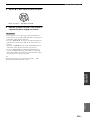
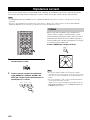
This symbol mark is according to the
EU directive 2002/96/EC.
This symbol mark means that electrical
and electronic equipment, at their end-
of-life, should be disposed of separately
from your household waste.
Please act according to your local rules
and do not dispose of your old products
with your normal household waste.

PREPARATIONINTRODUCTION
BASIC
OPERATION
ADVANCED
OPERATION
ADDITIONAL
INFORMATION
SETUP
English
1 En
Overview.................................................................. 2
Features ................................................................... 3
Using this manual ................................................... 5
Supplied accessories ............................................... 6
Controls and functions ........................................... 7
Front panel ................................................................. 7
Front panel display .................................................... 8
Rear panel .................................................................. 9
Remote control......................................................... 10
Installation............................................................. 13
Before installing this unit......................................... 13
Installing this unit .................................................... 13
Connections........................................................... 16
Before connecting components................................ 17
Connecting a TV...................................................... 18
Connecting a DVD player/recorder ......................... 19
Connecting a digital satellite tuner
or a cable TV tuner.............................................. 20
Connecting a digital airwave tuner .......................... 21
Connecting a VCR................................................... 22
Connecting other external components ................... 23
Connecting a subwoofer .......................................... 24
Connecting the AC power supply cable .................. 25
Getting started ...................................................... 26
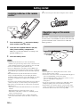
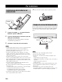
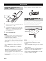
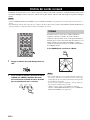
Installing batteries in the remote control ................. 26
Operation range of the remote control..................... 26
Turning on this unit or setting it to the standby mode
............................................................................. 27
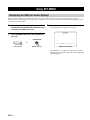
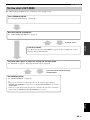
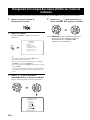
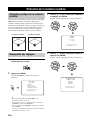
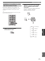
Using SET MENU................................................. 28
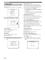
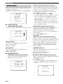
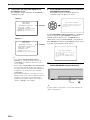
Displaying the OSD (on-screen display) ................. 28
The flow chart of SET MENU................................. 29
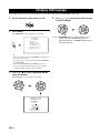
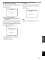
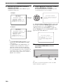
Changing OSD language...................................... 30
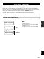
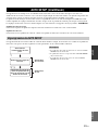
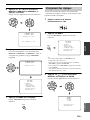
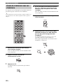
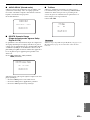
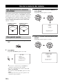
AUTO SETUP (IntelliBeam) ............................... 31
The flow chart of AUTO SETUP ............................ 31
Installing the IntelliBeam microphone .................... 32
Using AUTO SETUP (IntelliBeam)........................ 33
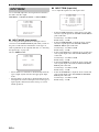
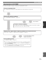
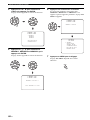
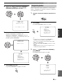
Using the system memory .................................... 38
Convenient usage of the system memory ................ 38
Saving settings......................................................... 38
Loading settings....................................................... 39
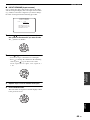
Playback ................................................................ 41
Selecting the input source........................................ 41
Playing back sources................................................ 42
Adjusting the volume............................................... 43
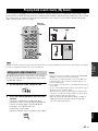
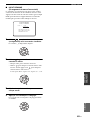
Enjoying surround sound .................................... 44
5 Beam..................................................................... 44
Stereo plus 3 Beam .................................................. 45
3 Beam..................................................................... 45
My Surround............................................................ 45
Enjoying 2-channel sources in surround sound....... 47
Enjoying TV in surround sound .............................. 48
Adjusting surround mode parameters...................... 49
Enjoying stereo sound...........................................50
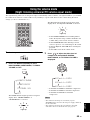
Playing back sound clearly (My Beam)...............51
Using auto-adjust function....................................... 51
Using manual-adjust function.................................. 52
Using the volume mode
(Night listening enhancer/TV volume equal
mode) ..................................................................53
Using the sleep timer.............................................54
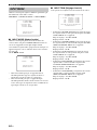
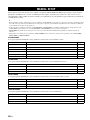
MANUAL SETUP.................................................56
Using MANUAL SETUP........................................ 57
BEAM MENU ......................................................... 58
SOUND MENU....................................................... 62
INPUT MENU......................................................... 64
DISPLAY MENU.................................................... 66
Adjusting the audio balance.................................67
Using the test tone ................................................... 67
Using the audio output being played back............... 68
Selecting the input mode.......................................70
Adjusting the system parameters ........................71
Using the system parameters ................................... 71
Setting the MEMORY PROTECT .......................... 72
Setting the MAX VOLUME.................................... 73
Setting the TURN ON VOLUME ........................... 73
Setting the DEMO MODE ...................................... 74
Setting the PANEL INP. KEY ................................ 75
Disabling the front panel keys ................................. 76
Setting the FACTORY PRESET............................. 77
Remote control features........................................79
Setting remote control codes ................................... 79
Controlling other components ................................. 80
Using the TV macro ................................................ 83
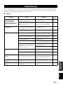
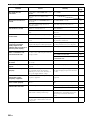
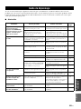
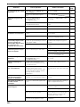
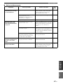
Troubleshooting.....................................................85
Glossary..................................................................88
Index.......................................................................90
Specifications .........................................................91
List of remote control codes...........................................i
Contents
INTRODUCTION
PREPARATION
SETUP
BASIC OPERATION
ADVANCED OPERATION
ADDITIONAL INFORMATION

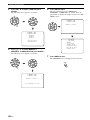
Overview
2 En
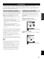
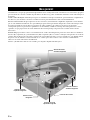
It is generally accepted that in order to fully enjoy the benefits of surround sound at home, you must endure the agony of
wiring and installing a great number of speakers in the hope that your listening room will give you the same kind of
surround sound experience as your local movie theater.
Yamaha YSP-500 Digital Sound Projector challenges this preconception that complicated speaker setup and troublesome
wiring go hand-in-hand with the enjoyment of multi-channel surround sound.
This slimline unit does away with the need for complicated wiring and installation worries, leaving you with a unit that is
not only easy to set up, but is also capable of reproducing the kind of powerful surround sound you have been waiting for
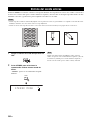
from its built-in 2 woofers and 16 full-range small speakers.
You can fine-tune the parameters of this unit to adjust the delay time for separate sound beams, resulting in highly
directional sound that comes in on the listening position from all directions.
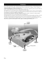
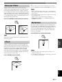
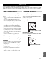
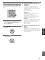
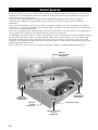
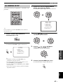
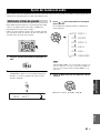
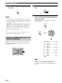
The YSP-500 projects sound beams containing surround sound information for the front right (R), front left (L), surround
right (SR), and surround left (SL) speaker positions, which are reflected off the walls of your listening room before
reaching the actual listening position. With the addition of center (C) sound beams, this Digital Sound Projector creates
true-to-life 5.1-channel surround sound that makes you feel as if there are actual speakers around the room.
Sit back and enjoy the real sound experience of this simple, yet stylish Digital Sound Projector.
Overview
SL
SR
R
L
C
Listening position
Imaginary
surround left
speaker
Imaginary
surround right
speaker
Imaginary
front left
speaker
Imaginary
front right
speaker
Imaginary
center
speaker

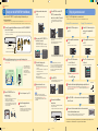
Features
3 En
INTRODUCTION
English
Digital Sound Projector™
The Digital Sound Projector technology allows one slim
unit to control and steer multiple channels of sound to
generate multi-channel surround sound, thus eliminates
the need for satellite loudspeakers and cabling normally
associated with conventional surround sound systems.
This unit also employs the beam modes that let you enjoy
the surround sound (5 Beam, Stereo plus 3 Beam, 3 Beam,
and My Surround), stereo playback, and My Beam.
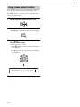
My Surround
In addition to the above mentioned beam modes, this unit
is equipped with My Surround beam mode that allows you
to enjoy surround system even in a small listening area.
My Surround is a function integrated and optimized with
DiMAGIC’s Euphony technology and Yamaha’s Beam
reproduction system.
My Beam
This unit employs My Beam that ensures a clear sound in
a noisy environment. You can adjust the beam angle
manually or automatically using the supplied remote
control to the maximum of 30°, rightward and leftward.
Versatile Remote Control
The supplied remote control comes with preset remote
control codes used to control the DVD player, VCR, cable
TV tuner, and digital satellite tuner connected to this unit.
In addition, the remote control is equipped with the macro
capability that enables a series of operations with the press
of a single button.
AUTO SETUP (IntelliBeam)
This unit employs the automatic sound beam and acoustic
optimization technology with the aid of the supplied
IntelliBeam microphone. You can avoid troublesome
listening-based speaker setup and achieve highly accurate
sound beam adjustments that best match your listening
environment.
Compatibility with the Newest Technologies
This unit employs decoders compatible with Dolby
Digital, DTS, Dolby Pro Logic, Dolby Pro Logic II, and
DTS Neo:6.
◆ Dolby Digital
This is the standard audio signal format used on various
digital media such as DVD, Blu-ray, and HD DVD. This
surround technology delivers high-quality digital audio for up
to 5.1 discrete channels to produce a directional and more
realistic effect.
◆ DTS
This is the standard audio signal format used on various
digital media such as DVD, Blu-ray, and HD DVD. This
surround technology delivers high-quality digital audio for up
to 5.1 discrete channels to produce a directional and more
realistic effect.
◆ Dolby Pro Logic
This sophisticated, matrix decoding technology up-converts
any 2-channel source audio to a 5.1-channel full bandwidth
playback, resulting in a surround sound experience.
◆ Dolby Pro Logic II
This is a redesigned version of Dolby Pro Logic that employs
2 stereo surround channels, a subwoofer, and a greatly
enhanced steering logic. This improved technology provides
an exceptionally stable sound field that simulates 5.1 to a
much greater degree than the original Dolby Pro Logic.
◆ DTS Neo:6
This technology decodes the conventional 2-channel sources
for 6-channel playback, enabling playback with the full-range
channels with higher separation. Music mode and Cinema
mode are available to play back music and movie sources
respectively.
Features
01EN_YSP-500_G.book Page 3 Monday, January 14, 2008 10:01 AM
Black process 45.0° 240.0 LPI

Features
4 En
The “ ” logo and “IntelliBeam” are trademarks of
YAMAHA Corporation.
Manufactured under license from Dolby Laboratories.
“Dolby”, “Pro Logic”, and the double-D symbol are trademarks
of Dolby Laboratories.
“DTS” and “Neo:6” are registered trademarks of DTS, Inc.
Manufactured under license from 1 Ltd. Worldwide patents
applied for.
The “ ” logo and “Digital Sound Projector
™
” are trademarks
of 1 Ltd.
TruBass, SRS and the “ ” symbol are registered trademarks
of SRS Labs, Inc. TruBass technology is incorporated under
license from SRS Labs, Inc.
™
is a trademark of DiMAGIC Co., Ltd.

Using this manual
5 En
INTRODUCTION
English
• This manual describes how to connect and operate this unit. For details regarding the operation of external components, refer to the
supplied owner’s manual for each component.
• Operations in this manual use keys on the supplied remote control of this unit unless otherwise specified.
• y indicates a tip for your operation.
• This manual is printed prior to production. Designs and specifications are subject to change in part as a result of improvements, etc. In
case of differences between the manual and the product, the product has priority.
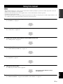
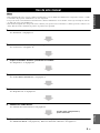
1 Install this unit in your listening room.
See “Installation” on page 13.
2 Connect this unit to your TV and other external components.
See “Connections” on page 16.
3 Prepare the remote control and turn on the power of this unit.
See “Getting started” on page 26.
4 Run AUTO SETUP.
See “AUTO SETUP (IntelliBeam)” on page 31.
5 Play back a source.
See “Playback” on page 41.
6 Change the beam modes.
See “Enjoying surround sound” on page 44.
7 Run MANUAL SETUP to fine-tune settings and/or set remote control codes.
See “MANUAL SETUP” on page 56 and “Remote control features” on page 79.
Using this manual
Notes
If you want to make additional settings
and adjustments

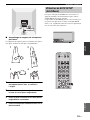
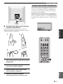
Supplied accessories
6 En
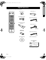
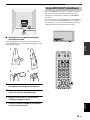
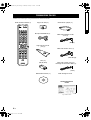
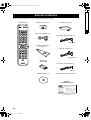
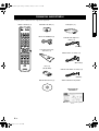
Check that you have received all of the following parts.
Supplied accessories
STEREO MY SUR.
MY BEAM
SLEEP
INPUTMODE
CH LEVEL MENU
RETURNTEST
TV VOL
VOLUME
MUTE
TV INPUT TV MUTE
ENTER
SUR. DECODE
CODE SET
5BEAM ST+3BEAM 3BEAM
VOL MODE
AUTO
SETUP
MACRO
TV
INPUT2INPUT1
YSP
TV/AV
CH
4
6
321
VCR DVD
TV
STB AUX
TV
POWERPOWERSTANDBY/ON
+10
0
78
9
5
AV
Remote control (×1)
Batteries (×2)
(AA, R6, UM-3)
OSD* video pin cable (×1)
IntelliBeam microphone
(×1)
Audio pin cable (×1)
Digital audio pin cable (×1)
Optical cable (×1)Cable clamp (×1)
Cardboard microphone
stand (×1)
(Orange)
(White/Red)
(Yellow)
Demonstration DVD
(×1)
QUICK REFERENCE
GUIDE
* The number of provided languages
varies depending on the model.
*OSD: On-Screen Display
01EN_YSP-500_G.book Page 6 Monday, January 14, 2008 10:01 AM
Black process 45.0° 240.0 LPI

Controls and functions
7 En
INTRODUCTION
English
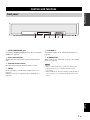
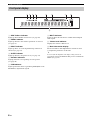
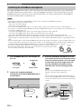
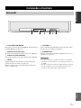
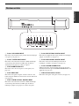
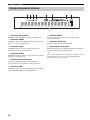
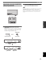
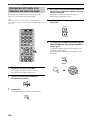
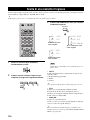
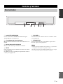
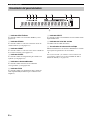
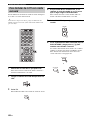
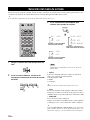
1 INTELLIBEAM MIC jack
Connect the supplied IntelliBeam microphone for AUTO
SETUP (see page 32).
2 Front panel display
Shows information about the operational status of this
unit.
3 Remote control sensor
Receives infrared signals from the remote control.
4 INPUT
Press repeatedly to switch between input sources (see
page 41).
Outputs a test tone to experience the sound beam (see
page 74).
5 VOLUME +/–
Controls the volume level of all audio channels (see
page 43).
6 STANDBY/ON
Turns on the power of this unit or sets it to the standby
mode (see page 27).
• When you turn on this unit, you will hear a click sound
followed by the 4 to 5-second interval before sound
reproducing.
• In the standby mode, this unit consumes a small amount of
power in order to receive infrared signals from the remote
control.
Controls and functions
Front panel
INTELLIBEAM MIC INPUT VOLUME STANDBY/ON
142653
Notes

Controls and functions
8 En
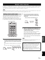
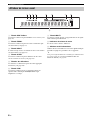
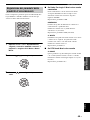
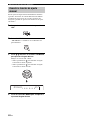
1 SRS TruBass indicator
Lights up when TruBass is turned on (see page 63).
2 EQUAL indicator
Lights up when the TV volume equal mode is selected
(see page 53).
3 NIGHT indicator
Lights up when one of the night listening enhancers is
selected (see page 53).
4 SLEEP indicator
Lights up when the sleep timer is set (see page 54).
5 Decoder indicators
Light up when the corresponding decoder operates
(see page 46).
6 PCM indicator
Lights up when this unit is reproducing PCM (Pulse Code
Modulation) digital audio signals.
7 MULTI indicator
Lights up when this unit detects a multi channel digital
audio signal.
8 Volume level indicator
Displays the current volume level.
9 Multi-information display
Shows information with alphanumeric characters when
you adjust the parameters of this unit.
y
You can adjust the brightness and display setting of the front
panel display using the F.DISPLAY SET parameter in MANUAL
SETUP (see page 66).
Front panel display
1 2 3 4
6 7
8
9
5

Controls and functions
9 En
INTRODUCTION
English
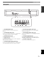
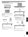
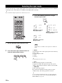
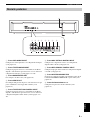
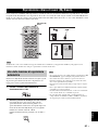
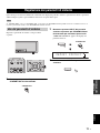
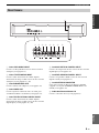
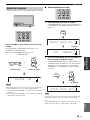
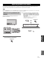
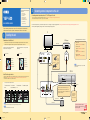
1 VCR AUDIO INPUT jacks
Connect your VCR via an analog connection (see
page 19).
2 TV/STB AUDIO INPUT jacks
Connect your TV, digital satellite tuner, or cable TV tuner
via an analog connection (see pages 18 and 20).
3 SUBWOOFER OUT jack
Connect your subwoofer (see page 24).
4 VIDEO OUT jack
Connect to the video input jack of your TV to display the
OSD of this unit (see page 18).
5 TV/STB OPTICAL DIGITAL INPUT jack
Connect your TV, digital satellite tuner, or cable TV tuner
via an optical digital connection (see pages 18 and 20).
6 AUX OPTICAL DIGITAL INPUT jack
Connect an external component via an optical digital
connection (see page 23).
7 DVD COAXIAL DIGITAL INPUT jack
Connect your DVD player via a coaxial digital connection
(see page 19).
8 SYSTEM CONNECTOR jack
Use to connect a Yamaha subwoofer equipped with a
SYSTEM CONNECTOR jack to this unit (see page 24).
9 AC power supply cable
Connect to the AC wall outlet (see page 25).
Rear panel
R
L
VCR TV/STB VIDEO TV/STB AUX
OPTICAL COAXIAL
DIGITAL INPUTOUTAUDIO INPUT
DVD SYSTEM
CONNECTOR
SUBWOOFER
12 34 56 7 8
9
R
L
VCR TV/STB VIDEO TV/STB AUX
OPTICAL COAXIAL
DIGITAL INPUTOUTAUDIO INPUT
DVD SYSTEM
CONNECTOR
SUBWOOFER

Controls and functions
10 En
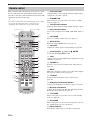
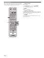
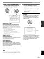
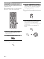
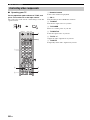
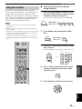
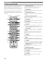
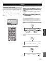
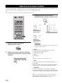
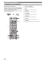
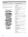
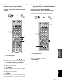
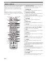
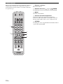
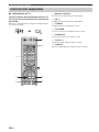
This section describes the functions of the remote control
used to control this unit. Some buttons marked with an
asterisk (*) share the common functions between the YSP
and TV/AV operation modes (N).
y
You can also control other components using the remote control
once you set the appropriate remote control codes. See
“Controlling other components” on page 80 for details.
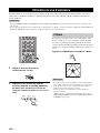
1 Infrared window
Outputs infrared control signals. Aim this window at the
component you want to operate.
2 STANDBY/ON
Turns on the power of this unit or sets it to the standby
mode (see page 27).
3 Transmission indicator
Lights up when infrared control signals are being output.
4 Input selector buttons
Use to select an input source (STB, VCR, DVD, AUX, or
TV).
5 VOL MODE
Turns on or off the volume modes (see page 53).
6 AUTO SETUP
Enters the AUTO SETUP menu (see page 31).
7 CH LEVEL
Adjusts the volume level of each channel (see page 68).
8 Cursor buttons / / / , ENTER
Select and adjust SET MENU items.
9 TEST
Outputs a test tone when adjusting the output level of each
channel (see page 67).
0 VOLUME +/–
Increases or decreases the volume level of this unit (see
page 43).
A MUTE
Mutes the sound. Press again to restore the audio output to
the previous volume level (see page 43).
B TV INPUT
Toggles between the input sources on the TV (see
page 80).
C DVD player/VCR control buttons
Control your DVD player or VCR (see pages 81 and 82).
D My Beam microphone
Collects the test tones from this unit when using the My
Beam auto-adjust function (see page 51).
E TV POWER
Turns on the power of your TV or sets it to the standby
mode (see page 80).
F AV POWER
Turns on the power of the selected component or sets it to
the standby mode (see pages 81 and 82).
G INPUT1/INPUT2
Switches the input source on your TV (see page 80).
Remote control
4
6
321
+10
0
78
9
5
STEREO
MY BEAM
SLEEP
INPUTMODE
CH LEVEL MENU
RETURNTEST
TV VOL
VOLUME
MUTE
TV INPUT TV MUTE
CODE SET
5BEAM ST+3BEAM 3BEAM
VOL MODE
AUTO
SETUP
MACRO
TV
INPUT2INPUT1
YSP
TV/AV
CH
STB
TV
VCR DVD AUX
TVAV
POWERPOWERSTANDBY/ON
ENTER
SUR. DECODE
MY SUR.
1D
E
F
G
I
H
J
K
L
M
N
O
P
Q
R
2
3
4
5
6
7
9
8
0
A
B
C
*
*
*
*
*
*
*
*

Controls and functions
11 En
INTRODUCTION
English
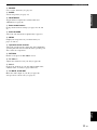
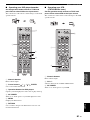
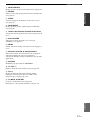
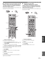
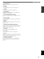
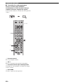
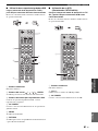
H MACRO
Use to set the TV macro (see page 83).
I SLEEP
Sets the sleep timer (see page 54).
J INPUTMODE
Toggles between input modes (AUTO, DTS, and
ANALOG) (see page 70).
K Beam mode buttons
Change the beam mode settings (see pages 44, 50, and
51).
L SUR. DECODE
Selects the surround mode for playback (see page 47).
M MENU
Displays the setup menu on your TV monitor (see
pages 33 and 57).
N Operation mode selector
Selects the operation mode of this unit. Select YSP when
operating this unit and select TV/AV when operating your
TV or other AV components.
O RETURN
Returns to the previous SET MENU screen.
P TV VOL +/–
Adjusts the volume level of your TV (see page 80).
Q CH +/–
Changes the channels of your TV, digital satellite tuner,
cable TV tuner, or VCR (see pages 80 and 82).
R TV MUTE, CODE SET
Mutes the audio output of your TV (see page 80).
Sets up remote control codes (see page 79).

Controls and functions
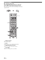
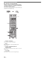
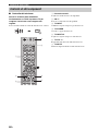
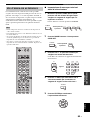
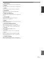
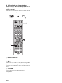
12 En
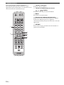
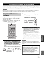
This section describes the functions of the remote control
used to control other components when the TV/AV mode
is selected with the operation mode selector (4).
1 Numeric buttons
Enter numbers.
2 Cursor buttons / / / , ENTER
Use to select DVD menu items.
3 MENU
Displays the DVD menu.
4 Operation mode selector
Selects the operation mode of this unit. Select YSP when
operating this unit and select TV/AV when operating your
TV or other AV components.
5 RETURN
Use to return to the previous DVD menu screen or exit
from the DVD menu.
4
6
321
+10
0
78
9
5
STEREO
MY BEAM
SLEEP
INPUTMODE
CH LEVEL MENU
RETURNTEST
TV VOL
VOLUME
MUTE
TV INPUT TV MUTE
CODE SET
5BEAM ST+3BEAM 3BEAM
VOL MODE
AUTO
SETUP
MACRO
TV
INPUT2INPUT1
YSP
TV/AV
CH
STB
TV
VCR DVD AUX
TVAV
POWERPOWERSTANDBY/ON
ENTER
SUR. DECODE
MY SUR.
1
2
3
5
4

Installation
13 En
PREPARATION
English
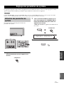
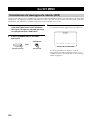
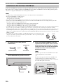
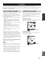
This section describes a suitable installation location to install this unit using a rack.
Depending on your installation environment, connections with external components can be done before installing this
unit. We recommend that you temporarily place and arrange all components, including this unit, in order to decide which
procedure should come first.
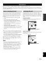
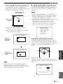
This unit creates surround sound by reflecting projected
sound beams off the walls of your listening room. The
surround sound effects produced by this unit may not be
sufficient when this unit is installed in the following
locations.
• Rooms with walls inadequate for reflecting sound
beams
• Rooms with acoustically absorbent walls
• Rooms with measurements outside the following
range: W (3 to 7 m (10 to 23 ft)) x H (2 to 3.5 m (7 to
11.5 ft)) x D (3 to 7 m (10 to 23 ft))
• Rooms with less than 1.8 m (6 ft) from the listening
position to this unit
• Rooms where objects such as furniture are likely to
obstruct the path of sound beams
• Rooms where the listening position is close to the walls
• Rooms where the listening position is not in front of
this unit
y
• You can enjoy surround sound by selecting My Surround (see
page 45) as the beam mode even if your listening room may not
fulfill the above conditions (except when the listening position
is not directly facing toward the front of this unit).
• You can also enjoy surround sound by selecting stereo playback
(see page 50) or My Beam (see page 51) as the beam mode even
if your listening room may not fulfill the above conditions.
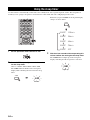
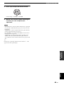
Make sure you leave an adequate amount of ventilation
space so that heat can escape. Make at least 5 cm (2 in) of
space above this unit.
• We do not recommend putting this unit directly on the floor of
your listening room. Please install this unit using a rack.
• This unit weights 8.5 kg (18 lbs 12 oz). Be sure to install this
unit where it will not fall subject to vibrations, such as from an
earthquake, and where it is out of the reach of children.
• When using a cathode-ray tube (CRT) TV, do not install this
unit directly above your TV.
• This unit is shielded against magnetic rays. However, if the
picture on your TV screen becomes blurred or distorted, we
recommend moving this unit away from your TV.
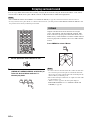
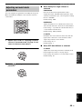
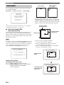
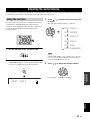
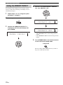
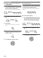
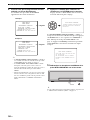
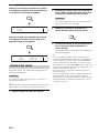
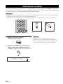
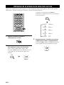
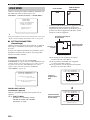
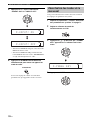
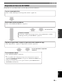
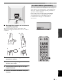
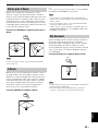
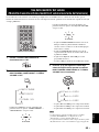
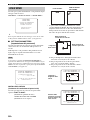
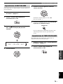
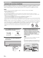
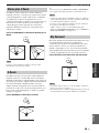
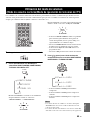
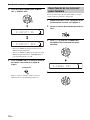
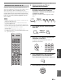
Install this unit where there are no obstacles such as
furniture obstructing the path of sound beams. Otherwise,
the desired surround sound effects may not be achieved.
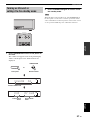
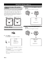
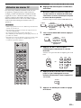
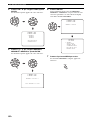
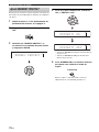
You may install this unit in parallel with the wall or in the
corner.
Parallel installation
Install this unit in the exact center of the wall when it is
measured from the left and right corners.
Corner installation
Install this unit in the corner at a 40º to 50º angle from the
adjacent walls.
Installation
Before installing this unit
Notes
Installing this unit
An object, such as furniture
40° to 50°
An object, such as furniture

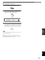
14 En
Installation
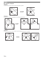
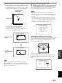
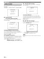
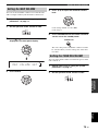
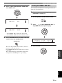
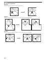
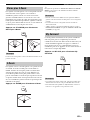
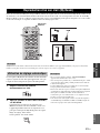
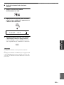
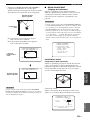
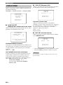
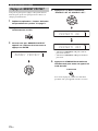
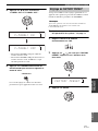
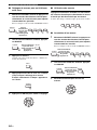
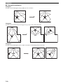
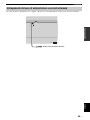
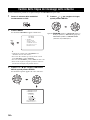
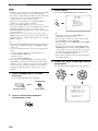
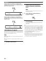
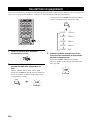
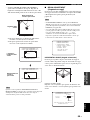
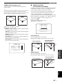
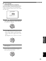
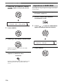
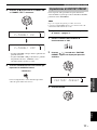
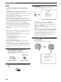
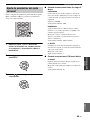
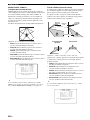
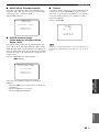
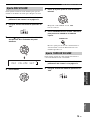
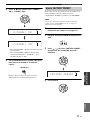
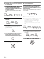
■ Installation examples
Example 1
Install this unit as close to the exact center of the wall as possible.
Example 2
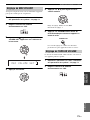
Install this unit so that the sound beams can be reflected off the walls.
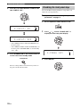
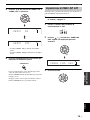
Example 3
Install this unit as close to the exact front of your normal listening position as possible.

15 En
Installation
PREPARATION
English
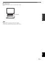
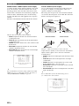
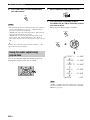
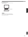
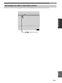
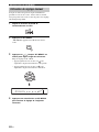
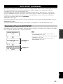
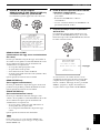
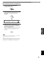
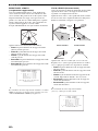
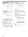
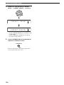
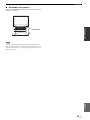
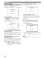
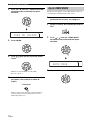
■ Using a rack
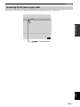
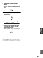
Install this unit under your TV in a commercially available
rack.
Make sure that the rack is large enough to allow adequate
ventilation space around this unit (see page 13) and that it is
strong enough to support the weight of both this unit and your TV.
Note
This unit

Connections
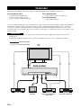
16 En
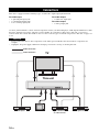
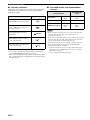
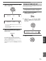
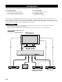
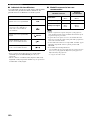
This unit is equipped with the following types of audio/video input/output jacks/terminal:
For audio input
• 2 optical digital input jacks
• 1 coaxial digital input jacks
• 2 sets of analog input jacks
For audio output
• 1 subwoofer output jack
For video output
• 1 analog output jack
Use these jacks/terminal to connect external components such as your TV, DVD player, VCR, digital satellite tuner, cable
TV tuner, digital air wave tuner, and game console. Further, by connecting a subwoofer to this unit, you can enjoy
reinforced low-bass sounds. For details on how to connect various types of external components to this unit, see pages 18
to 24.
• Do not connect this unit or other components to the mains power until all connections between components are
complete.
• Unplug the AC power supply cable before changing connections, moving or cleaning this unit.
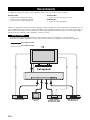
Connections
CAUTION
TV
This unit
Audio connection
Video connection
VCR or game consoleDVD player Subwoofer Digital satellite tuner
or cable TV tuner

17 En
Connections
PREPARATION
English
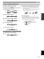
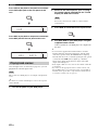
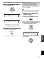
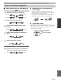
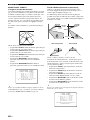
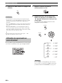
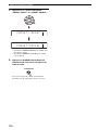
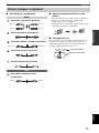
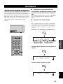
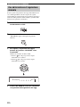
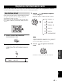
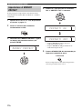
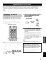
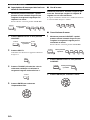
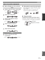
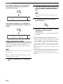
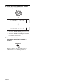
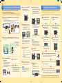
■ Cables used for connections
Audio pin cable (supplied)
Optical cable (supplied)
Digital audio pin cable (supplied)
Subwoofer pin cable
System connector cable
OSD video pin cable (supplied)
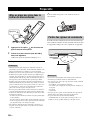
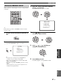
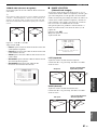
■ Notes on connecting the optical cable
• Pull out the cap before connecting the optical cable.
When you are not using the optical cable, be sure to put
the cap back in place.
• When inserting the cable into the optical digital jack,
make sure the direction is correct.
■ Affixing cables
To prevent cables from becoming unplugged, place the
supplied cable clamp with the open side facing upward,
attach it to the rear panel of this unit in a suitable position,
and then affix cables in the cable clamp.
Before connecting components
Audio
Video
(White)
(Red)
(White)
(Red)
(Orange)(Orange)
5
(Yellow)(Yellow)
Cap
Optical cable
Attach to this unit

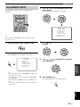
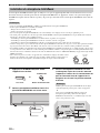
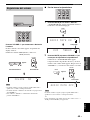
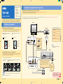
18 En
Connections
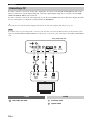
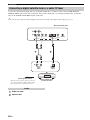
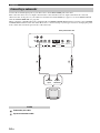
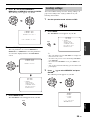
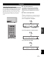
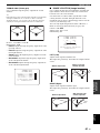
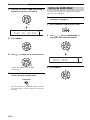
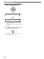
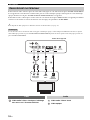
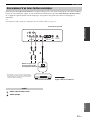
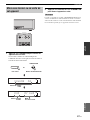
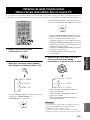
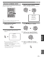
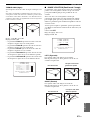
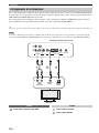
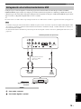
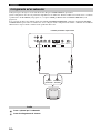
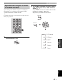
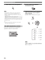
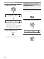
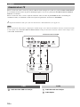
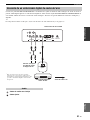
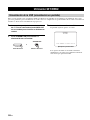
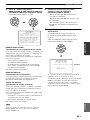
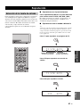
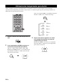
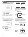
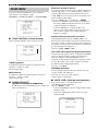
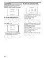
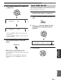
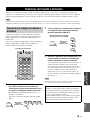
For audio connection, connect the analog audio output jacks on your TV to the TV/STB AUDIO INPUT jacks on this
unit. If your TV has an optical digital output jack, connect the optical digital output jack on your TV to the TV/STB
OPTICAL DIGITAL INPUT jack on this unit.
For video connection, connect the video input jack on your TV to the VIDEO OUT jack on this unit to display the OSD
for easy viewing when you adjust the system parameters in SET MENU.
y
To prevent the optical cable from being unplugged, affix the optical cable in the supplied cable clamp (see page 17).
If you make analog and optical digital audio connections at the same time as shown in the illustration below, the digital audio signals
input at the TV/STB OPTICAL DIGITAL INPUT jack take priority over the analog audio signals input at the TV/STB AUDIO INPUT
jacks.
OSD video pin cable Audio pin cable
Optical cable
Connecting a TV
Note
R
L
VCR TV/STB VIDEO TV/STB AUX
OPTICAL COAXIAL
DIGITAL INPUTOUTAUDIO INPUT
DVD SYSTEM
CONNECTOR
SUBWOOFER
Rear panel of this unit
TV
Optical
digital
output
RL
Video
input
Analog
audio
output
Video Audio
La page charge ...
La page charge ...
La page charge ...
La page charge ...
La page charge ...
La page charge ...
La page charge ...
La page charge ...
La page charge ...
La page charge ...
La page charge ...
La page charge ...
La page charge ...
La page charge ...
La page charge ...
La page charge ...
La page charge ...
La page charge ...
La page charge ...
La page charge ...
La page charge ...
La page charge ...
La page charge ...
La page charge ...
La page charge ...
La page charge ...
La page charge ...
La page charge ...
La page charge ...
La page charge ...
La page charge ...
La page charge ...
La page charge ...
La page charge ...
La page charge ...
La page charge ...
La page charge ...
La page charge ...
La page charge ...
La page charge ...
La page charge ...
La page charge ...
La page charge ...
La page charge ...
La page charge ...
La page charge ...
La page charge ...
La page charge ...
La page charge ...
La page charge ...
La page charge ...
La page charge ...
La page charge ...
La page charge ...
La page charge ...
La page charge ...
La page charge ...
La page charge ...
La page charge ...
La page charge ...
La page charge ...
La page charge ...
La page charge ...
La page charge ...
La page charge ...
La page charge ...
La page charge ...
La page charge ...
La page charge ...
La page charge ...
La page charge ...
La page charge ...
La page charge ...
La page charge ...
La page charge ...
La page charge ...
La page charge ...
La page charge ...
La page charge ...
La page charge ...
La page charge ...
La page charge ...
La page charge ...
La page charge ...
La page charge ...
La page charge ...
La page charge ...
La page charge ...
La page charge ...
La page charge ...
La page charge ...
La page charge ...
La page charge ...
La page charge ...
La page charge ...
La page charge ...
La page charge ...
La page charge ...
La page charge ...
La page charge ...
La page charge ...
La page charge ...
La page charge ...
La page charge ...
La page charge ...
La page charge ...
La page charge ...
La page charge ...
La page charge ...
La page charge ...
La page charge ...
La page charge ...
La page charge ...
La page charge ...
La page charge ...
La page charge ...
La page charge ...
La page charge ...
La page charge ...
La page charge ...
La page charge ...
La page charge ...
La page charge ...
La page charge ...
La page charge ...
La page charge ...
La page charge ...
La page charge ...
La page charge ...
La page charge ...
La page charge ...
La page charge ...
La page charge ...
La page charge ...
La page charge ...
La page charge ...
La page charge ...
La page charge ...
La page charge ...
La page charge ...
La page charge ...
La page charge ...
La page charge ...
La page charge ...
La page charge ...
La page charge ...
La page charge ...
La page charge ...
La page charge ...
La page charge ...
La page charge ...
La page charge ...
La page charge ...
La page charge ...
La page charge ...
La page charge ...
La page charge ...
La page charge ...
La page charge ...
La page charge ...
La page charge ...
La page charge ...
La page charge ...
La page charge ...
La page charge ...
La page charge ...
La page charge ...
La page charge ...
La page charge ...
La page charge ...
La page charge ...
La page charge ...
La page charge ...
La page charge ...
La page charge ...
La page charge ...
La page charge ...
La page charge ...
La page charge ...
La page charge ...
La page charge ...
La page charge ...
La page charge ...
La page charge ...
La page charge ...
La page charge ...
La page charge ...
La page charge ...
La page charge ...
La page charge ...
La page charge ...
La page charge ...
La page charge ...
La page charge ...
La page charge ...
La page charge ...
La page charge ...
La page charge ...
La page charge ...
La page charge ...
La page charge ...
La page charge ...
La page charge ...
La page charge ...
La page charge ...
La page charge ...
La page charge ...
La page charge ...
La page charge ...
La page charge ...
La page charge ...
La page charge ...
La page charge ...
La page charge ...
La page charge ...
La page charge ...
La page charge ...
La page charge ...
La page charge ...
La page charge ...
La page charge ...
La page charge ...
La page charge ...
La page charge ...
La page charge ...
La page charge ...
La page charge ...
La page charge ...
La page charge ...
La page charge ...
La page charge ...
La page charge ...
La page charge ...
La page charge ...
La page charge ...
La page charge ...
La page charge ...
La page charge ...
La page charge ...
La page charge ...
La page charge ...
La page charge ...
La page charge ...
La page charge ...
La page charge ...
La page charge ...
La page charge ...
La page charge ...
La page charge ...
La page charge ...
La page charge ...
La page charge ...
La page charge ...
La page charge ...
La page charge ...
La page charge ...
La page charge ...
La page charge ...
La page charge ...
La page charge ...
La page charge ...
La page charge ...
La page charge ...
La page charge ...
La page charge ...
La page charge ...
La page charge ...
La page charge ...
La page charge ...
La page charge ...
La page charge ...
La page charge ...
La page charge ...
La page charge ...
La page charge ...
La page charge ...
La page charge ...
La page charge ...
La page charge ...
La page charge ...
La page charge ...
La page charge ...
La page charge ...
La page charge ...
La page charge ...
La page charge ...
La page charge ...
La page charge ...
La page charge ...
La page charge ...
La page charge ...
La page charge ...
La page charge ...
La page charge ...
La page charge ...
La page charge ...
La page charge ...
La page charge ...
La page charge ...
La page charge ...
La page charge ...
La page charge ...
La page charge ...
La page charge ...
La page charge ...
La page charge ...
La page charge ...
La page charge ...
La page charge ...
La page charge ...
La page charge ...
La page charge ...
La page charge ...
La page charge ...
La page charge ...
La page charge ...
La page charge ...
La page charge ...
La page charge ...
La page charge ...
La page charge ...
La page charge ...
La page charge ...
La page charge ...
La page charge ...
La page charge ...
La page charge ...
La page charge ...
La page charge ...
La page charge ...
La page charge ...
La page charge ...
La page charge ...
La page charge ...
La page charge ...
La page charge ...
La page charge ...
La page charge ...
La page charge ...
La page charge ...
La page charge ...
La page charge ...
La page charge ...
La page charge ...
La page charge ...
La page charge ...
La page charge ...
La page charge ...
La page charge ...
La page charge ...
La page charge ...
La page charge ...
La page charge ...
La page charge ...
La page charge ...
La page charge ...
La page charge ...
La page charge ...
La page charge ...
La page charge ...
La page charge ...
La page charge ...
La page charge ...
La page charge ...
-
 1
1
-
 2
2
-
 3
3
-
 4
4
-
 5
5
-
 6
6
-
 7
7
-
 8
8
-
 9
9
-
 10
10
-
 11
11
-
 12
12
-
 13
13
-
 14
14
-
 15
15
-
 16
16
-
 17
17
-
 18
18
-
 19
19
-
 20
20
-
 21
21
-
 22
22
-
 23
23
-
 24
24
-
 25
25
-
 26
26
-
 27
27
-
 28
28
-
 29
29
-
 30
30
-
 31
31
-
 32
32
-
 33
33
-
 34
34
-
 35
35
-
 36
36
-
 37
37
-
 38
38
-
 39
39
-
 40
40
-
 41
41
-
 42
42
-
 43
43
-
 44
44
-
 45
45
-
 46
46
-
 47
47
-
 48
48
-
 49
49
-
 50
50
-
 51
51
-
 52
52
-
 53
53
-
 54
54
-
 55
55
-
 56
56
-
 57
57
-
 58
58
-
 59
59
-
 60
60
-
 61
61
-
 62
62
-
 63
63
-
 64
64
-
 65
65
-
 66
66
-
 67
67
-
 68
68
-
 69
69
-
 70
70
-
 71
71
-
 72
72
-
 73
73
-
 74
74
-
 75
75
-
 76
76
-
 77
77
-
 78
78
-
 79
79
-
 80
80
-
 81
81
-
 82
82
-
 83
83
-
 84
84
-
 85
85
-
 86
86
-
 87
87
-
 88
88
-
 89
89
-
 90
90
-
 91
91
-
 92
92
-
 93
93
-
 94
94
-
 95
95
-
 96
96
-
 97
97
-
 98
98
-
 99
99
-
 100
100
-
 101
101
-
 102
102
-
 103
103
-
 104
104
-
 105
105
-
 106
106
-
 107
107
-
 108
108
-
 109
109
-
 110
110
-
 111
111
-
 112
112
-
 113
113
-
 114
114
-
 115
115
-
 116
116
-
 117
117
-
 118
118
-
 119
119
-
 120
120
-
 121
121
-
 122
122
-
 123
123
-
 124
124
-
 125
125
-
 126
126
-
 127
127
-
 128
128
-
 129
129
-
 130
130
-
 131
131
-
 132
132
-
 133
133
-
 134
134
-
 135
135
-
 136
136
-
 137
137
-
 138
138
-
 139
139
-
 140
140
-
 141
141
-
 142
142
-
 143
143
-
 144
144
-
 145
145
-
 146
146
-
 147
147
-
 148
148
-
 149
149
-
 150
150
-
 151
151
-
 152
152
-
 153
153
-
 154
154
-
 155
155
-
 156
156
-
 157
157
-
 158
158
-
 159
159
-
 160
160
-
 161
161
-
 162
162
-
 163
163
-
 164
164
-
 165
165
-
 166
166
-
 167
167
-
 168
168
-
 169
169
-
 170
170
-
 171
171
-
 172
172
-
 173
173
-
 174
174
-
 175
175
-
 176
176
-
 177
177
-
 178
178
-
 179
179
-
 180
180
-
 181
181
-
 182
182
-
 183
183
-
 184
184
-
 185
185
-
 186
186
-
 187
187
-
 188
188
-
 189
189
-
 190
190
-
 191
191
-
 192
192
-
 193
193
-
 194
194
-
 195
195
-
 196
196
-
 197
197
-
 198
198
-
 199
199
-
 200
200
-
 201
201
-
 202
202
-
 203
203
-
 204
204
-
 205
205
-
 206
206
-
 207
207
-
 208
208
-
 209
209
-
 210
210
-
 211
211
-
 212
212
-
 213
213
-
 214
214
-
 215
215
-
 216
216
-
 217
217
-
 218
218
-
 219
219
-
 220
220
-
 221
221
-
 222
222
-
 223
223
-
 224
224
-
 225
225
-
 226
226
-
 227
227
-
 228
228
-
 229
229
-
 230
230
-
 231
231
-
 232
232
-
 233
233
-
 234
234
-
 235
235
-
 236
236
-
 237
237
-
 238
238
-
 239
239
-
 240
240
-
 241
241
-
 242
242
-
 243
243
-
 244
244
-
 245
245
-
 246
246
-
 247
247
-
 248
248
-
 249
249
-
 250
250
-
 251
251
-
 252
252
-
 253
253
-
 254
254
-
 255
255
-
 256
256
-
 257
257
-
 258
258
-
 259
259
-
 260
260
-
 261
261
-
 262
262
-
 263
263
-
 264
264
-
 265
265
-
 266
266
-
 267
267
-
 268
268
-
 269
269
-
 270
270
-
 271
271
-
 272
272
-
 273
273
-
 274
274
-
 275
275
-
 276
276
-
 277
277
-
 278
278
-
 279
279
-
 280
280
-
 281
281
-
 282
282
-
 283
283
-
 284
284
-
 285
285
-
 286
286
-
 287
287
-
 288
288
-
 289
289
-
 290
290
-
 291
291
-
 292
292
-
 293
293
-
 294
294
-
 295
295
-
 296
296
-
 297
297
-
 298
298
-
 299
299
-
 300
300
-
 301
301
-
 302
302
-
 303
303
-
 304
304
-
 305
305
-
 306
306
-
 307
307
-
 308
308
-
 309
309
-
 310
310
-
 311
311
-
 312
312
-
 313
313
-
 314
314
-
 315
315
-
 316
316
-
 317
317
-
 318
318
-
 319
319
-
 320
320
-
 321
321
-
 322
322
-
 323
323
-
 324
324
-
 325
325
-
 326
326
-
 327
327
-
 328
328
-
 329
329
-
 330
330
-
 331
331
-
 332
332
-
 333
333
-
 334
334
-
 335
335
-
 336
336
-
 337
337
-
 338
338
-
 339
339
-
 340
340
-
 341
341
-
 342
342
-
 343
343
-
 344
344
-
 345
345
-
 346
346
-
 347
347
-
 348
348
-
 349
349
-
 350
350
-
 351
351
-
 352
352
-
 353
353
-
 354
354
-
 355
355
-
 356
356
-
 357
357
-
 358
358
-
 359
359
-
 360
360
-
 361
361
-
 362
362
-
 363
363
-
 364
364
-
 365
365
-
 366
366
-
 367
367
-
 368
368
-
 369
369
-
 370
370
-
 371
371
-
 372
372
-
 373
373
-
 374
374
-
 375
375
-
 376
376
-
 377
377
-
 378
378
-
 379
379
-
 380
380
-
 381
381
-
 382
382
-
 383
383
-
 384
384


Yamaha YSP-500 Le manuel du propriétaire
- Catégorie
- Microphones
- Taper
- Le manuel du propriétaire
dans d''autres langues
- italiano: Yamaha YSP-500 Manuale del proprietario
- English: Yamaha YSP-500 Owner's manual
- español: Yamaha YSP-500 El manual del propietario
- suomi: Yamaha YSP-500 Omistajan opas
- română: Yamaha YSP-500 Manualul proprietarului
Documents connexes
-
Yamaha YSP-600 Le manuel du propriétaire
-
Yamaha YSP-1100 Le manuel du propriétaire
-
Yamaha YSP-500 Le manuel du propriétaire
-
-
-
Yamaha YSP-900 Le manuel du propriétaire
-
-
-
