Industrial Shields IS.MDUINO.21+ Mode d'emploi
- Taper
- Mode d'emploi

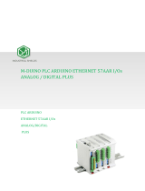
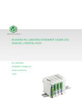
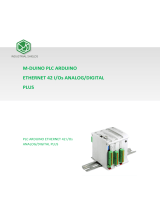
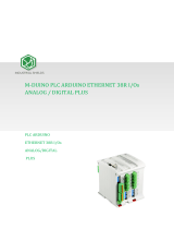
M-DUINO PLC ARDUINO
ETHERNET 21 I/Os ANALOG/DIGITAL
PLUS
PLC ARDUINO ETHERNET 21 I/Os
ANALOG/DIGITAL PLUS


Ref. IS.MDUINO.21+ Rev. 1: 21-02-2020
3
Preface
This User Guide is been implemented by Boot & Work, S.L. working
under the name Industrial Shields.
Purpose of the manual
The information contained in this manual can be used as a reference to operating, to
functions, and to the technical data of the signal modules, power supply modules and
interface modules.
Intended Audience
This User Guide is intended for the following audience:
Persons in charge of introducing automation devices.
Persons who design automation systems.
Persons who install or connect automation devices.
Persons who manage working automation installation.
Warnings:
Unused pins should not be connected. Ignoring the directive may damage the
controller.
Improper use of this product may severely damage the controller.
Refer to the controller’s User Guide regarding wiring considerations.
Before using this product, it is the responsibility of the user to read the product’s User
Guide and all accompanying documentation.
Maintenance must be performed by qualified personnel familiarized with the
construction, operation, and hazards involved with the control.
Maintenance should be performed with the control out of operation and
disconnected from all sources of power.
Care should be taken when servicing electrostatic sensitive components. The
manufacturer's recommendations for these components should be followed.
The M-Duino Family PLCs are Open Type Controllers. It is required that you install the
M-Duino PLC in a housing, cabinet, or electric control room. Entry to the housing,

Ref. IS.MDUINO.21+ Rev. 1: 21-02-2020
4
cabinet, or electric control room should be limited to authorized personnel. Failure to
follow these installation requirements could result in severe personal injury and/or
property damage. Always follow these requirements when installing M-Duino family
PLCs.
In case of installation or maintenance of the M-Duino please follow the instructions
marked in the Installation and Maintenance section.
Do not disconnect equipment when a flammable or combustible atmosphere is
present. Disconnection of equipment when a flammable or combustible atmosphere is
present may cause a fire or explosion which could result in death, serious injury and/or
property damage.
Avertissements:
Les broches non utilisées ne doivent pas être connectées. Ignorer la directive peut
endommager le contrôleur.
Une utilisation incorrecte de ce produit peut endommager gravement le contrôleur.
Reportez-vous au Guide de l’utilisateur du contrôleur pour les considérations de
câblage.
Avant d’utiliser ce produit, il incombe à l’utilisateur de lire le Guide de l’utilisateur du
produit et la documentation qui l’accompagne.
La maintenance doit être effectuée par personnel qualifié familiarisé avec la
fabrication, le fonctionnement et les dangers liés au contrôleur.
La maintenance doit être effectuée avec l’équipement hors service et déconnectée de
toutes les sources d'alimentation.
Faites attention lors de l'entretien des composants sensibles à l'électricité statique.
Les recommandations du fabricant pour ces composants doivent être suivies.
Les automates de la famille M-Duino sont des contrôleurs de type ouvert. Il est
nécessaire d'installer l'automate M-Duino dans un boîtier, une armoire ou une salle de
contrôle électrique. L'accès au boîtier, à l'armoire ou à la salle de commande
électrique doit être limité au personnel autorisé. Le non-respect de ces exigences
d'installation peut entraîner des blessures graves et/ou des dommages matériels
importants. Respectez toujours ces exigences lors de l'installation des automates de la
famille M-Duino.
En cas d'installation ou de maintenance du M-Duino, veuillez suivre les instructions
indiquées dans la section Installation et Maintenance.
Ne débranchez pas l'équipement en présence d'une atmosphère inflammable ou
combustible. La déconnexion de l'équipement en présence d'une atmosphère
inflammable ou combustible peut provoquer un incendie ou une explosion pouvant
entraîner la mort, des blessures graves et/ou des dommages matériels.

Ref. IS.MDUINO.21+ Rev. 1: 21-02-2020
5
Application Considerations and Warranty
Read and Understand this Manual
Please read and understand this manual before using the product. Please consult your
comments or questions to Industrial Shields before using the product.
Application Consideration
THE PRODUCTS CONTAINED IN THIS DOCUMENT ARE NOT SAFETY RATED.
THEY SHOULD NOT BE RELIED UPON AS A SAFETY COMPONENT OR
PROTECTIVE DEVICE FOR ENSURING SAFETY OF PERSONS, AS THEY ARE
NOT RATED OR DESSIGNED FOR SUCH PURPOSES.
Please know and observe all prohibitions of use applicable to the products.
FOR AN APPLICATION INVOLVING SERIOUS RISK TO LIFE OR PROPERTY
WITHOUT ENSURING THAT THE SYSTEM AS A WHOLE HAS BEEN DESSIGNED
TO ADDRESS THE RISKS, NEVER USE THE INDUSTRIAL SHIELDS PRODUCTS.
NEVER USE THE INDUSTRIAL SHIELDS PRODUCTS BEFORE THEY ARE
PROPERLY RATED AND INSTALLED FOR THE INTENDED USE WITHIN THE
OVERALL EQUIPMENT OR SYSTEM.
Industrial Shields shall not be responsible for conformity with any codes, regulations or
standards that apply to the combination of products in the customer’s application or use
of the product.
The following are some examples of applications for which particular attention must be
given. This is not intended to be an exhaustive list of all possible uses of the products,
nor is it intended to imply that the uses may be suitable for the products:
Systems, machines, and equipment that could present a risk to life or property.
Nuclear energy control systems, combustion systems, railroad systems,
aviation systems, medical equipment, amusement machines, vehicles, safety
equipment, and installation subject to separate industry or government
regulations.
Outdoor use, uses involving potential chemical contamination or electrical
interference, or conditions or uses not described in this document.
At the customer’s request, INDUSTRIAL SHIELDS will provide applicable third party
certification documents identifying ratings and limitations of use that apply to the
products. This information by itself is not sufficient for a complete determination of the
suitability of the products in combination with the system, machine, end product, or
other application or use.

Ref. IS.MDUINO.21+ Rev. 1: 21-02-2020
6
Intended use or of Industrial Shields products
Consider the following:
Industrial Shields products should only be used for the cases of application foreseen in
the catalogue and the associated technical documentation. If third-party products and
components are used, they must have been recommended or approved by Industrial
Shields.
The correct and safe operation of the products requires that your transport, storage,
installation, assembly, operation and maintenance have been carried out in a correct It
must respect the permissible ambient conditions. You should also follow the indications
and warnings that appear in the associated documentation.
The product / system dealt with in this documentation should only be handled or
manipulated by qualified personnel for the task entrusted and observing what is
indicated in the documentation corresponding to it, particularly the safety instructions
and warnings included in it. Due to their training and experience, qualified personnel
are in a position to recognize risks resulting from the handling or manipulation of such
products / systems and to avoid possible hazards.
Disclaimers
Weights and Dimensions
Dimensions and weights are nominal and they are not used for manufacturing
purposes, even when tolerances are shown.
Performance Data
The performance data given in this manual is provided as a guide for the user in
determining suitability and does not constitute a warranty. It may represent the result of
INDUSTRIAL SHIELDS’s test conditions, and the users most correlate it to actual
application requirements. Actual performance is subject to the INDUSTRIAL SHIELDS
Warranty and Limitations of Liability.

Ref. IS.MDUINO.21+ Rev. 1: 21-02-2020
7
Errors and Omissions
The information in this document has been carefully checked and is believed to be
accurate; however, no responsibility is assumed for clerical, typographical, or
proofreading errors, or omissions.
Residual Risks
The control and drive components of an Industrial Shields PLC are approved for
industrial and commercial use in industrial line supplies. Their use in public line
supplies requires a different configuration and/or additional measures. These
components may only be operated in closed housings or in higher-level control
cabinets with protective covers that are closed, and when all of the protective devices
are used. These components may only be handled by qualified and trained technical
personnel who are knowledgeable and observe all of the safety information and
instructions on the components and in the associated technical user documentation.
When carrying out a risk assessment of a machine in accordance with the EU
Machinery Directive, the machine manufacturer must consider the following residual
risks associated with the control and drive components of a PDS.
1. Unintentional movements of driven machine components during commissioning,
operation, maintenance, and repairs caused by, for example: − Hardware defects
and/or software errors in the sensors, controllers, actuators, and connection technology
− Response times of the controller and drive − Operating and/or ambient conditions not
within the scope of the specification − Condensation / conductive contamination −
Parameterization, programming, cabling, and installation errors − Use of radio devices /
cellular phones in the immediate vicinity of the controller − External influences /
damage.
2. Exceptional temperatures as well as emissions of noise, particles, or gas caused by,
for example: − Component malfunctions − Software errors − Operating and/or
ambient conditions not within the scope of the specification − External
influences / damage.
3. Hazardous shock voltages caused by, for example: − Component malfunctions −
Influence of electrostatic charging − Induction of voltages in moving motors − Operating
and/or ambient conditions not within the scope of the specification − Condensation /
conductive contamination − External influences / damage
4. Electrical, magnetic and electromagnetic fields generated in operation that can pose
a risk to people with a pacemaker, implants or metal replacement joints, etc. if they are
too close.
5. Release of environmental pollutants or emissions as a result of improper operation
of the system and/or failure to dispose of components safely and correctly.

Ref. IS.MDUINO.21+ Rev. 1: 21-02-2020
8
Warranty and Limitations of Liability
Warranty
Industrial Shields’s exclusive warranty is that the products are free from defects in
materials and workmanship for a period of one year (or other period if specified) from
date of sale by Industrial Shields.
INDUSTRIAL SHIELDS MAKES NO REPRESENTATION OR WARRANTY,
EXPRESSED OR IMPLIED, REGARDING MERCHANABILITY, NON-
INFRINGEMENT, OR FITNESS FOR PARTICULAR PURPOSE OF THE PRODUCTS.
ANY BUYER OR USER ACKNOWLEDGES THAT THE BUYER OR USER ALONE
HAS DETERMINED THAT THE PRODUCTS WILL SUITABLY MEET THE
REQUIREMENTS OF THEIR INTENDED USE. INDUSTRIAL SHIELDS DISCLAIMS
ALL OTHER WARRANTIES, EXPRESS OR IMPLIED
Limitations of Liability
INDUSTRIAL SHIELDS SHALL NOT BE RESPONSIBLE FOR SPECIAL, INDIRECT,
OR CONSEQUENTIAL DAMAGES, LOSS OF PROFITS OR COMERCIAL LOSS IN
ANY WAY CONNECTED WITH THE PRODUCTS, WHETHER SUCH CLAIM IS
BASED ON CONTRACT, WARRANTY, NEGLIGENCE, OR STRICT LIABILITY.
IN NO EVENT SHALL INDUSTRIAL SHIELDS BE RESPONISBLE FOR WARRANTY,
REPAIR OR OTHER CLAIMS REGARDING THE PRODUCTS UNLESS INDUSTRIAL
SHIELDS’S ANALYSIS CONFIRMS THAT THE PRODUCTS WERE PROPERLY
HANDLED, STORED, INSTALLED, AND MAINTAINED AND NOT SUBJECT TO
CONTAMINATION, ABUSE, MISUSE, OR INAPPROPIATE MODIFICATION OR
REPAIR.

Ref. IS.MDUINO.21+ Rev. 1: 21-02-2020
9
ETL Listing Mark-Direct Imprint information
Conforms to UL Std. 61010-1
Conforms to UL Std. 61010-2-201
Certified to CSA Std. C22.2 No. 61010-1
Certified to CSA Std. C22.2 No. 61010-2-201
5016476

Ref. IS.MDUINO.21+ Rev. 1: 21-02-2020
10
Table of Contents
General Description M-DUINO 21 I/Os PLUS product ............................................. 12 1
1.1 Zone - Nomenclature ................................................................................................... 12
1.2 Zone Distribution......................................................................................................... 13
1.3 A Zone Features .......................................................................................................... 14
1.4 Mechanical dimension ................................................................................................. 14
1.5 General Features ......................................................................................................... 15
Technical Specifications: ........................................................................................ 17 2
2.1 General Specifications: ................................................................................................ 17
2.2 Performance Specification: .......................................................................................... 17
2.3 Symbology................................................................................................................... 18
Precautions ........................................................................................................... 19 3
3.1 Arduino Board ............................................................................................................. 19
3.2 Intended Audience ...................................................................................................... 19
3.3 General Precautions .................................................................................................... 19
Software interface ................................................................................................. 19 4
How to connect PLC Arduino to PC ........................................................................ 22 5
How to connect PLC to power supply .................................................................... 24 6
M-Duino 21 I/Os PLUS Pinout ................................................................................ 25 7
7.1 A Zone connection....................................................................................................... 25
7.2 B Zone (Analog Shield) ................................................................................................. 27
Switch Configuration ............................................................................................. 28 8
8.1 A Zone: Communications ............................................................................................. 28
8.2 B, C & D Zone Swithces ................................................................................................ 30
M-Duino Arduino I/Os 5V pins ............................................................................... 31 9
9.1 I2C pins – SDA/SCL....................................................................................................... 31
9.2 Serial 0 – RX0/TX0 ....................................................................................................... 31
9.3 Serial 1 – RX1/TX1 ....................................................................................................... 32
9.4 SPI – MISO/MOSI/SCK ................................................................................................. 32
9.5 Pin 2/Pin 3 ................................................................................................................... 32
A Zone Features: Communications & RTC & uSD ................................................ 33 10

Ref. IS.MDUINO.21+ Rev. 1: 21-02-2020
11
10.1 RS-232 ......................................................................................................................... 33
10.2 RS-485 ......................................................................................................................... 33
10.3 I2C ............................................................................................................................... 33
10.4 SPI ............................................................................................................................... 34
10.5 TTL .............................................................................................................................. 34
10.6 Ethernet ...................................................................................................................... 34
10.7 RTC.............................................................................................................................. 35
10.8 uSD ............................................................................................................................. 35
Instructions for interconnection between Industrial Shields controllers ............. 37 11
11.1 RS-232 Communication: .............................................................................................. 37
11.2 RS-485 Communication: .............................................................................................. 37
11.2.2 Full Duplex ....................................................................................................... 37
11.3 Ethernet ...................................................................................................................... 38
I/O technical details:.......................................................................................... 39 12
Typical Connections ........................................................................................... 41 13
Connector details: ............................................................................................. 46 14
Mechanical Characteristics ................................................................................ 47 15
Installation and Maintenance ............................................................................ 48 16
Revision Table ................................................................................................... 51 17

Ref. IS.MDUINO.21+ Rev. 1: 21-02-2020
12
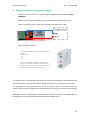
General Description M-DUINO 21 I/Os PLUS product 1
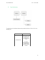
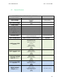
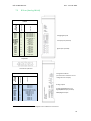
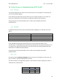
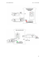
1.1 Zone - Nomenclature
The nomenclature shown in this point will be used in the whole User Guide, so it is
important to understand this nomenclature.
The nomenclature to differentiate the zones is based on the Alphabet, being A the
shield from below and B the shield from above. It has 2 zones (A, B):
The inputs in the zone B are named I0.X, being X any number suitable in the
Shield. Outputs are named as Q0.X.
A ZONE
B ZONE
B ZONE
A ZONE
B ZONE
A ZONE

Ref. IS.MDUINO.21+ Rev. 1: 21-02-2020
13
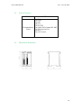
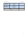
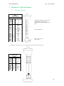
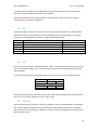
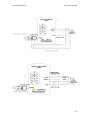
1.2 Zone Distribution
The distribution of the different features that provide the M-Duino 21 I/Os PLUS is the
following one:
Shield
B Zone
Analog Shield
13 Inputs
(13 Digital inputs,
6 of which can
work as Analog
Input)
8 Outputs
(8 Digital Outputs,
3 of which can
work as Analog
Output)

Ref. IS.MDUINO.21+ Rev. 1: 21-02-2020
14
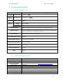
1.3 A Zone Features
Shield
A Zone
Communication
Shield
(1x) Ethernet
(1x) USB
(1x) I2C
(3x) TTL
(1x) RS-232
(1x) HALF/FULL Duplex RS-485
(1x) SPI external Port
(1x) RTC
(1x) uSD Socket
1.4 Mechanical dimension

Ref. IS.MDUINO.21+ Rev. 1: 21-02-2020
15
1.5 General Features
CONECTABLE PLC ARDUINO 24Vcc M-DUINO
MODEL TYPE
A+B Zone
Input Voltage
12 to 24Vdc
Fuse protection (2.5A)
Polarity protection
Input rated voltage
24 Vdc
Rated Power
30 W
I max.
1.5A
Size
101x119.5x119.3
Clock Speed
16MHz
Flash Memory
256KB of which 8KB used by bootloader
SRAM
8KB
EEPROM
4KB
Communications
I2C – Ethernet Port – USB – RS485 – RS232 -- SPI
– (2x) Rx, Tx (Arduino pins)
Max232-Max485-W5500
USB consideration!
Only meant for uploading or debugging, not
always connected as a serial in a project!
Cannot be working in a final
application
An/Dig Input 10bit
(0-10Vcc)
0 to 10Vac
Input Impedance: 39K
Separated PCB ground
Rated Voltage: 10Vac
7 to 24Vdc
I min: 2 to 12 mA
Galvanic Isolation
Rated Voltage: 24 Vdc
Digital Isolated Input
(24Vcc)
7 to 24Vdc
I min: 2 to 12 mA
Galvanic Isolation
Rated Voltage: 24 Vdc
* Interrupt isolated
Input HS (24Vcc)
7 to 24Vdc
I min: 2 to 12 mA
Galvanic Isolation
Rated Voltage: 24Vdc
Analog Output 8bit
(0-10Vcc)
0 to 10Vac
I max: 20 mA
Separated PCB ground
Rated Voltage: 10Vac
Digital Isolated
Output (24Vcc)
5 to 24Vdc
I max: 70 mA
Galvanic Isolation
Diode Protected for Relay
Rated Voltage: 24Vdc
Imax 24Vdc: 410 mA

Ref. IS.MDUINO.21+ Rev. 1: 21-02-2020
16
Digital Isolated
Output Relay
220V Vdc
I max: 5A
Galvanic Isolation
Diode protected for Relay
PWM Isolated Output
8bit (24Vcc)
5 to 24Vdc
I max: 70 mA
Galvanic Isolation
Diode Protected for Relay
Rated Voltage: 24Vdc
Expandability
I2C - 127 elements - Serial Port RS232/RS485
* By using this type of signal can no longer use Digital signal
(24Vdc)

Ref. IS.MDUINO.21+ Rev. 1: 21-02-2020
17
Technical Specifications: 2
2.1 General Specifications:
Item
M-Duino PLC Arduino Ethernet 21 I/Os Analog/Digital PLUS
Power supply
voltage
DC power supply
12 to 24Vdc
Operating
voltage range
DC power supply
11.4 to 25.4Vdc
Power
consumption
DC power supply
30W max.
External
power supply
Power supply
voltage
24Vdc
Power supply
output capacity
700Ma
Insulation resistance
20MΩ min.at 500Vdc between the AC terminals and the protective earth terminal.
Dielectric strength
2.300 VAC at 50/60 Hz for one minute with a leakage current of 10mA max. Between all the
external AC terminals and the protective ground terminal.
Shock resistance
80m/s2 in the X, Y and Z direction 2 times each.
Ambient temperature (operating)
0º to 60ºC
Ambient humidity (operating)
10% to 90% (no condensation)
Ambient environment (operating)
With no corrosive gas
Ambient temperature (storage)
-20º to 60ºC
Power supply holding time
2ms min.
Weight
378g max.
2.2 Performance Specification:
Arduino Board
ARDUINO MEGA 2560
Control method
Stored program method
I/O control method
Combination of the cyclic scan and immediate refresh processing methods.
Programming language
Arduino IDE. Based on wiring (Wiring is an Open Source electronics platform composed of a
programming language. “similar to the C”. http://arduino.cc/en/Tutorial/HomePage
Microcontroller
ATmega2560
Flash Memory
256KB of which 8KB are used by the bootloader
Program capacity (SRAM)
8KB
EEPROM
4KB
Clock Speed
16MHz
Clock Speed
16MHz

Ref. IS.MDUINO.21+ Rev. 1: 21-02-2020
18
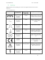
2.3 Symbology
Table that includes all the symbology that is used in the serigraph of the M-Duino PLC Arduino
Ethernet 21
I/Os Analog/Digital PLUS:
Symbol
Standard No. /
Standard Title
Standard
Reference No. /
Symbol Title
Symbol Meaning
IEC 60417 /
Graphical symbols
for use on
equipment
5031 / Direct
Current
Indicates that the equipment is
suitable for direct current only;
to identify relevant terminals
IEC 60417 /
Graphical symbols
for use on
equipment
5032 / Alternating
Current
Indicates that the equipment is
suitable for alternating current
only; to identify relevant
terminals
IEC 60417 /
Graphical symbols
for use on
equipment
5130 / Pulse
General
To identify the control by
which a pulse is started.
IEC 60417 /
Graphical symbols
for use on
equipment
5017 / Earth,
Ground
To identify an earth (ground)
terminal in cases where
neither the symbol 5018 nor
5019 is explicily required.
IEC 60417 /
Graphical symbols
for use on
equipment
5115 / SIgnal lamp
To identify the switch by
means of which the signal
lamp(s) is (are) switched on or
off.
Medical Devices
Directive
93/42/EEC
CE Marking
CE marking indicates that a
product complies with
applicable European Union
regulations
ISO 7000/
Graphical symbols
for use on
equipment
0434B /
Warning symbol
Indicates a potentially
hazardous situation which, if
not avoided, could result in
death or serious injury
ISO 7000/
Graphical symbols
for use on
equipment
5036 / Dangerous
Voltage
To indicate hazards arising
from dangerous voltages

Ref. IS.MDUINO.21+ Rev. 1: 21-02-2020
19
Precautions 3
Read this manual before attempting to use the M-Duino PLC Arduino Ethernet 21 I/Os
Analog/Digital PLUS and follow its descriptions for reference during operation.
3.1 Arduino Board
The M-Duino 21 I/Os PLUS PLCs include Arduino Mega Board as controller.
3.2 Intended Audience
This manual is intended for technicians, which must have knowledge on electrical systems.
3.3 General Precautions
The user must operate M-Duino according to the performance specifications described in this
manual.
Before using M-Duino under different conditions from what has been specified in this manual
or integrating M-Duino to nuclear control systems, railroad systems, aviation systems, vehicles,
combustion systems, medical equipment, amusement machines, safety equipment and other
systems, machines, and equipment that may have a serious influence on lives and property if
used improperly, consult your INDUSTRIAL SHIELDS representative. Ensure that the rating and
performance characteristics of M-Duino are sufficient for the systems, machines, and
equipment, and be sure to provide the systems, machines, and equipment double safety
mechanisms. This manual provides information for programming and operating the M-Duino.
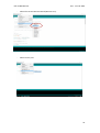
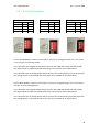
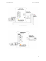
Software interface 4
Industrial Shields PLC are programmed using Arduino IDE, which is a software based on the C
language. They can also be programmed using directly C but it is much easier working with
Arduino IDE as it provides lots of libraries that helps in the programming.
Industrial Shields provides boards for programming the PLCs much easier. Basically it is no
needed to define the pins and if that pins are inputs or outputs. Everything is set up
automatically if using the boards.
In order to install Industrial Shields boards, these are the steps that must be followed.
Requirements:
Arduino IDE 1.8.0 or above (better to have always the latest version).
La page est en cours de chargement...
La page est en cours de chargement...
La page est en cours de chargement...
La page est en cours de chargement...
La page est en cours de chargement...
La page est en cours de chargement...
La page est en cours de chargement...
La page est en cours de chargement...
La page est en cours de chargement...
La page est en cours de chargement...
La page est en cours de chargement...
La page est en cours de chargement...
La page est en cours de chargement...
La page est en cours de chargement...
La page est en cours de chargement...
La page est en cours de chargement...
La page est en cours de chargement...
La page est en cours de chargement...
La page est en cours de chargement...
La page est en cours de chargement...
La page est en cours de chargement...
La page est en cours de chargement...
La page est en cours de chargement...
La page est en cours de chargement...
La page est en cours de chargement...
La page est en cours de chargement...
La page est en cours de chargement...
La page est en cours de chargement...
La page est en cours de chargement...
La page est en cours de chargement...
La page est en cours de chargement...
La page est en cours de chargement...
La page est en cours de chargement...
-
 1
1
-
 2
2
-
 3
3
-
 4
4
-
 5
5
-
 6
6
-
 7
7
-
 8
8
-
 9
9
-
 10
10
-
 11
11
-
 12
12
-
 13
13
-
 14
14
-
 15
15
-
 16
16
-
 17
17
-
 18
18
-
 19
19
-
 20
20
-
 21
21
-
 22
22
-
 23
23
-
 24
24
-
 25
25
-
 26
26
-
 27
27
-
 28
28
-
 29
29
-
 30
30
-
 31
31
-
 32
32
-
 33
33
-
 34
34
-
 35
35
-
 36
36
-
 37
37
-
 38
38
-
 39
39
-
 40
40
-
 41
41
-
 42
42
-
 43
43
-
 44
44
-
 45
45
-
 46
46
-
 47
47
-
 48
48
-
 49
49
-
 50
50
-
 51
51
-
 52
52
-
 53
53


Industrial Shields IS.MDUINO.21+ Mode d'emploi
- Taper
- Mode d'emploi
dans d''autres langues
Documents connexes
-
 Industrial Shields IS.MDUINO.57AAR+ Mode d'emploi
-
 Industrial Shields IS.MDUINO.53ARR+ Mode d'emploi
-
 Industrial Shields IS.MDUINO.50RRA+ Mode d'emploi
-
 Industrial Shields IS.MDUINO.42+ Mode d'emploi
-
 Industrial Shields IS.MDUINO.38R+ Mode d'emploi
-
 Industrial Shields IS.MDUINO.57R+ Manuel utilisateur
-
 Industrial Shields IS.MDUINO.57R+ Mode d'emploi


Autres documents
-
Velleman KA06 Manuel utilisateur
-
Joy-it MotoDriver 3 Manuel utilisateur
-
Blackmagic Studio Camera Manuel utilisateur
-
Multitech MTQN-MNG1-B01.R1 Mode d'emploi
-
-
Multitech MTQ-H5-B01 Mode d'emploi
-
Renkforce renkforce 1897728 Le manuel du propriétaire
-
Conrad Components 10215 Profi Lernpaket Internet of Things Course material 14 years and over Mode d'emploi
-
dji Assistant 2 Mode d'emploi
-
dji Assistant 2 Manuel utilisateur