
En-1
AIR CONDITIONER
PART No. 9374995523
For authorized service personnel only.
OUTDOOR UNIT
INSTALLATION MANUAL

En-1
1. SAFETY PRECAUTIONS
Be sure to read this manual carefully before installation.
The warnings and precautions indicated in this manual contain important information
pertaining to your safety. Be sure to observe them.
Hand this manual, together with the operating manual, to the customer. Request the
customer to keep them on hand for future use, such as for relocating or repairing the unit.
After installation, explain correct operation to the customer, using the operating manual.
WARNING
This mark indicates procedures which, if improperly performed,
might lead to the death or serious injury of the user.
To avoid getting an electric shock, never touch the electrical components soon after
the power supply has been turned off. After turning off the power, always wait 10
minutes or more before you touch the electrical components.
Installation of this product must be done by experienced service technicians or profes-
sional installers only in accordance with this manual. Installation by non-professional
or improper installation of the product might cause serious accidents such as injury,
water leakage, electric shock, or ¿ re. If the product is installed in disregard of the
instructions in this manual, it will void the manufacturer’s warranty.
Do not turn on the power until all work has been completed. Turning on the power be-
fore the work is completed can cause serious accidents such as an electric shock or a
¿ re.
If refrigerant leaks while work is being carried out, ventilate the area. If the refrigerant
comes in contact with a À ame, it produces a toxic gas.
Installation must be performed in accordance with regulations, codes, or standards for
electrical wiring and equipment in each country, region, or the installation place.
Do not use this equipment with air or any other unspeci¿ ed refrigerant in the refriger-
ant lines. Excess pressure can cause a rupture.
During installation, make sure that the refrigerant pipe is attached ¿ rmly before you
run the compressor. Do not operate the compressor under the condition of refrigerant
piping not attached properly with 2-way or 3-way valve open. This may cause abnor-
mal pressure in the refrigeration cycle that leads to breakage and even injury.
When installing and relocating the air conditioner, do not mix gases other than the
speci¿ ed refrigerant (R410A) to enter the refrigerant cycle. If air or other gas enters
the refrigerant cycle, the pressure inside the cycle will rise to an abnormally high value
and cause breakage, injury, etc.
To connect the indoor unit and outdoor unit, use air conditioner piping and cables
available locally as standard parts. This manual describes proper connections using
such installation set.
Do not use an extension cable.
If the supply cord is damaged, it must be replaced by the manufacturer, its service
agent or similarly quali¿ ed persons in order to avoid a hazard.
Do not modify power cable, use extension cable or branch wiring. Improper use may
cause electric shock or ¿ re by poor connection, insuf¿ cient insulation or over current.
Do not purge the air with refrigerants but use a vacuum pump to vacuum the installa-
tion.
There is not extra refrigerant in the outdoor unit for air purging.
Using the same vacuum pump for different refrigerants may damage the vacuum
pump or the unit.
Use a clean gauge manifold, vacuum pump and charging hose for R410A exclusively.
During the pump down operation, make sure that the compressor is turned off before
you remove the refrigerant piping.
Do not remove the connection pipe while the compressor is in operation with 2 way or
3 way valve open. This may cause abnormal pressure in the refrigeration cycle that
leads to rupture and even injury.
This appliance is not intended for use by persons (including children) with reduced
physical, sensory or mental capabilities, or lack of experience and knowledge, unless
they have been given supervision or instruction concerning use of the appliance by a
person responsible for their safety. Children should be supervised to ensure that they
do not play with the appliance.
To avoid danger of suffocation, keep the plastic bag or thin ¿ lm used as the packaging
material away from young children.
When installing this system in high humidity locations, install using ground fault equip-
ment breakers (often referred to in other countries as an ELCB [earth leakage current
breaker]) to reduce the risk of leaking current which may result in electric shock or
potential ¿ re.
CAUTION
This mark indicates procedures which, if improperly performed,
might possibly result in personal harm to the user, or damage
to property.
Do not attempt to install the air conditioner or a part of the air conditioner by yourself.
This product must be installed by quali¿ ed personnel with a capacity certi¿ cate for
handling refrigerant À uids. Refer to regulation and laws in use on installation place.
Installation work must be performed in accordance with national wiring standards by
authorized personnel only.
Install the product by following local codes and regulations in force at the place of
installation, and the instructions provided by the manufacturer.
Connect the indoor unit and outdoor unit with the air conditioner piping and cables
available standards parts. This installation manual describes the correct connections
using the installation set available from our standard parts.
After a long period of disuse in an environment 0 °C or lower, supply power to the unit
at least 12 hours before re-starting the unit.
This product is part of a set constituting an air conditioner. The product must not be
installed alone or be installed with non-authorized device by the manufacturer.
Always use a separate power supply line protected by a circuit breaker operating on
all wires with a distance between contact of 3 mm for this product.
To protect the persons, earth (ground) the product correctly, and use the power cable
combined with an Earth Leakage Circuit Breaker (ELCB).
This product is not explosion proof, and therefore should not be installed in explosive
atmosphere.
Do not touch the ¿ ns of the heat exchanger. Touching the heat exchanger ¿ ns could
result in damage to the ¿ ns or personal injury such as skin rupture.
This product contains no user-serviceable parts. Always consult experienced service
technicians for repairing.
When moving or relocating the air conditioner, consult experienced service techni-
cians for disconnection and reinstallation of the product.
Do not place any other electrical products or household belongings under indoor unit
or outdoor unit. Dripping condensation from the unit might get them wet, and may
cause damage or malfunction of your property.
Children should be monitored to ensure they do not play with the device.
Contents
1. SAFETY PRECAUTIONS ……………………………………………………………… 1
2. ABOUT THIS PRODUCT ………………………………………………………………… 2
2. 1. Precautions for using R410A refrigerant …………………………………………2
2. 2. Special tools for R410A refrigerant ……………………………………………… 2
2. 3. Accessories ………………………………………………………………………… 2
2. 4. Optional parts ……………………………………………………………………… 2
2. 5. System con¿ guration ……………………………………………………………… 2
3. GENERAL SPECIFICATIONS ……………………………………………………………3
3. 1. Power ………………………………………………………………………………… 3
3. 2. Selecting circuit breaker and wiring ………………………………………………4
3. 3. Selecting the pipe material …………………………………………………………4
3. 4. Heat insulation around connection pipes requirements ………………………… 4
3. 5. Operating range ……………………………………………………………………4
3. 6. Additional charging ………………………………………………………………… 4
4. INSTALLATION WORK …………………………………………………………………4
4. 1. Selecting an installation location ………………………………………………… 4
4. 2. Installation dimensions ……………………………………………………………5
4. 3. Placing the unit ……………………………………………………………………… 6
4. 4. Drain installation …………………………………………………………………… 6
4. 5. Secure the unit ………………………………………………………………………6
5. PIPE INSTALLATION …………………………………………………………………… 7
5. 1. Pipe connection …………………………………………………………………… 7
5. 2. Sealing test ………………………………………………………………………… 8
5. 3. Vacuum process …………………………………………………………………… 9
6. ELECTRICAL WIRING ……………………………………………………………………9
6. 1. Notes for electrical wiring …………………………………………………………9
6. 2. Connection diagrams …………………………………………………………… 10
6. 3. Wiring method …………………………………………………………………… 10
6. 4. Connecting the Central remote controller (Option) …………………………… 12
7. DEMAND CONTROL ………………………………………………………………… 12
7. 1. Preparation for installation ……………………………………………………… 12
7. 2. How to connect …………………………………………………………………… 12
8. HOW TO OPERATE DISPLAY UNIT ………………………………………………… 13
8. 1. Various setting methods ………………………………………………………… 13
8. 2. Outdoor unit low noise operation function (option) …………………………… 14
8. 3. Changing the current limit function …………………………………………… 14
9. CHECK RUN …………………………………………………………………………… 14
9. 1. Things to con¿ rm before starting the check run. ……………………………… 14
9. 2. Restrictions applicable when performing the check run ……………………… 14
9. 3. Operating procedure for check run …………………………………………… 15
9. 4. Check run judgment failure display …………………………………………… 17
9. 5. Re-display check run results …………………………………………………… 17
9. 6. Automatic wiring correction memory reset …………………………………… 17
10. TEST RUN ……………………………………………………………………………… 17
10. 1. TEST RUN method ……………………………………………………………… 17
11. ERROR CODE ………………………………………………………………………… 18
11. 1. In the event of an error ………………………………………………………… 18
11. 2. Error location display …………………………………………………………… 18
11. 3. Error code display ……………………………………………………………… 18
12. PUMP DOWN…………………………………………………………………………… 18
13. CUSTOMER GUIDANCE ……………………………………………………………… 19
INSTALLATION MANUAL
PART No. 9374995523
Outdoor Unit

En-2
2. ABOUT THIS PRODUCT
2. 1. Precautions for using R410A refrigerant
WARNING
The basic installation work procedures are the same as conventional refrigerant (R22)
models.
However, pay careful attention to the following points:
• Since the working pressure is 1.6 times higher than that of conventional refrigerant
(R22) models, some of the piping and installation and service tools are special. (See
the table below.)
Especially, when replacing a conventional refrigerant (R22) model with a new refrig-
erant R410A model, always replace the conventional piping and À are nuts with the
R410A piping and À are nuts.
• Models that use refrigerant R410A have a different charging port thread diameter
to prevent erroneous charging with conventional refrigerant (R22) and for safety.
Therefore, check beforehand. [The charging port thread diameter for R410A is 1/2-
20 UNF.]
• Be careful that foreign matter (oil, water, etc.) does not enter the piping than with re-
frigerant models. Also, when storing the piping, securely seal the openings by pinch-
ing, taping, etc.
• When charging the refrigerant, take into account the slight change in the composition
of the gas and liquid phases, and always charge from the liquid phase side whose
composition is stable.
2. 2. Special tools for R410A refrigerant
Tool name
Contents of change
Gauge manifold
Pressure is high and cannot be measured with a conventional
gauge. To prevent erroneous mixing of other refrigerants, the
diameter of each port has been changed.
It is recommended the gauge with seals -0.1 to 5.3 MPa (30 in.
Hg to 769 psi) for high pressure. -0.1 to 3.8 MPa (30 in. Hg to
551 psi) for low pressure.
Charge hose
To increase pressure resistance, the hose material and base
size were changed.
Vacuum pump
A conventional vacuum pump can be used by installing a
vacuum pump adapter.
Be sure that the pump oil does not back À ow into the system.
Use one capable for vacuum suction of -100.7 kPa (5 Ton, -755
mmHg).
Gas leakage
detector
Special gas leakage detector for HFC refrigerant R410A.
Copper pipes
It is necessary to use seamless copper pipes and it is desirable that the amount of re-
sidual oil is less than 40 mg/10 m. Do not use copper pipes having a collapsed, deformed
or discolored portion (especially on the interior surface). Otherwise, the expansion valve
or capillary tube may become blocked with contaminants.
As an air conditioner using R410A incurs pressure higher than when using conventional
refrigerant, it is necessary to choose adequate materials.
Thicknesses of copper pipes used with R410A are as shown in the table. Never use cop-
per pipes thinner than that in the table even when it is available on the market.
Thicknesses of Annealed Copper Pipes (R410A)
Pipe outside diameter [mm (in.)] Thickness [mm (in.)]
6.35 (1/4) 0.80 (0.032)
9.52 (3/8) 0.80 (0.032)
12.70 (1/2) 0.80 (0.032)
15.88 (5/8) 1.00 (0.039)
19.05 (3/4) 1.20 (0.047)
2. 3. Accessories
WARNING
For installation purposes, be sure to use the parts supplied by the manufacturer or
other prescribed parts. The use of non-prescribed parts can cause serious accidents
such as the unit falling, water leakage, electric shock, or ¿ re.
Do not throw away the connecting parts until the installation has been complete.
Name and shape Q’ty Application
Installation
manual
1
(This book)
Name and shape Q’ty Application
Drain cap
7
For outdoor unit drain
piping work
[45 type only]
Drain pipe
1
Adapter [mm (in.)]
K: [12.70 (1/2) ĺ 9.52 (3/8)] × 2
L: [12.70 (1/2) ĺ 15.88 (5/8)] × 2
H: [9.52 (3/8) ĺ 12.70 (1/2)] × 1
K
K
L
L
H
1 set
Adapter is necessary
in the connection of the
indoor unit.
For more information,
refer to the installation
manual included with the
indoor unit.
[45 type]
Adapter [mm (in.)]
K: [12.70 (1/2) ĺ 9.52 (3/8)] × 1
L: [12.70 (1/2) ĺ 15.88 (5/8)] × 1
H: [9.52 (3/8) ĺ 12.70 (1/2)] × 1
KL H
1 set
Adapter is necessary
in the connection of the
indoor unit.
For more information,
refer to the installation
manual included with the
indoor unit.
[36 type]
Cable tie with clip
Large: 2
For binding wire with
connector
(For conduit plate)
Small: 2
For binding wire with
connector
Cable tie
1
For binding wire with
connector
Operating
manual
1
Instruction manual
(Demand)
Grommet edging
1
For Connection cable
installation.
Attach to the knockout
hole.
2. 4. Optional parts
Parts name Model name
Central remote controller UTY-DMMYM
2. 5. System con¿ guration
Layout example for the indoor units and outdoor unit
Valve cover removal
· Remove the six mounting screws.
· Remove the valve cover.

En-3
2. 5. 1. Connectable indoor unit capacity type (Outdoor unit: 45 type)
A
B
C
D
F
E
H1
H1
H2
Power source
240 V ~ 50 Hz
Power supply
cable
Connection
cable
Refrigerant pipe
OUTDOOR UNIT
INDOOR UNITS
UNIT E
7-9
UNIT D
7-12
UNIT C
7-18
UNIT B
7-24
UNIT A
7-24
UNIT F
7-9
CAUTION
The total capacity of the indoor units connected must be between 34,000 and 62,000
BTU.
Connection patterns are restricted. Normal operation is not guaranteed if connected
pattern in the combination not listed below. The product may be damaged. Surely con-
nect in accordance with the combination in the following connection pattern.
• To install an indoor unit, refer to the installation manual included with the indoor unit.
Outdoor port
Capacity indoor unit
Standard port size [mm (in.)]
F 6.35 (1/4) / 9.52 (3/8) 7 - 9
E 6.35 (1/4) / 9.52 (3/8) 7 - 9
D 6.35 (1/4) / 9.52 (3/8) 7 - 12
C 6.35 (1/4) / 9.52 (3/8) 7 - 18
B 6.35 (1/4) / 12.70 (1/2) 7 - 24
A 6.35 (1/4) / 12.70 (1/2) 7 - 24
Port F: Ø6.35 mm, Ø9.52 mm (Ø1/4 in., Ø3/8 in.)
Port E: Ø6.35 mm, Ø9.52 mm (Ø1/4 in., Ø3/8 in.)
Port D: Ø6.35 mm, Ø9.52 mm (Ø1/4 in., Ø3/8 in.)
Port C: Ø6.35 mm, Ø9.52 mm (Ø1/4 in., Ø3/8 in.)
Port B: Ø6.35 mm, Ø12.70 mm (Ø1/4 in., Ø1/2 in.)
Port A: Ø6.35 mm, Ø12.70 mm (Ø1/4 in., Ø1/2 in.)
2. 5. 2. Connectable indoor unit capacity type (Outdoor unit: 36 type)
A
B
C
D
E
H1
H1
H2
Power source
240 V ~ 50 Hz
Power supply
cable
Connection
cable
Refrigerant pipe
OUTDOOR UNIT
INDOOR UNITS
UNIT E
7-9
UNIT D
7-12
UNIT C
7-18
UNIT B
7-24
UNIT A
7-24
CAUTION
The total capacity of the indoor units connected must be between 27,000 and 54,000
BTU.
Connection patterns are restricted. Normal operation is not guaranteed if connected
pattern in the combination not listed below. The product may be damaged. Surely con-
nect in accordance with the combination in the following connection pattern.
• To install an indoor unit, refer to the installation manual included with the indoor unit.
Outdoor port
Capacity indoor unit
Standard port size [mm (in.)]
E 6.35 (1/4) / 9.52 (3/8) 7 - 9
D 6.35 (1/4) / 9.52 (3/8) 7 - 12
C 6.35 (1/4) / 9.52 (3/8) 7 - 18
B 6.35 (1/4) / 12.70 (1/2) 7 - 24
A 6.35 (1/4) / 12.70 (1/2) 7 - 24
Port E: Ø6.35 mm, Ø9.52 mm (Ø1/4 in., Ø3/8 in.)
Port D: Ø6.35 mm, Ø9.52 mm (Ø1/4 in., Ø3/8 in.)
Port C: Ø6.35 mm, Ø9.52 mm (Ø1/4 in., Ø3/8 in.)
Port B: Ø6.35 mm, Ø12.70 mm (Ø1/4 in., Ø1/2 in.)
Port A: Ø6.35 mm, Ø12.70 mm (Ø1/4 in., Ø1/2 in.)
2. 5. 3. Limitation of refrigerant piping length
CAUTION
The total maximum pipe lengths and height difference of this product are shown in the
table.
If the units are further apart than this, correct operation cannot be guaranteed.
Total max. length *1)
45 type (a+b+c+d+e+f)
80 m
36 type (a+b+c+d+e)
Max. length for each indoor unit
45 type (a, b, c, d, e or f)
25 m
36 type (a, b, c, d or e)
"Max. height difference between
outdoor unit and each indoor unit"
(H1) 15 m
"Max. height difference between indoor
units"
(H2) 10 m
Min. length for each indoor unit
45 type (a, b, c, d, e or f)
5 m
36 type (a, b, c, d or e)
Total min. length
(a+b) 15 m
)
*1) If the total piping is longer than 50 m, additional refrigerant charging is necessary. (For
more information, refer to “3.6. Additional charging”.)
3. GENERAL SPECIFICATIONS
3. 1. Power
WARNING
The rated voltage of this product is 240 V A.C. 50 Hz.
Before turning on verify that the voltage is within the 198 V to 264 V range.
Always use a special branch circuit and install a special receptacle to supply power to
the air conditioner.
Use a special branch circuit breaker and receptacle matched to the capacity of the air
conditioner. (Install in accordance with standard.)
Do not extend the power cord.
Perform wiring work in accordance with standards so that the air conditioner can be
operated safely and positively.
Install a leakage special branch circuit breaker in accordance with the related laws
and regulations and electric company standards.

En-4
CAUTION
The power source capacity must be the sum of the air conditioner current and the
current of other electrical appliances. When the current contracted capacity is insuf-
¿ cient, change the contracted capacity.
When the voltage is low and it is dif¿ cult to start the air conditioner, contact the power
company to have the voltage raised.
3. 2. Selecting circuit breaker and wiring
CAUTION
Be sure to install a breaker of the speci¿ ed capacity.
Regulation of cables and breaker differs from each locality, refer in accordance with
local rules.
Voltage rating
1ø 240V (50Hz)
Operating range
198-264V
Cable Cable size (mm
2
)
*1
Type Remarks
Power supply cable 6.0
Type 60245
IEC 66
2 cable + Earth (Ground),
1 Ø 240V
Connection cable 1.5
Type 60245
IEC 57
3 cable + Earth (Ground),
1 Ø 240V
Cable Cable size
*1)
Remarks
Remote controller cable
*2)
0.33 mm²
Use shield cable in accordance
with local rules for cable. (Polar
3 core)
*1) Selected sample: Select the correct cable type and size according to the country or
region’s regulations.
Max. wire length: Set a length so that the voltage drop is less than 2%. Increase the
wire diameter when the wire length is long.
*2) The remote controller cable supplied with the Central remote controller is for indoor
use. If you require cables for outdoor use, please purchase locally. Material is not
speci¿ ed. However, it should be selected considering the operating environment (tem-
perature, humidity), and regional regulations (ROHS Directive, etc.).
Breaker Speci¿ cation
*3)
Circuit breaker
45 type Current : 30(A)
36 type Current : 25(A)
Earth leakage breaker Leakage current : 30mA 0.1sec or less
*4)
*3) Select the appropriate breaker of the described speci¿ cation according to the national
or regional standards.
*4) Select the breaker that enough load current can pass through it.
3. 3. Selecting the pipe material
CAUTION
Do not use existing pipes.
Use pipes that have clean external and internal sides without any contamination which
may cause trouble during use, such as sulphur, oxide, dust, cutting waste, oil, or wa-
ter.
It is necessary to use seamless copper pipes.
Material: Phosphor deoxidized seamless copper pipes.
It is desirable that the amount of residual oil is less than 40 mg/10 m.
Do not use copper pipes that have a collapsed, deformed, or discoloured portion
(especially on the interior surface). Otherwise, the expansion valve or capillary tube
may become blocked with contaminants.
Improper pipe selection will degrade performance. As an air conditioner using R410A
incurs pressure higher than when using conventional refrigerant, it is necessary to
choose adequate materials.
The diameters of the connection pipes differ according to the capacity of the indoor unit.
Refer to the following table for the proper diameters of the connection pipes between the
indoor and outdoor units.
Capacity of indoor
unit
Gas pipe size
(thickness)
mm (mm)
Liquid pipe size
(thickness)
mm (mm)
7 – 12 ø9.52 (0.8) ø6.35 (0.8)
15, 18 ø12.70 (0.8) ø6.35 (0.8)
24 ø15.88 (1.0) ø6.35 (0.8)
CAUTION
Operation cannot be guaranteed if the correct combination of pipes, valves, etc., is not
used to connect the indoor and outdoor units.
3. 4. Heat insulation around connection pipes requirements
CAUTION
Install heat insulation around both the gas and liquid pipes.
Failure to do so may cause water leaks.
Use heat insulation with heat resistance above 120 °C. (Reverse cycle model only)
In addition, if the humidity level at the installation location of the refrigerant piping is
expected to exceed 70%, install heat insulation around the refrigerant piping. If the
expected humidity level is 70-80%, use heat insulation that is 15 mm or thicker and if
the expected humidity exceeds 80%, use heat insulation that is 20 mm or thicker.
If heat insulation is used that is not as thick as speci¿ ed, condensation may form on
the surface of the insulation. In addition, use heat insulation with heat conductivity of
0.045 W/(m·K) or less at 20 °C.
Connect the connection pipes according to “5.1. Pipe connection” in this installation manual.
3. 5. Operating range
Temperature Indoor air intake Outdoor air intake
Cooling
Maximum 32.0 °C DB 46.0 °C DB
Minimum 18.0 °C DB -10.0 °C DB
Heating
Maximum 30.0 °C DB 24.0 °C DB
Minimum 16.0 °C DB -15.0 °C DB
Indoor humidity about 80% or less
3. 6. Additional charging
Refrigerant suitable for a total piping length of 50 m is charged in the outdoor unit at the
factory.
When the piping is longer than 50 m, additional charging is necessary.
For the additional amount, see the table below.
Total piping length (m)
50 or less 60 70 80
Additional refrigerant charge
None 200 g 400 g 600 g 20 g/m
CAUTION
When moving and installing the air conditioner, do not mix gas other than the speci¿ ed
refrigerant (R410A) inside the refrigerant cycle.
When charging the refrigerant R410A, always use an electronic balance for refrigerant
charging (to measure the refrigerant by weight).
When charging the refrigerant, take into account the
slight change in the composition of the gas and liquid
phases, and always charge from the liquid phase side
whose composition is stable.
R410A
Gas
Liquid
Add refrigerant from the charging valve after the completion of the work.
If the units are further apart than the maximum pipe length, correct operation cannot
be guaranteed.
4. INSTALLATION WORK
Please obtain the approval of the customer when selecting the location of installation and
installing the unit.
4. 1. Selecting an installation location
WARNING
Securely install the outdoor unit at a location that can withstand the weight of the unit.
Otherwise, the outdoor unit may fall and cause injury.
Be sure to install the outdoor unit as prescribed, so that it can withstand earthquakes
and typhoons or other strong winds. Improper installation can cause the unit to topple
or fall, or other accidents.
Do not install the outdoor unit near the edge of a balcony. Otherwise, children may
climb onto the outdoor unit and fall off of the balcony.

En-5
CAUTION
Do not install the outdoor unit in the following areas:
• Area with high salt content, such as at the seaside. It will deteriorate metal parts,
causing the parts to fail or the unit to leak water.
• Area ¿ lled with mineral oil or containing a large amount of splashed oil or steam,
such as a kitchen. It will deteriorate plastic parts, causing the parts to fail or the
unit to leak water.
• Area that generates substances that adversely affect the equipment, such as
sulfuric gas, chlorine gas, acid, or alkali. It will cause the copper pipes and brazed
joints to corrode, which can cause refrigerant leakage.
• Area containing equipment that generates electromagnetic interference. It will
cause the control system to malfunction, preventing the unit from operating nor-
mally.
• Area that can cause combustible gas to leak, contains suspended carbon ¿ bers or
À ammable dust, or volatile inÀ ammables such as paint thinner or gasoline. If gas
leaks and settles around the unit, it can cause a ¿ re.
• Area that has heat sources, vapors, or the risk of the leakage of À ammable gas in
the vicinity.
• Area where small animals may live. It may cause failure, smoke or ¿ re if small
animals enter and touch internal electrical parts.
• Area where animals may urinate on the unit or ammonia may be generated.
Please install the outdoor unit without slant.
Install the outdoor unit in a well-ventilated location away from rain or direct sunlight.
If the outdoor unit must be installed in an area within easy reach of the general public,
install as necessary a protective fence or the like to prevent their access.
Install the outdoor unit in a location that would not inconvenience your neighbors, as
they could be affected by the airÀ ow coming out from the outlet, noise, or vibration. If it
must be installed in proximity to your neighbors, be sure to obtain their approval.
If the outdoor unit is installed in a cold region that is affected by snow accumulation,
snow fall, or freezing, take appropriate measures to protect it from those elements. To
ensure a stable operation, install inlet and outlet ducts.
Install the outdoor unit in a location that is away from exhaust or the vent ports that
discharge vapor, soot, dust, or debris.
Install the indoor unit, outdoor unit, power supply cable, connection cable, and remote
control cable at least 1 m away from a television or radio receivers. The purpose of
this is to prevent TV reception interference or radio noise. (Even if they are installed
more than 1 m apart, you could still receive noise under some signal conditions.)
Branch switch and
circuit breaker
Branch switch and
circuit breaker
1 m or more
1 m or more
If children under 10 years old may approach the unit, take preventive measures so
that they cannot reach the unit.
Keep the length of the piping of the indoor and outdoor units within the allowable
range.
For maintenance purposes, do not bury the piping.
4. 2. Installation dimensions
CAUTION
Install the unit where it will not be tilted by more than 3Û. However, do not install the
unit with it tilted towards the side containing the compressor.
When installing the outdoor unit where it may exposed to strong wind, fasten it se-
curely.
Decide the mounting position with the customer as follows:
(1) Install the outdoor unit in a location which can withstand the weight of the unit and
vibration, and which can install horizontally.
(2) Provide the indicated space to ensure good airÀ ow.
(3) If possible, do not install the unit where it will be exposed to direct sunlight.
(If necessary, install a blind that does not interfere with the airÀ ow.)
(4) Do not install the unit near a source of heat, steam, or À ammable gas.
(5) During heating operation, drain water À ows from the outdoor unit.
Therefore, install the outdoor unit in a place where the drain water À ow will not be
obstructed. (Reverse cycle model only)
(6) Do not install the unit where strong wind blows or where it is very dusty.
(7) Do not install the unit where people pass.
(8) Install the outdoor unit in a place where it will be free from being dirty or getting wet by
rain as much as possible.
(9) Install the unit where connection to the indoor unit is easy.
4. 2. 1. Single outdoor unit installation
When the upper space is open:
(Unit: mm)
(1) When there are obstacles at the
rear only.
150 or more
(2) When there are obstacles at the
rear and sides.
200 or more
250 or more
300 or more
(3) When there are obstacles at the
front only.
1000 or more
(4) When there are obstacles at the
front and rear.
1000 or more
150 or more
When there is an obstruction in the upper space:
(Unit: mm)
(1) When there are obstacles at the
rear and above.
Max. 500
300 or more
1000 or more
(2) When there are obstacles at the rear, sides,
and above.
1000 or more
500 or more
200 or more
250 or more
Max. 500
4. 2. 2. Multiple outdoor unit installation
• Provide at least 25 mm of space between the outdoor units if multiple units are
installed.
• When routing the piping from the side of an outdoor unit, provide space for the piping.
• No more than 3 units must be installed side by side.
When 3 units or more are arranged in a line, provide the space as shown in the
following example when there is an obstruction in the upper space:
When the upper space is open:
(Unit: mm)
(1) When there are obstacles at the
rear only.
300 or more
250 or more
(2) When there are obstacles at the front
only.
250 or more
1500 or more
(3) When there are obstacles at the front and rear.
500 or more
1500 or more
250 or more

En-6
When there is an obstruction in the upper space:
(Unit: mm)
• When there are obstacles at the rear and above.
1500 or more
500 or more
Max. 300
1500 or more
250 or more
4. 2. 3. Outdoor units installation in multi row
(Unit: mm)
* The following settings are not recommended in case of cooling in a low outside
temperature.
(1) Single parallel unit arrangement
500 or more
600 or more
1500 or more
3000 or more
(2) Multiple parallel unit arrangement
500 or more
600 or more
1500 or more
3500 or more
250 or more
250 or more
250 or more
1500 or more
500 or more
4. 3. Placing the unit
WARNING
Do not touch the ¿ ns. Otherwise, personal injury could result.
CAUTION
When carrying the unit, hold the handles on the right and left sides and be careful. If
the outdoor unit is carried from the bottom, hands or ¿ ngers may be pinched.
• Be sure to hold the handles on the sides of the unit. Otherwise, holding the suction
grille on the sides of the unit may cause deformation.
Handle
Handle
Handle
4. 4. Drain installation
45 type
CAUTION
• Perform drain work in accordance with this Manual, and ensure that the drain water
is properly drained. If the drain work is not carried out correctly, water may drip down
from the unit, wetting the furniture.
• When the outdoor temperature is 0 °C or less, do not use the accessory drain pipe
and drain cap. If the drain pipe and drain cap are used, the drain water in the pipe
may freeze in extremely cold weather. (Reverse cycle model only).
• As the drain water À ows out of the outdoor unit during heating operation, install the
drain pipe and connect it to a commercial 16 mm hose. (Reverse cycle model only)
• When installing the drain pipe, plug all the holes other than the drain pipe mounting
hole in the bottom of the outdoor unit with putty so there is no water leakage. (Reverse
cycle model only)
(Unit: mm)
Drain cap mounting hole × 7
Drain pipe mounting
hole × 1
140
227
296
305
40
315
321
341
50
278
438
76
526
622
690
Drain pipe mounting hole
Base
Drain pipe
4. 5. Secure the unit
WARNING
When installing the outdoor unit where it may exposed to strong wind, fasten it secure-
ly.
• Please install the outdoor unit without slant. (within 3 degrees )
• Install 4 anchor bolts at the locations indicated with arrows in the ¿ gure.
• To reduce vibration, do not install the unit directly on the ground. Install it on a secure
base (such as concrete blocks).
• The foundation shall support the legs of the unit and have a width of 50 mm or more.
• Depending on the installation conditions, the outdoor unit may spread its vibration
during operation, which may cause noise and vibration. Therefore, attach damping
materials (such as damping pads) to the outdoor unit during installation.
• Install the foundation, making sure that there is enough space for installing the
connection pipes.
• Secure the unit to a solid block using foundation bolts. (Use 4 sets of commercially
available M10 bolts, nuts, and washers.)
• The bolts should protrude 20 mm. (Refer to the ¿ gure.)
• If overturning prevention is required, purchase the necessary commercially available
items.

En-7
166
AIR
650 154
50 50
16
410
(Unit: mm)
Bolt
20
Nut
Base
• Do not install directly on the ground, this may re-
sult in equipment failure. Make sure the height of
the base is 50 mm from the ground. Otherwise,
there is a risk that the drainage water will freeze
between the device and the surface, disabling
drainage.
50 mm or over
CAUTION
In areas with heavy snowfall , where intake and outlet of the outdoor unit can become
blocked by snow. It is recommended that unit be installed under a canopy or elevated
on a high stand.
Failure to do so will result in poor heating performance and/or premature failure of
equipment.
In places where the outdoor temperature drops to 0 °C or lower, the drain water may
freeze and may stop up the drain or cause other outdoor unit trouble. Therefore take
measures so that the drain water will not freeze and clog the drain.
Please set up the outdoor unit in a high place and please do not arrange the frame of
installed stand under the drain port, because the water dropped from the drain port
repeats freezing and accumulating, and may block the drain port.
5. PIPE INSTALLATION
5. 1. Pipe connection
CAUTION
Do not use mineral oil on a À ared part. Prevent mineral oil from getting into the system
as this would reduce the lifetime of the units.
While welding the pipes, be sure to blow dry nitrogen gas through them.
The maximum lengths of this product are shown in the table. If the units are further
apart than this, correct operation cannot be guaranteed.
5. 1. 1. Flaring
• Use special pipe cutter and À are tool exclusive for R410A.
(1) Cut the connection pipe to the necessary length with a pipe cutter.
(2) Hold the pipe downward so that the cuttings will not enter the pipe and remove
any burrs.
(3) Insert the À are nut (always use the À are nut attached to the indoor and outdoor
units respectively) onto the pipe and perform the À are processing with a À are tool.
Leakage of refrigerant may result if other À are nuts are used.
(4) Protect the pipes by pinching them or with tape to prevent dust, dirt, or water
from entering the pipes.
L
Check if [L] is À ared uniformly
and is not cracked or scratched.
Pipe
A
B
Die
Pipe outside
diameter [mm (in.)]
Dimension A [mm (in.)]
Dimension B
0
- 0.4
(mm)
Flare tool for R410A,
clutch type
6.35 (1/4)
0 to 0.5 (0 to 0.020)
9.1
9.52 (3/8) 13.2
12.70 (1/2) 16.6
15.88 (5/8) 19.7
19.05 (3/4) 24.0
• When using conventional À are tools to À are R410A pipes, the dimension A should
be approximately 0.5 mm more than indicated in the table (for À aring with R410A
À are tools) to achieve the speci¿ ed À aring. Use a thickness gauge to measure the
dimension A.
Pipe outside
diameter
[mm (in.)]
Width across À ats
of Flare nut
(mm)
6.35 (1/4) 17
9.52 (3/8) 22
12.70 (1/2) 26
15.88 (5/8) 29
19.05 (3/4) 36
Width across À ats
5. 1. 2. Bending pipes
CAUTION
To prevent breaking of the pipe, avoid sharp bends. Bend the pipe with a radius of
curvature of 100 mm or more.
If the pipe is bent repeatedly at the same place, it will break.
• If pipes are shaped by hand, be careful not to collapse them.
• Do not bend the pipes at an angle of more than 90°.
• When pipes are repeatedly bent or stretched, the material will harden, making it
dif¿ cult to bend or stretch them any more.
• Do not bend or stretch the pipes more than 3 times.
5. 1. 3. Connecting pipes
CAUTION
Be sure to install the pipe against the port on the indoor unit and the outdoor unit
correctly. If the centering is improper, the flare nut cannot be tightened smoothly.
If the À are nut is forced to turn, the threads will be damaged.
Do not remove the À are nut from the outdoor unit pipe until immediately before con-
necting the connection pipe.
After installing the piping, make sure that the connection pipes do not touch the com-
pressor or outer panel. If the pipes touch the compressor or outer panel, they will
vibrate and produce noise.
If there are a large number of À are connections due to the number of indoor units con-
nected, please con¿ rm that the valves that are not connected are closed.
Not doing so may cause a refrigerant leak.
When connecting the indoor unit, it should be connected in the order of port A, B, C,
and so on. Please be sure to close remaining unconnected ports so that they do not
leak refrigerant.

En-8
(1) Detach the caps and plugs from the pipes.
(2) Center the pipe against the port on the outdoor unit, and then turn the À are nut
by hand.
To prevent gas leakage, coat the À are
surface with alkylbenzene oil (HAB).
Do not use mineral oil.
(3) Attach the connection pipe.
Example: 45 type
Connection pipe
(Liquid)
Connection pipe
(Gas)
Flare nut
Valve (Liquid)
Valve (Gas)
Port A
Port B
Port C
Port D
Port E
Port F
Holding
wrench
Insulation of the
connection pipe
Torque wrench
Body side
Flare nut
With this model, the Holding wrench
can only be inserted horizontally.
To prevent condensation
from dropping, insulate the
gap between the À are nut
and the insulation of the
connection pipe.
(4) When the À are nut is tightened properly by your hand, use a torque wrench to
¿ nally tighten it.
CAUTION
Hold the torque wrench at its grip, keeping it in a right angle with the pipe, in order to
tighten the À are nut correctly.
• Outer panel may be distorted if fastened only with a wrench. Be sure to ¿ x the
elementary part with a holding wrench and fasten with a torque wrench (refer to below
diagram). Do not apply force to the blank cap of the valve or hang a wrench, etc., on the
cap. If blank cap is broken, it may cause leakage of refrig
erant.
Flare nut [mm (in.)] Tightening torque [N·m (kgf·cm)]
6.35 (1/4) dia. 16 to 18 (160 to 180)
9.52 (3/8) dia. 32 to 42 (320 to 420)
12.70 (1/2) dia. 49 to 61 (490 to 610)
15.88 (5/8) dia. 63 to 75 (630 to 750)
19.05 (3/4) dia. 90 to 110 (900 to 1100)
5. 1. 4. Handling precautions for the valves
• Mounted part of Blank cap is sealed for protection.
• Fasten blank cap tightly after opening valves.
Operating the valves
• Use a hexagon wrench (size: 4 mm).
• Opening (1) Insert the hexagon wrench into the valve shaft, and turn it
counterclockwise.
(2) Stop turning when the valve shaft can no longer be turned.
(Open position)
• Closing (1) Insert the hexagon wrench into the valve shaft, and turn it
clockwise.
(2) Stop turning when the valve shaft can no longer be turned.
(Closed position)
Opening direction
Hexagon wrench
Seal (blank cap
installation portion)
Liquid pipe
Gas pipe
Opening direction
5. 1. 5. How to use adapter (Connection ports of outdoor unit)
• When using the ADAPTER, be careful not to overtighten the nut, or the smaller pipe
may be damaged.
• Apply a coat of refrigeration oil to the threaded connection port of the outdoor unit
where the À are nut comes in.
• Use appropriate wrenches to avoid damaging the connection thread by
overtightening the À are nut.
• Apply wrenches on both of À are nut (local part), and ADAPTER to tighten them.
Adapter tightening torque
Adapter type [mm (in.)] Tightening torque [N·m (kgf·cm)]
ø12.70 (ø1/2) ĺ ø9.52 (ø3/8) 49 to 61 (490 to 610)
ø12.70 (ø1/2) ĺ ø15.88 (ø5/8) 49 to 61 (490 to 610)
5. 2. Sealing test
CAUTION
Use only nitrogen gas.
Never use refrigerant gas, oxygen, in À ammable gas or poisonous gas to pressurize
the system. (If oxygen is used, there is the danger of an explosion.)
Do not apply shock during sealing test.
It can rupture the pipes and cause serious injury.
Do not turn on the power unless all operations are complete.
Do not block the walls and the ceiling until the sealing test and the charging of the
refrigerant gas have been completed.
After connecting the pipes, perform an sealing test.
Recheck that the 3-way valve are closed before performing a sealing test.
(Fig. B)
Pour nitrogen gas through both the liquid pipe and the gas pipe.
Pressurize nitrogen gas to 4.2 MPa to perform the sealing test.
Check all À are connection areas and brazed areas.
Then, check that the pressure has not decreased.
Compare the pressures after pressurizing and letting it stand for 24 hours, and check
that the pressure has not decreased.
* When the outdoor temperature changes 5 °C, the test pressure changes 0.05 MPa.
If the pressure has dropped, the pipe joints may be leaking.
If a leakage is found, immediately repair it and perform a sealing test again.
* Decrease the pressure of nitrogen gas before blazing
After completing the sealing test, release the nitrogen gas from both valves.
Release the nitrogen gas slowly.

En-9
5. 3. Vacuum process
CAUTION
Do not turn on the power unless all operations are complete.
If the system is not evacuated suf¿ ciently, its performance will drop.
Be sure to evacuate the refrigerant system using a vacuum pump.
The refrigerant pressure may sometimes not rise when a closed valve is opened after
the system is evacuated using a vacuum pump. This is caused by the closure of the
refrigerant system of the outdoor unit by the electronic expansion valve. This will not
affect the operation of the unit.
Use a clean gauge manifold and charging hose that were designed speci¿ cally for
use with R410A. Using the same vacuum equipment for different refrigerants may
damage the vacuum pump or the unit.
Do not purge the air with refrigerants, but use a vacuum pump to evacuate the system.
• If moisture might enter the piping, follow below. (i.e., if doing work during the rainy
season, if the actual work takes long enough that condensation may form on the
inside of the pipes, if rain might enter the pipes during work, etc.)
• After operating the vacuum pump for 2 hours, pressurize to 0.05 MPa (i.e., vacuum
breakdown) with nitrogen gas, then depressurize down to -100.7kPa (-755mmHg)
for an hour using the vacuum pump (vacuum process).
• If the pressure does not reach -100.7kPa (-755mmHg) even after depressurizing
for at least 2 hours, repeat the vacuum breakdown - vacuum process.
After vacuum process, maintain the vacuum for an hour and make sure the pressure
does not rise by monitoring with a vacuum gauge.
Evacuation procedure
(1) Remove the blank caps of the gas pipe and liquid pipe and check that the valves
are closed.
(2) Remove the charging port cap.
(3) Connect a vacuum pump and a pressure gauge to a charging hose and connect it
to the charging port.
(4) Activate the vacuum pump and vacuum the indoor unit and connection piping until
the pressure gauge becomes -100.7kPa (-755mmHg).
Evacuate from both the gas pipe and the liquid pipe.
(5) Continue evacuating the system for 1 hour after the pressure gauge reads
-100.7kPa (-755mmHg).
(6) Remove the charging hose and reinstall the charging port cap.
Tabl e. A
Pipe 3-way valve Blank cap Charging port cap
Liquid
valve
7.0 to 9.0 N·m
(70 to 90 kgf·cm)
20.0 to 25.0 N·m
(200 to 250 kgf·cm)
12.5 to 16.0 N·m
(125 to 160 kgf·cm)
Gas
valve
11.0 to 13.0 N·m
(110 to 130 kgf·cm)
30.0 to 35.0 N·m
(300 to 350 kgf·cm)
12.5 to 16.0 N·m
(125 to 160 kgf·cm)
Fig. A Connection system
Outdoor unit
Pressure gauge
Vacuum
pump
Scale
Pressure regulating valve
Nitrogen
Indoor
unit
Indoor
unit
Fig. B
Service hose with valve core
Charging port
Charging port cap
3-way valve
Blank cap
Hexagon wrench
4mm (5/32”)
6. ELECTRICAL WIRING
WARNING
Wiring connections must be performed by a quali¿ ed person in accordance with speci-
¿ cations.
The rated supply of this product is 50 Hz, 240 V. Use a voltage within the range of
198-264 V.
Before connecting the wires, make sure the power supply is OFF.
When installing this system in high humidity locations, install using ground fault equip-
ment breakers (often referred to in other countries as an ELCB [earth leakage current
breaker]) to reduce the risk of leaking current which may result in electric shock or
potential ¿ re.
Be sure to install a breaker of the speci¿ ed capacity.
When selecting breaker, please comply with the laws and the regulations of each
country.
One breaker must be installed on the power supply of the outdoor unit.
Wrong selection and setup of the breaker will cause electric shock or ¿ re.
Do not connect AC power supply to the transmission line terminal board.
Improper wiring can damage the entire system.
Connect the connector cord securely to the terminal.
Faulty installation can cause a ¿ re.
Make sure to secure the insulation portion of the connector cable with the cord clamp.
A damaged insulation can cause a short circuit.
Never install a power factor improvement condenser. Instead of improving the power
factor, the condenser may overheat.
CAUTION-Risk of Electric Shock
Before servicing the unit, turn the power supply switch OFF. Then, do not touch elec-
tric parts for 10 minutes due to the risk of electric shock.
Make sure to perform grounding work. Improper grounding work can cause electric
shocks.
CAUTION
The primary power supply capacity is for the air conditioner itself, and does not include
the concurrent use of other devices.
Do not use crossover power supply wiring for the outdoor unit.
If the electrical power is inadequate, contact your electric power company.
Install a breaker in a location that is not exposed to high temperatures.
If the temperature surrounding the breaker is too high, the amperage at which the
breaker cuts out may decrease.
We suggest installing ELCB [Earth Leakage Circuit Breaker] or follow local electrical
code.
This system uses an inverter, which means that when used with a ground fault breaker
you must use breakers that can handle harmonics such as a ELCB (30 mA or greater)
in order to prevent malfunctioning of ground fault device.
When the electrical switchboard is installed outdoors, place it under lock and key so
that it is not easily accessible.
Do not fasten the power supply cable and connection cable together.
Always keep to the maximum length of the connection cable. Exceeding the maximum
length may lead to erroneous operation.
The static electricity that is charged to the human body can damage the control PC
Board when handling the control PC Board for address setting, etc.
Please keep caution to the following points.
Provide the grounding of Indoor unit, Outdoor unit and Option equipment.
Cut off the power supply (breaker).
Touch the metal section (such as the unpainted control box section) of the indoor or
outdoor unit for more than 10 seconds. Discharge the static electricity in your body.
Never touch the component terminal or pattern on the PC Board.
6. 1. Notes for electrical wiring
• When stripping off the coating of a lead wire, always use a special tool such as a wire
stripper. If there is no special tool available, carefully strip the coating with a knife etc.
30 mm
50 mm
Earth wire
Power supply cable
and connection cable
How to connect wiring to the terminal
Caution when wiring cable
(1) Use ring type terminals with insulating sleeves as shown in the ¿ gure to connect to
the terminal block.

En-10
(2) Securely clamp the ring type terminals to the wires using an appropriate tool so that
the wires do not come loose.
(3) Use the speci¿ ed wires, connect them securely, and fasten them so that there is no
stress placed on the terminals.
(4) Use an appropriate screwdriver to tighten the terminal screws. Do not use a
screwdriver that is too small, otherwise, the screw heads may be damaged and
prevent the screws from being properly tightened.
(5) Do not tighten the terminal screws too much, otherwise, the screws may break.
(6) See the table below for the terminal screw tightening torques.
Sleeve
Strip : 10 mm
Ring type terminal
Wire
Screw with special washer
Ring type terminal
Terminal blocks
Screw with special washer
Wire
Ring type terminal
Tightening torque [N·m (kgf·cm)]
M4 screw 1.2 to 1.8 (120 to 180)
M5 screw 2.0 to 3.0 (200 to 300)
6. 2. Connection diagrams
45 type
1
2
3
1
2
3
G
G
G
1
2
3
1
2
3
G
G
1
2
3
1
2
3
G
1
2
3
G
1
2
3
G
1
2
3
G
L
N
1
2
3
G
G
1
2
3
G
1
2
3
G
INDOOR UNIT
OUTDOOR UNIT
INDOOR UNIT A
INDOOR UNIT B
INDOOR UNIT C
INDOOR UNIT D
INDOOR UNIT E
INDOOR UNIT F
TERMINAL
TERMINAL
UNIT A
UNIT B
UNIT C
UNIT D
UNIT E
UNIT F
TERMINAL
TERMINAL
TERMINAL
TERMINAL
TERMINAL
(Inter-unit)
Power lines
Grounding
line
Grounding
line
240 V
240 V
240 V
240 V
240 V
240 V
240 V
240 V
240 V
240 V
240 V
240 V
240 V
240 V
240 V
240 V
240 V
240 V
Grounding
line
Grounding
line
Grounding
line
Grounding
line
Power supply line
Single-phase, 240 V
36 type
1
2
3
1
2
3
G
G
G
G
1
2
3
1
2
3
G
1
2
3
1
2
3
G
1
2
3
G
L
N
1
2
3
G
G
1
2
3
G
1
2
3
G
INDOOR UNIT
OUTDOOR UNIT
INDOOR UNIT A
INDOOR UNIT B
INDOOR UNIT C
INDOOR UNIT D
INDOOR UNIT E
TERMINAL
TERMINAL
UNIT A
UNIT B
UNIT C
UNIT D
UNIT E
TERMINAL
TERMINAL
TERMINAL
TERMINAL
(Inter-unit)
Power lines
Grounding
line
Grounding
line
240 V
240 V
240 V
240 V
240 V
240 V
240 V
240 V
240 V
240 V
240 V
240 V
240 V
240 V
240 V
Grounding
line
Grounding
line
Grounding
line
Power supply line
Single-phase, 240 V
CAUTION
Be sure to refer the preceding diagram and do the correct ¿ eld wiring.
Wrong wiring causes malfunction of the unit.
Check local electrical codes and also any speci¿ c wiring instructions or limitation.
6. 3. Wiring method
(1) Service cover removal
• Remove the two mounting screws.
• Remove the service cover by pushing downwards.
Hook
(3 places)
Service cover
Direction of the service
panel removal

En-11
(2) Wiring panel removal
• Remove the ¿ ve mounting screws.
• Remove the wiring panel.
(3) Wiring cover removal
• Remove the four mounting screws.
• Remove the wiring cover.
(4) Put the connection cable through in the hole at the top and at the bottom.
(Put the power supply cable through the bottom hole.)
Wiring panel
Power supply cable
Connection cable
Connection cable
Hole
Cable tie with clip [Large]
(Accessories)
Number of indoor unit Hole Connection cable Power supply cable
6
Top 3 ʊ
Bottom 3 1
5
Top 2 ʊ
Bottom 3 1
(5) Connect the power supply cable and the connection cable to terminal.
(6) Fasten the power supply cable and connection cable with cable clamp.
Wiring cover
45/36 type
45 type
UNIT A
UNIT D
UNIT E
UNIT D
UNIT E
UNIT F
UNIT A
36 type
UNIT B UNIT BUNIT C UNIT C
(7) Be sure to seal the holes when applying the putty.
Place the cables side by side. (Do not overlap the cables.)
Wiring cover
Wiring cover
Putty

En-12
6. 4. Connecting the Central remote controller (Option)
(1) When connecting the Central remote controller (Option), please use the outdoor unit
side knockout hole (Ø22.2 mm diameter).
• Please ensure that there are no gaps in the Knockout hole.
Central remote controller
connection cable
knockout hole
To Main PCB
Length of the grommet edging Mounting the grommet edging
L
Knockout hole
diameter (mm)
Dimension L
(mm)
Ø 22.2 60
(2) Fix the Connection cable with 2 cable ties with clip and 1 cable tie as shown in the
diagram below, and connect it to the prescribed terminal of the Main PCB.
• Fix the Central remote controller connection cable with Cable tie together with the
bundle of wiring.
Cable tie with clip
[Small]
(Accessory)
Central remote
controller
connection cable
Cable tie
(Accessory)
Terminal block
(for Central remote controller)
Cable tie with clip
[Small]
(Accessory)
7. DEMAND CONTROL
7. 1. Preparation for installation
Items to be prepared:
• Signal transmission cable (Locally purchased) : for demand control signal transmission
Double insulated (cable size: 0.5–1.5 mm
2
)
NOTE:
Use cable conformed to AS/NZS 5000.2.
7. 2. How to connect
WARNING
• Do not turn on the power until all work has been completed. Turning on the power
before the work is completed can cause serious accidents such as electric shock or
¿re.
• Ensure that any electrical installation is completed by a quali¿ ed person.
• Ensure the electrical installation is installed in accordance with AS/NZS 3000.
CAUTION
Do not directly press or apply any pressure to the demand control PCB.
Application of pressure may cause damage or fault of the board.
(2) Put the cable tie with clips into the holes on the bottom
of the demand control PCB.
(1)
Connect the signal transmission cable (Locally
purchased) to the demand control signal terminal block.
NOTE:
Confirm that each wires of the signal
transmission cable are firmly connected to
corresponding terminal of the terminal block.
1 : DRM 1
2 : DRM 2
3 : DRM 3
C : COMMON
15
( mm )
Cable tie with clip
(3) Fix the signal transmission cable with
the cable tie (with clip).Then cut off the
redundant end of the cable tie.
Do not route the signal transmission cable
overlapping with the power supply cable.
Then wire the cable to the outside of the
outdoor unit.
(4) Fix the EMI core to the signal transmission
cable with the cable tie (small).
(5) Attach the Insulation to the EMI core.
15 - 20
( mm )
Cable tie
(small)
Grommet edging (accessories)
Knockout hole

En-13
(6) When connecting the Demand control, please use the outdoor unit side
knockout hole (Mounting the grommet edging).
(7) After you complete the wiring, reinstall the Inverter cover and the service panel
¿ rmly.
Cable tie with clip
[Small]
Cable tie with clip
[Small]
(Accessory)
Clamp
CAUTION
Route the signal transmission cable away from the power supply cable.
Adjacent wiring of those cables may lead the product malfunctions caused by generated
noise.
• When testing the operation of the demand control modes, please ensure the air
conditioner and demand control PCB has been installed in accordance with the
provided installation manuals.
• Enquiries when testing the operation of the demand control PCB, consult Fujitsu
General Customer Service and your energy provider if you have any operational
issues or errors are caused.
8. HOW TO OPERATE DISPLAY UNIT
8. 1. Various setting methods
WARNING
Never touch electrical components such as the terminal blocks or reactor except the
switch on the display board. It may cause a serious accident such as electric shock.
CAUTION
Once refrigerant charging is completed, be sure to open the valve prior to performing
the local settings. Otherwise, the compressor may fail.
Discharge any static electricity from your body before touching the push switches. Never
touch any terminal or pattern of any parts on the control board.
• The positions of the switches on the outdoor unit control board are shown in the ¿ gure
below.
ON
1 2 3 4
ON
1 2 3 4
ON
1 2 3 4
PUMP DOWN
2WS1WS
CHECK
TEST RUN
SET1
SET1-1
HEAT
COOL
SET2 SET3
FEDC
MONITOR
ERROR
BA
POWER
MODE
8. 1. 1. Setting method
(1) Be sure to disconnect the power source or turn off the breaker.
(2) Change the DIP switch setting according to the required setting.
• Various settings can be adjusted by changing DIP switches and push switches on the
board of the outdoor unit.
• The printed characters for the LED display are shown below.
DIP switch part
ON
1 2 3 4
ON
1 2 3 4
ON
1 2 3 4
PUMP DOWN
2WS1WS
CHECK
TEST RUN
SET1
SET1-1
HEAT
COOL
SET2 SET3
FEDC
MONITOR
ERROR
BA
POWER
MODE
(
1
)(
2
)(
3
)
2WS1WS
LED display part
SW1
SW2
8. 1. 2. Description of display
LED display lamp Function or operation method
(1) POWER/MODE Green
• Turns on when the power supply is ON
(Including when error occurs).
• Indicate the MODE by the number of À ashes
when the installation function is active.
(2) ERROR Red • Flashes at high-speed when there is an error.
(3) MONITOR
A Red
• Displays the location and contents of errors
when there is an error.
(Refer to 11. ERROR CODE for details.)
• Displays when check run is activated.
(Refer to 9. CHECK RUN for details.)
B Red
C Red
D Red
E Red
F Red
Switch Function or operation method Factory setting
SW1 Push • For the test run start and stop.
• For the pump down start and stop.
ʊ
SW2 Push • For when check run function is activated.
• For displaying the check run.
• For resetting the Automatic wiring correction
memory.
ʊ
SET1-1 DIP • For selecting cooling or heating during test
operation.
OFF
SET1-2 DIP • For switching SW1 operation. OFF
SET1-3 DIP (Setting prohibited) OFF
(Do not change)
SET1-4 DIP (Setting prohibited) OFF
(Do not change)
SET2-1 DIP • For selecting outdoor unit low noise operation
function.
• To use this function, the Central remote
controller (option) is necessary.
OFF
SET2-2 DIP (Setting prohibited) OFF
(Do not change)
SET2-3 DIP • Changing the current limit OFF
SET2-4 DIP
SET3-1 DIP (Setting prohibited) OFF
(Do not change)
SET3-2 DIP (Setting prohibited) OFF
(Do not change)
SET3-3 DIP (Setting prohibited) OFF
(Do not change)
SET3-4 DIP (Setting prohibited) OFF
(Do not change)
Be sure to disconnect the power source or turn off the breaker when changing the DIP
switch.

En-14
8. 2. Outdoor unit low noise operation function (option)
CAUTION
When the low noise operation function is working, cooling and heating capacity will
decrease.
When changing the settings, please explain to the customer beforehand that the
capacity decreases.
Change the Outdoor unit low noise operation by using this setting. The Central remote
controller (option) is necessary to use this function.
SET2-1 Setting
ON Lower
OFF Low
8. 3. Changing the current limit function
CAUTION
When the current limit function is working, cooling and heating capacity will decrease.
When changing the settings, please explain to the customer beforehand that the
capacity decreases.
Change the Outdoor unit current limit function by using this setting.
SET2-3 SET2-4 36 type 45 type
OFF OFF Full
ON OFF 16.5 A 20.5 A
OFF ON 13.0 A 16.5 A
9. CHECK RUN
• The check run is a function to screen and detect any wiring errors.
• After carrying out the check run, you can use the Automatic wiring correction function
to correct the wiring.
* Normal operation is possible without using the check run. In this case, use the test
run or forced cooling function of the indoor unit to con¿ rm any wiring errors.
9. 1. Things to con¿ rm before starting the check run.
To ensure safety, check that the following work, inspections and operations have been
completed.
Check Item Check Column
1
Check that all work on the piping connecting the outdoor unit,
indoor units has been completed
2
Check that all work on the wiring connecting the outdoor unit,
indoor units has been completed
3
Is there a gas leakage? [At pipe connections (À ange connections
and brazed areas)]
4
Is the system charged with the speci¿ ed volume of refrigerant?
5
Is a breaker installed at the power supply cable of outdoor unit?
6
Are the wires connected to the terminals without looseness, and in
accordance with the speci¿ cations?
7
Is the 3-way valve of the outdoor unit open? (Gas pipe and liquid
pipe)
8
Is the power supply connected for more than 12 hours?
9. 2. Restrictions applicable when performing the check run
• When the check run starts, all indoor units connected to the outdoor unit will start
to run automatically. During the check run, you cannot check the operation of the
indoor units separately. After the check run, check the operation of the indoor units
separately in normal operation.
• The check run can be used when the temperature is within the operable temperature
of the air conditioner.
• In the check run, the air conditioner will automatically switch between cooling and
heating depending on the external temperature and internal temperature.
• The check run can be completed in about 30 minutes (cooling) or about 1 hour
(heating), but may take more depending on the external and internal temperature
conditions etc.
• Please do not conduct the check run with all the windows in the room closed.
Otherwise the room temperature could get too low or too high.
• Depending on the difference of the room temperature of each room, a judgment may
be impossible.
• Check run is a special operation so there may be a noise louder than the normal
refrigerant noise or a creaking noise.

En-15
9. 3. Operating procedure for check run
CAUTION
Initiate check run after more than 12 hours after the power source is connected.
NOTE:
Be sure that the indoor unit and outdoor unit are not operating before starting the check run.
(1) Press the "CHECK" switch for 3 seconds or more.
2WS
CHECK
(2) The number of indoor units (and the places) connected through the
communication lines is displayed.
• If the displayed number of units (places) and the installed number of units
(places) is the same, proceed to step (3).
• If the displayed number of units (places) and the installed number of units
(places) is not the same, shut off the power and check whether the indoor and
outdoor communication lines are properly connected.
• If there is no operation for 1 minute, the LED will return to the original display.
(POWER/MODE LED: ON)
FEDC
MONITOR
ERROR
BA
POWER
MODE
Example) When 4 indoor units (A to D) are connected
(2-blink)
(3) Press the "CHECK" switch for 3 seconds or more again. Check run is initiated.
• When check run is initiated, all LEDs from A to F will À ash. (Preliminary
operation)
• The LED for each indoor unit will switch off in order as check for each unit is
completed.
NOTE:
To interrupt the check run, press the "CHECK" switch.
(2-blink)
FEDC
MONITOR
ERROR
BA
POWER
MODE
Example) When 4 indoor units (A to D) are connected
(4) After the check run is complete, results will be displayed. Please ¿ ll the displayed results in the result table accordingly.
NOTE:
• Automatic wiring correction will not be completed if the power is turned off while displaying the results. To con¿ rm the automatic wiring correction, be sure to carry out step (5).
• If frost is formed on the outdoor unit while displaying the results, Automatic defrost function will operate. Proceed to step (5) after the defrost function is ¿ nished.
If the connection is correct [(Example) When 4 indoor units are connected]
• After the number of connected units are displayed, the LED for each unit will light
up in order from A to D.
(2-blink)
(7 sec.)
(7 sec.)
(7 sec.)
(7 sec.)
FEDC
MONITOR
ERROR
BA
POWER
MODE
If the connection is incorrect [(Example) When connection of B and C of the 4
units are reversed]
• After the number of connected units are displayed, B and C will light up in reverse.
FEDC
MONITOR
ERROR
BA
POWER
MODE
(7 sec.)
(7 sec.)
(7 sec.)
(7 sec.)
(2-blink)

En-16
[How to record the contents]
• Please ¿ ll the displayed results according to the following example.
Example 1) When piping A to D is connected but the wires for B and C are connected
in reverse.
<Displayed results>
The LEDs will light up in 7 second intervals in the following order.
FEDC
MONITOR
ERROR
BA
POWER
MODE
(2-blink)
(7 sec.)
(7 sec.)
(7 sec.)
(7 sec.)
<Example of result table>
(a) Please write a
●
where the LEDs light up in the order that they light up.
ABCDEF
1
●●●●
{{
2
●
{{{{{
3
{{
●
{{{
4
{
●
{{{{
5
{{{
●
{{
6
{{{{{{
7
{{{{{{
(b) Based on the results of step (a), please record as follows.
• Please trace the dotted circle with a pen if multiple places light up.
ABCDEF
{{{{
• Please write the order from A to D in which the LEDs lit up inside the circle.
ABCDEF
AC BD
<Result Table>
ABCDEF
1
{{{{{{
2
{{{{{{
3
{{{{{{
4
{{{{{{
5
{{{{{{
6
{{{{{{
7
{{{{{{
ABCDEF
(c) Select the correction method.
Correct the wiring manually.*2
Proceed to step (6).
Use the Automatic wiring correction function.*1
Proceed to step (5).
Please write down the same results in the label on the reverse side of the service
panel.
The results recorded are needed at the time of servicing.
NOTES:
*1: By using this function, the wiring is automatically corrected according to the pip-
ing.
*2: When correcting the wiring manually, please disconnect the power supply or turn
off the breaker during results display, and then change the wiring manually ac-
cording to the obtained test results.
For example, in Example 1, the wirings connected to the terminals B and C is to
be exchanged manually.
(5) During results display, press the "CHECK" switch for 3 seconds or more.
• After LEDs A to F have lit in turn, all LEDs will light up indicating that the
automatic wiring correction is completed.
(2-blink)
FEDC
MONITOR
ERROR
BA
POWER
MODE
(6) Disconnect the power supply or turn off the breaker and wait 10 minutes then turn the power back on and perform test run.
NOTE:
• If you do not disconnect the power supply or turn off the breaker, normal operation is not possible.
Others
• If an error occurs during check run it will be suspended. Please correct the error and start check run again.
• After the check run, if automatic wiring correction is carried out, the indoor unit’s position will be modi¿ ed to match the piping. (Please note that the display of the optional remote
controller changes.)
• If you start check run again after the automatic wiring correction is ¿ nished, the modi¿ cation will be reset.

En-17
9. 4. Check run judgment failure display
• If check run cannot be performed, the following is displayed. In this case, the check
run will stop. Please check by using the cooling test run of the indoor unit.
9. 4. 1. Temperature out of range judgment
(2-blink)
blink
(High-speed)
FEDC
MONITOR
ERROR
BA
POWER
MODE
9. 4. 2. Wiring / piping number difference
FEDC
MONITOR
ERROR
BA
POWER
MODE
blink
(High-speed)
blink
(High-speed)
OR
(2-blink)
(2-blink)
9. 5. Re-display check run results
• If you wish to check the automatic wiring correction contents, by brieÀ y pressing the
"CHECK" switch, the check run results is displayed. Please check the check run
results by referring to the result table in step (4) of “8.3. Operating procedure for
check run”.
• If the automatic wiring correction contents has not been done, the POWER/MODE
LED will blink twice and the MONITOR LED will turn off.
9. 6. Automatic wiring correction memory reset
CAUTION
When relocating the unit, reset the memory beforehand, or the unit may not function
normally.
(1) Press the "CHECK" switch.
The LED will light as shown in “8.5 Re-display check run results”.
(2) Press the "CHECK" switch for more than 3 seconds when the LED is on.
(3) The LEDs from A to F will light in sequence, and then all LEDs will light to indicate
the completion of the Automatic wiring correction memory reset.
(4) Disconnect the power supply or turn off the breaker.
10. TEST RUN
CAUTION
Always connect the power supply 12 hours prior to the start of the operation in order to
protect the compressor.
(1) Indoor unit
1
Is the drain normal?
2
Is there any abnormal noise and vibration during operation?
(2) Outdoor unit
1
Is there any abnormal noise and vibration during operation?
2
Will noise, wind, or drain water from the unit disturb the neighbors?
3
Is there any gas leakage?
• Do not operate the air conditioner in the test running state for a long time.
• For the operation method of the test run for indoor unit and central remote controller,
refer to the operating manual and perform operation check.
10. 1. TEST RUN method
Be sure to temporarily disconnect the power supply or turn off the breaker before
changing the DIP switch settings.
(1) Check the 3-way valves (both at the liquid side and gas side) are opened. Please
con¿ rm that the DIP switch SET1-2 is switched OFF.
(2) Set the operation mode to “COOL” or “HEAT”. If you wish to change the DIP switch
SET1-1 to "HEAT", please switch it after temporarily disconnecting the power
supply or turning off the breaker switching the power off.
ON
1 2 3 4
SET1
SET1-1
HEAT
COOL
• In the ¿ rst test run, be sure to set the operation mode to “COOL”.
• The operation mode cannot be switched between “COOL” and “HEAT” during the test
run. To switch the operation mode between “COOL” and “HEAT”, stop the test run,
switch the operation mode, and then start the test run again.
(3) Press "TEST RUN" switch for more than 3 seconds.
The POWER / MODE LED À ashes once.
PUMP DOWN
1WS
TEST RUN
SW1
FEDC
MONITOR
ERROR
BA
POWER
MODE
(1-blink)
SW1
(4) Con¿ rm operating status.
(5) Press "TEST RUN" switch for more than 3 seconds.
FEDC
MONITOR
ERROR
BA
POWER
MODE
POWER/MODE LED will turn on, and test run stops.

En-18
11. ERROR CODE
• If an error occurs, the LED will light up to display the error location and the error code.
11. 1. In the event of an error
• The error LED À ashes quickly.
FEDC
MONITOR
ERROR
BA
POWER
MODE
blink
(High-speed)
11. 2. Error location display
• LEDs A to F of MONITOR light up and display the error location. In the case of an
overall error, LEDs A to F of MONITOR do not light up.
Example) Coil error in indoor unit B
FEDC
MONITOR
ERROR
BA
POWER
MODE
blink
(High-speed)
11. 3. Error code display
• While the error is occurring, please brieÀ y press SW1. The error code is displayed.
FEDC
MONITOR
ERROR
BA
POWER
MODE
[A(10)] 1
Blink
(High-speed)
(9-blink)
Example) Coil error (Error cord = 9A.1)
F
1
2
3
4
5
6
7
8
9
A
C
F
J
P
U
EDC
For MONITOR
(A and B)
Display mode
LED on:
LED off:
Blink:
(0.5s Light on
/ 0.5s Light off)
Number
of blinking: ( )
A: 10-Blink
C: 11-Blink
F: 12-Blink
J: 13-Blink
P: 14-Blink
U: 15-Blink
Error code Error type
11.3 Serial communication error
11.4 Serial communication error during operation
16.5 Communication error between controller and outdoor unit
22.1 Indoor unit capacity error
5U.1 Indoor unit error
62.1 PCB model information error
62.3 EEPROM access error
62.8 EEPROM data corruption error
63.1 Inverter error
65.3 IPM error (Trip terminal L error)
71.1 Discharge temp. sensor error
72.1 Compressor temp. sensor error
73.2 Heat ex. middle temp. sensor error
73.3 Heat ex. liquid temp. sensor error
74.1 Outdoor temp. sensor error
75.1 Suction gas temp. sensor error
76.1
Valve sensor error
76.2
77.1 Heat sink temp. sensor error
84.1 Current sensor 1 error (stoppage permanently)
86.1 Discharge pressure sensor error
94.1 Trip detection
95.1 Compressor motor control error (stoppage permanently)
97.3 Fan motor 1 error (Duty error)
98.3 Fan motor 2 error (Duty error)
99.1 4-way valve error
9A.1 Coil 1 (expansion valve 1) error
A1.1 Discharge temperature 1 error (stoppage permanently)
A3.1 Compressor 1 temperature error
12. PUMP DOWN
WARNING
During the pump down operation, make sure that compressor is off before you remove
the refrigerant piping. Do not remove the connection pipe while the compressor is in
operation with valve open. This may cause abnormal pressure in the refrigeration cycle
that leads to breakage and even injury.
PUMP DOWN OPERATION
When moving or discarding the air conditioner, in order to consider the environment and
avoid the discharge of refrigerant to the atmosphere, please pump down according to the
following procedure.
(1) Connect the pressure gauge to the charging port.
(2) Change the DIP switch on the board (SET1-2) to ON*1
*Be sure the power supply is
disconnected on the breaker
is turned off when changing
the DIP switch.
*1: DIP switch
(SET1-2)
ON
1 2 3 4
SET1

En-19
(3) To start operation, press the [PUMP DOWN] switch*2 for 3 seconds or press after the
power has been on for 3 min.
PUMP DOWN
1WS
TEST RUN
*2: Push switch (SW1)
During pump down, the LED (POWER/MODE) will À ash 3 times consecutively.
(3-blink)
FEDC
MONITOR
ERROR
BA
POWER
MODE
NOTE:
If the [PUMP DOWN] switch is pressed during compressor operation, the compressor
will stop, and the operation will start after about 3 min.
(4) Close the liquid pipe valve.
(5) When 7.3 psi ~ 0 psi (0.05 MPa ~ 0 MPa) is shown, close the gas pipe valve.
(6) Stop pump down by pressing the [PUMP DOWN] switch for 3 seconds.
The LED will light as follows.
FEDC
MONITOR
ERROR
BA
POWER
MODE
(3-blink)
(7) Disconnect the power supply or turn off the breaker.
NOTE:
• If the pump down is not stopped by pressing the switch as in step (6), it will stop
automatically after 15 min. and the LED will light as follows. If the pump down is
complete, disconnect the power supply or turn off the breaker. If not completed open
the liquid pipe valve, and then start again from step (3).
FEDC
MONITOR
ERROR
BA
POWER
MODE
(3-blink)
blink
(High-speed)
• In order to interrupt the pump down operation, press the [PUMP DOWN] switch
again. The LED will return to the original display before starting pump down.
(POWER/MODE LED: On)
• The pump down may stop before completion due to error. To complete the pump
down, correct the error, open the liquid pipe valve and then start from step (1) again.
Otherwise, the refrigerant can be recovered from the service port.
13. CUSTOMER GUIDANCE
Explain the following to the customer in accordance with the operating manual:
(1) Starting and stopping method, operation switching, temperature adjustment, timer, air
À ow adjustment, and other remote control unit operations.
(2) Air ¿ lter removal and cleaning.
(3) Give the operating manual and installation instruction sheet to the customer.
-
 1
1
-
 2
2
-
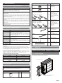 3
3
-
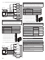 4
4
-
 5
5
-
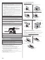 6
6
-
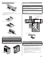 7
7
-
 8
8
-
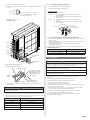 9
9
-
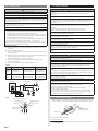 10
10
-
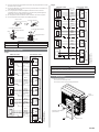 11
11
-
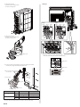 12
12
-
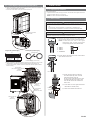 13
13
-
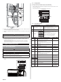 14
14
-
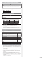 15
15
-
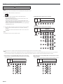 16
16
-
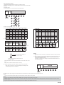 17
17
-
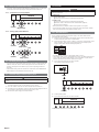 18
18
-
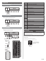 19
19
-
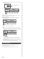 20
20


Fujitsu AOTG45LBLA6 Guide d'installation
- Taper
- Guide d'installation
- Ce manuel convient également à
dans d''autres langues
Documents connexes
-
Fujitsu ROMH36AFXZJ Guide d'installation
-
-
-
-
-
-
Fujitsu AOU36RLXFZH Guide d'installation
-
Fujitsu ASU9RLF1 Guide d'installation
-
Fujitsu AOYA72LALT Guide d'installation
-
Fujitsu AUGA36FRTA Guide d'installation
Autres documents
-
Whirlpool PACW212CO Le manuel du propriétaire
-
-
LG ABUW36GM2S1.ENWTMEA Guide d'installation
-
Mitsubishi Mr.Slim PKA-A.HA4 Guide d'installation
-
-
Haier AC60FS1ERA Manuel utilisateur
-
Mitsubishi Electric PUMY-P125 Guide d'installation
-
Haier 1U24AP2VHA Manuel utilisateur
-
-
 Mitsubishi Electronics USA MXZ-8C60NA-U1 Guide d'installation
