

2 | Amplified Loudspeaker Controller Install and User Guide
Important Safety Instructions
CAUTION
RISK OF ELECTRIC
SHOCK DO NOT OPEN
This unit has been engineered and manufactured to ensure your
personal safety. But IMPROPER USE CAN RESULT IN POTENTIAL
ELECTRICAL SHOCK OR FIRE HAZARD.
In order not to defeat the safeguards incorporated into this
product, observe the following basic rules for its installation, use
and service. Please read these “Important Safeguards” carefully
before use.
• Read these instructions.
• Keep these instructions.
• Heed all warnings.
• Follow all instructions.
• Do not use this equipment near water.
• Clean only with a dry cloth.
• Do not block any ventilation openings. Install in accordance
with the manufacturer’s instructions.
• Do not install near any heat sources such as radiators, heat
registers, stoves, or other apparatus that produce heat.
• Do not defeat the safety purpose of the polarized or
grounding-type plug. A polarized plug has two blades with one
wider than the other. A grounding-type plug has two blades
and a third grounding prong. The wide blade or the third prong
are provided for your safety. If the provided plug does not fit
into your outlet, consult an electrician for replacement of the
obsolete outlet.
• Protect the power cord from being walked on or pinched
particularly at plugs, convenience receptacles, and the point
where they exit from the apparatus.
• Only use attachments/accessories specified by the
manufacturer.
• Use only with the rack, cart, stand, tripod, bracket, or
table specified by the manufacturer, or sold with the
apparatus. When a cart is used, use caution when
moving the cart/apparatus combination to avoid
injury from tip-over.
• Unplug this apparatus during lightning storms or when
unused for long periods of time.
• Refer all servicing to qualified service personnel. Servicing is
required when the apparatus has been damaged in any way,
such as power-supply cord or plug is damaged, liquid has
been spilled or objects have fallen into the apparatus, the
apparatus has been exposed to rain or moisture, does not
operate normally, or has been dropped.
• The apparatus shall be connected to a MAINS socket outlet
with a protective earth grounding connection
• Where the MAINS plug or an appropriate coupler is used as the
disconnect device, the disconnect device shall remain readily
operable.
CLASS3
WIRING
THE TRIANGLE WITH THE LIGHTNING BOLT IS USED TO ALERT THE USER TO
THE RISK OF ELECTRIC SHOCK.
CLASS3
WIRING
THE TRIANGLE WITH THE EXCLAMATION POINT IS USED TO ALERT THE
USER TO IMPORTANT OPERATING OR MAINTENANCE INSTRUCTIONS.
THE CE-MARK INDICATES THE COMPLIANCE WITH THE LOW VOLTAGE AND
ELECTROMAGNETIC COMPATIBILITY.
SYMBOL FOR EARTH/GROUND CONNECTION.
SYMBOL INDICATING THAT THE EQUIPMENT IS FOR INDOOR USE ONLY.
SYMBOL FOR CONFORMITY WITH DIRECTIVE 2012/19/EC OF THE
EUROPEAN PARLIAMENT ON WASTE ELECTRICAL AND ELECTRONIC
EQUIPMENT (WEEE).
DO NOT USE THE UNIT AT ALTITUDES ABOVE 2000 M.
DO NOT USE THE UNIT IN TROPICAL ENVIRONMENT.
CLASS3
WIRING
WARNING: TO REDUCE THE RISK OF ELECTRIC SHOCK, DO NOT ATTEMPT
TO OPEN ANY PART OF THE UNIT. NO USER-SERVICEABLE PARTS INSIDE.
REFER SERVICING TO QUALIFIED SERVICE PERSONNEL.
CLASS3
WIRING
CONNECTION TO THE MAINS SHALL BE DONE ONLY BY A ELECTRO-
TECHNICAL SKILLED PERSON ACCORDING THE NATIONAL REQUIREMENTS
OF THE COUNTRIES WHERE THE UNIT IS SOLD.
CLASS3
WIRING
DO NOT USE THIS ALC IF THE ELECTRICAL POWER CORD IS FRAYED OR
BROKEN.
CLASS3
WIRING
TO AVOID ELECTRICAL SHOCK, DO NOT TOUCH ANY EXPOSED SPEAKER
WIRING WHILE THE ALC IS OPERATING.
CLASS3
WIRING
DO NOT SPILL WATER OR OTHER LIQUIDS INTO OR ON THE ALC.
CLASS3
WIRING
NO NAKED FLAME SOURCES SUCH AS LIGHTED CANDLES SHOULD BE
PLACED ON THE ALC.
CLASS3
WIRING
WARNING TO PREVENT INJURY, THIS APPARATUS MUST BE SECURELY
ATTACHED TO THE FLOOR/WALL IN ACCORDANCE WITH THE INSTALLATION
INSTRUCTIONS.
CLASS3
WIRING
THIS DEVICE MUST BE POWERED EXCLUSIVELY BY EARTH CONNECTED
MAINS SOCKETS IN ELECTRICAL NETWORKS COMPLIANT TO THE IEC 364
OR SIMILAR RULES
CLASS3
WIRING
DISCONNECT THE AC MAINS SOURCE BEFORE ATTEMPTING TO CLEAN ANY
PART OF THE ALC
CLASS3
WIRING
COMMUNITY SUGGESTS PLUGGING THE ALC-3202D TO A 16 A RATING, C OR
D CURVE, 10 KA SECTIONING BREAKER.
CLASS3
WIRING
IT IS HIGHLY RECOMMENDED TO UNPLUG THE OUTPUT CONNECTORS
BEFORE PROCEEDING WITH THE SELF CHECK PROCEDURE
CLASS3
WIRING
THE TESTING SIGNALS MIGHT CAUSE LOUDSPEAKER IMPAIRMENTS.
CLASS3
WIRING
OUTPUT TERMINALS ARE HAZARDOUS: WIRING CONNECTION TO THESE
TERMINALS REQUIRES INSTALLATION BY AN INSTRUCTED PERSON AND
THE USE OF READY MADE LEADS.
CLASS3
WIRING
PROPERLY FIT THE AC MAINS PLUG TO THE ALC INLET.
BEFORE POWERING THIS ALC, VERIFY THAT THE CORRECT VOLTAGE RATING
IS BEING USED.
CLASS3
WIRING
VERIFY THAT YOUR MAINS CONNECTION IS CAPABLE OF SATISFYING THE
POWER RATINGS OF THE DEVICE.
CLASS3
WIRING
TAKE CARE TO LOCK THE OUTPUT TERMINAL BEFORE SWITCHING THE
DEVICE ON.
IMPORTANT: The manufacturer cannot be held responsible
for damages caused to persons, things or data due to an
improper or missing ground connection.
Contact the authorized service center for ordinary and
extraordinary maintenance.
It is absolutely necessary to verify these fundamental
requirements of safety and, in case of doubt, require an
accurate check by qualified personnel.
Note: Every eort has been made to ensure that the
information contained in this manual was complete and
accurate at the time of printing. However, due to ongoing
technical advances, changes or modifications may have
occurred that are not covered in this manual. The latest
version is available at communitypro.com.
EN

Amplified Loudspeaker Controller Install and User Guide | 3
EC Declaration of Conformity
Community Professional Loudspeakers
333 East Fifth Street
Chester, PA 19013
USA
We declare that under our sole responsibility the products:
Model Names:
ALC-404D
AL C-16 04D
ALC-3202D
Intended use: Professional Audio Amplifier
Are in conformity with the provisions of the following EC
Directives, including all amendments, and with national
legislation implementing these directives:
2014/35/EU Low Voltage Directive
2014/30/EU Electromagnetic Compatibility Directive
2011/65/EU RoHs Directive
The following harmonized standards apply:
EN 60065:2014 /AC:2016
EN 55032:2012
EN 55035:2017
EN 55103-2:2009 /IS:2012
EN 61000-3-3:2013
EN 61000-3-2:2014
Complies with:
CAN/CSA 60065:16
UL Standard No. 60065-2015
WEEE Directive
This symbol indicates that when the end user wishes
to discard this product, it must be sent to separate
collection facilities for recovery and recycling. By
separating this product from other household-type
waste, the volume of waste sent to incinerators or
landfills will be reduced and natural resources will
thus be conserved.
The Waste Electrical and Electronic Equipment Directive (WEEE
Directive) aims to minimize the impact of electrical and electronic
goods on the environment.
All of our products are marked with the WEEE symbol; this
indicates that this product must NOT be disposed of with other
waste.
For more information about where you can send your waste
equipment for recycling, please contact your local distributor.
Packing List
The box contains the following:
1x ALC-3202D (with Phoenix connectors plugged in)
1x Phoenix MC 1,5/4-ST-3,81 - 1803594 plug
3x Phoenix MC 1,5/6-ST-3,81 - 5447900 plug
1x Phoenix PC 5/4-STF1-7,62 - 177859 plug
3x IEC power cord
1x User guide
OR
1x ALC-404D or ALC-1604D (with Phoenix connectors plugged in)
1x Phoenix MC 1,5/4-ST-3,81 - 1803594 plug
3x Phoenix MC 1,5/12-ST-3,81 - 1803675 plug
1x Phoenix PC 5/8-STF1-7,62 - 177891 plug
3x IEC power cord
1x User guide
In an eort to reduce the quantity of printed material while
enhancing the quality of content, we have decided to adopt a new
approach for the production of this quick guide.
Vital information has been condensed in two pages, and all
illustrations and tables follow. Each section's color bar (ex.
)
refers to the outlined area on front or rear panel of the ALC image
and the corresponding information tables. Call-out bubbles
1
/
A
guide you to specific elements of those sections.
Please take time to read and understand all warnings and safety
instructions on the previous page of this manual.
ArmoníaPlus is a trademarked control software product from
Powersoft S.p.A.
EN

4 | Amplified Loudspeaker Controller Install and User Guide
Consignes de sécurité importantes
ATTENTION
RISQUE DE CHOC
ÉLECTRIQUE NE
PAS OUVRIR
CLASS3
WIRING
LE TRIANGLE AVEC LE SYMBOLE D'UN ÉCLAIR EST UTILISÉ POUR ALERTER
L'UTILISATEUR DU RISQUE DE CHOC ÉLECTRIQUE.
CLASS3
WIRING
LE TRIANGLE AVEC LE POINT D'EXCLAMATION EST UTILISÉ POUR ALERTER
L'UTILISATEUR SUR DES INSTRUCTIONS DE FONCTIONNEMENT OU
D'ENTRETIEN IMPORTANTES.
LA MARQUE CE INDIQUE LA CONFORMITÉ AVEC LA BASSE TENSION ET LA
COMPATIBILITÉ ÉLECTROMAGNÉTIQUE.
SYMBOLE POUR LA CONNEXION TERRE / MASSE.
SYMBOLE INDIQUANT QUE L'ÉQUIPEMENT EST DESTINÉ À UN USAGE
INTÉRIEUR UNIQUEMENT.
SYMBOLE DE CONFORMITÉ AVEC L A DIRECTIVE 2012/19/CE DU PARLEMENT
EUROPÉEN RELATIVE AUX DÉCHETS D'ÉQUIPEMENTS ÉLECTRIQUES ET
ÉLECTRONIQUES (DEEE).
NE PAS UTILISER PAS L'APPAREIL À DES ALTITUDES AU-DESSUS DE 2000
M.
NE PAS UTILISER L'APPAREIL DANS UN ENVIRONNEMENT TROPICAL.
CLASS3
WIRING
AVERTISSEMENT : POUR RÉDUIRE LE RISQUE DE CHOC ÉLECTRIQUE, NE PAS
ESSAYER D'OUVRIR TOUTE PARTIE DE L'APPAREIL. AUCUNE PIÈCE RÉPARABLE
PAR L'UTILISATEUR A L'INTÉRIEUR. RENVOYER L'ENTRETIEN AU PERSONNEL DE
SERVICE QUALIFIÉ.
CLASS3
WIRING
LE BRANCHEMENT AU SECTEUR NE SERA EFFECTUE QUE PAR UNE
PERSONNE QUALIFIÉE DANS LE DOMAINE ÉLECTRO-TECHNIQUE SELON
LES EXIGENCES NATIONALES DES PAYS OU L'APPAREIL EST VENDU.
CLASS3
WIRING
N'UTILISER PAS CET AMPLIFICATEUR SI LE CORDON D'ALIMENTATION
ÉLECTRIQUE EST EFFILOCHÉ OU BRISÉ.
CLASS3
WIRING
POUR ÉVITER LES CHOCS ÉLECTRIQUES, NE TOUCHER AUCUN CÂBLAGE
D'ENCEINTE EXPOSÉ LORSQUE L'AMPLIFICATEUR FONCTIONNE.
CLASS3
WIRING
NE PAS RENVERSER D'EAU OU D'AUTRES LIQUIDES DANS OU SUR
L'AMPLIFICATEUR.
CLASS3
WIRING
AUCUNE SOURCE DE FLAMME NUE COMME DES BOUGIES ALLUMÉES NE
DOIT ÊTRE PLACÉE SUR L'AMPLIFICATEUR.
CLASS3
WIRING
AVERTISSEMENT POUR PRÉVENIR LES BLESSURES, CET APPAREIL
DOIT ÊTRE SOLIDEMENT FIXÉ AU SOL / MUR EN CONFORMITÉ AVEC LES
INSTRUCTIONS D'INSTALLATION.
CLASS3
WIRING
CET APPAREIL DOIT ÊTRE ALIMENTÉ EXCLUSIVEMENT PAR
RACCORDS DE SECTEUR CONNECTÉS À LA TERRE DANS DES RÉSEAUX
ÉLECTRIQUES CONFORMES AUX NORMES CEI 364 OU AUX RÈGLES SIMILAIRES
CLASS3
WIRING
DÉCONNECTER LA SOURCE SECTEUR AV AVANT DE TENTER TOUT
NETTOYAGE DE L' ALC
CLASS3
WIRING
COMMUNITY SUGGÈRE DE CONNECTER LE ALC-3202D À UN DISJONCTEUR DE
SECTIONNEMENT DE 16 A, COURBE C OU D,, À UN DISJONCTEUR DE 10 KA.
CLASS3
WIRING
IL EST FORTEMENT RECOMMANDÉ DE DÉBRANCHER LES CONNECTEURS
DE SORTIE AVANT DE PROCÉDER À LA PROCÉDURE D'AUTO-VÉRIFICATION
CLASS3
WIRING
LES SIGNAUX D'ESSAI PEUVENT CAUSER DES DÉFAILLANCES AUX
HAUT-PARLEURS.
CLASS3
WIRING
LES TERMINAUX DE SORTIE SONT DANGEREUX : LA CONNEXION DU
CÂBLAGE À CES BORNES REQUIERT L'INSTALLATION PAR UNE PERSONNE
FORMÉE ET L'UTILISATION DE FILS PRÊTS À L'EMPLOI.
CLASS3
WIRING
BRANCHER CORRECTEMENT LA FICHE SECTEUR CA À L'ENTRÉE DE
L'AMPLIFICATEUR.
AVANT D'ALIMENTER CET ALC, VÉRIFIER QUE LA TENSION UTILISÉE EST
CORRECTE.
CLASS3
WIRING
VÉRIFIER QUE VOTRE CONNEXION SECTEUR EST CAPABLE DE SATISFAIRE
LES VALEURS DE PUISSANCE DE L'APPAREIL.
CLASS3
WIRING
VEILLER À VERROUILLER LA BORNE DE SORTIE AVANT D'ALLUMER
L'APPAREIL.
Le fabricant ne peut être tenu responsable des dommages causés
aux personnes, aux choses ou aux données en raison d'une
connexion à la terre incorrecte ou manquante.
Contacter le centre de service autorise pour un entretien ordinaire
et extraordinaire.
Il est absolument nécessaire de vérifier ces conditions
fondamentales de sécurité et, en cas de doute, d'obtenir une
vérification précise par du personnel qualifié.
FR
Cet appareil a été conçu et fabriqué pour assurer votre sécurité
personnelle. Mais UNE UTILISATION INCORRECTE PEUT ENTRAÎNER
UN RISQUE D'ÉLECTROCUTION OU D'INCENDIE.
Respecter les règles de base suivantes pour son installation,
utilisation et entretien, afin de ne pas compromettre les mesures
de sécurité incorporées dans ce produit. Veuillez lire attentivement
ces "Consignes de sécurité importantes" avant utilisation.
• Lire ces instructions.
• Conserver ces instructions.
• Tenir compte de tous les avertissements.
• Suivre toutes les instructions.
• Ne pas utiliser cet équipement près de l'eau.
• Nettoyer uniquement à l'aide d'un chion sec.
• Ne bloquer aucune bouche d'aération. Installer
conformément aux instructions du fabricant.
• Ne pas installer à proximité de sources de chaleur telles que
radiateurs, bouches de chaleur, poêles ou autres appareils
produisant de la chaleur.
• Ne pas déjouer l'objectif de sécurité de la fiche polarisée
ou mise à la terre. Une fiche polarisée possède deux lames
dont l'une est plus large que l'autre. Une prise de terre a
deux lames et une troisième broche de mise à la terre. La
lame large ou la troisième broche sont fournies pour votre
sécurité. Si la fiche fournie ne rentre pas dans votre prise,
consulter un électricien pour le remplacement de la prise
obsolète.
• Protéger le cordon d'alimentation contre tout piétinement ou
pincement, en particulier au niveau des fiches, des prises de
courant et du point de sortie de l'appareil.
• Utiliser uniquement les fixations/accessoires spécifiés par le
fabricant.
• Utiliser uniquement avec le chariot, le support, le
trépied, l'étrier ou la table spécifiée par le fabricant
ou vendus avec l'appareil. Lorsqu'un chariot est
utilisé, faire attention pendant le déplacement du
bloc chariot/appareil pour éviter les blessures
causées par un renversement.
• Débrancher cet appareil pendant les orages ou lorsqu'il n'est
pas utilisé pendant de longues périodes.
• Confier toute réparation à un technicien qualifié. Un entretien
est requis lorsque l'appareil a été endommagé de quelque
façon que ce soit, par exemple un cordon d'alimentation ou
une prise endommagée, du liquide qui a été renversé ou des
objets qui sont tombés dans l'appareil, si l'appareil a été
exposé à la pluie ou à l'humidité ou s'il est tombé.
• L'appareil doit être connecté à une prise SECTEUR dotée
d'une mise à la terre de protection
• Lorsque la prise SECTEUR ou un coupleur approprié est
utilisé comme dispositif de déconnexion, le dispositif de
déconnexion doit rester facilement accessible.

Amplified Loudspeaker Controller Install and User Guide | 5
FR
Directive DEEE
Ce symbole indique que lorsque l'utilisateur final
souhaite se débarrasser de ce produit, il doit
l'envoyer à des sociétés de collecte distinctes pour
sa récupération et recyclage. En séparant ce produit
des autres déchets ménagers, le volume de déchets
envoyés aux incinérateurs ou aux décharges sera
réduit et les ressources naturelles seront ainsi
conservées.
La directive relative aux déchets d'équipements électriques
et électroniques (directive DEEE) vise à minimiser l'impact des
produits électriques et électroniques sur l'environnement.
Tous nos produits sont marqués du symbole DEEE ; ceci indique
que ce produit NE doit PAS être éliminé avec d'autres déchets.
Pour plus d'informations sur l'endroit où vous pouvez envoyer
vos équipements usagés pour le recyclage, veuillez contacter
votre distributeur local.
Déclaration de Conformité CE
Community Professional Loudspeakers
333 East Fifth Street
Chester, PA 19013
USA
Nous déclarons sous notre seule responsabilité que les produits
:
Nom des modèles :
ALC-404D
AL C-16 04D
ALC-3202D
Utilisation prévue : Amplificateur audio professionnel
Sont conformes aux dispositions des directives CE suivantes,
y compris toutes les modifications, et à la législation nationale
mettant en œuvre ces directives :
Directive basse tension 2014/35 / UE
Directive sur la compatibilité électromagnétique 2014/30 / EU
Directive RoHs 2011/65/EU
Les normes harmonisées suivantes sont appliquées :
EN 60065 : 2014 /AC:2016
EN 55032 : 2012
EN 55035 : 2017
EN 55103-2 : 2009 /IS:2012
EN 61000-3-3 : 2013
EN 61000-3-2 : 2014
Conforme à:
CAN / CSA 60065: 16
Norme UL n ° 60065-2015
Afin de réduire la quantité de documents imprimés tout en
améliorant la qualité du contenu, nous avons décidé d’adopter une
nouvelle approche pour la production de ce guide rapide.
Les informations vitales ont été condensées en deux pages et
toutes les illustrations et les tableaux suivent. La barre de couleur
de chaque section (ex.
) fait référence à la zone délimitée
sur le panneau avant ou arrière de l'image ALC et aux tableaux
d'informations correspondants. Des bulles de rappel
1
/
A
vous
guident vers des éléments spécifiques de ces sections.
Veuillez prendre le temps de lire et de comprendre tous les
avertissements et consignes de sécurité de la page précédente de
ce manuel.
ArmoníaPlus est un produit logiciel de marque déposée Powersoft
S.p.A.

6 | Amplified Loudspeaker Controller Install and User Guide
Connections
Signal Grounding
There is no ground switch or terminal on the ALCs. The unit’s
signal grounding system is automatic. In order to limit hum and/
or interference entering the signal path, use balanced input
connections.
In the interests of safety, the unit MUST always operate with
electrical safety earth connected to the chassis via the dedicated
Protective Earth
wire.
Analog Audio Input Connections
Analog input connections are made via the Phoenix MC
1,5/6-ST-3,81 5447900 connector on the ALC-3202D (or via the
Phoenix MC 1,5/12-ST-3,81 1803675 connector on the ALC-404D or
AL C-16 04D).
Remote Level Adjustment
The level of each channel can be remotely adjusted by means
of a linear 10 kΩ potentiometer connected to the input LEVEL
connector.
When the CH1 MSTR switch is in the OFF position the remote level
potentiometers work independently on each separate channel.
When the CH1 MSTR switch is in the ON position the remote level
potentiometer of channel 1 acts as a master level, controlling the
volume of all channels.
The remote level controls are in series with the level adjustment
knobs in the front panel.
Breaker Save
This feature may be activated when the power grid is unable to
provide enough current to continuously drive the loads, or when
the number of ALCs connected to the same outlet is such that one
can reach the critical power absorption of the line.
When activated, the Breaker Save halves the maximum continuous
current absorption from the mains. This slightly reflects on the
overall performance of the system, reducing the available output
power.
In order to activate the Breaker Save feature, locate the BRK SAVE
switch on the rear panel.
Remote On/O
Remote ON/OFF is available through the dedicated terminals on
the rear panel.
Both terminals respond to the dierential voltage between the
contacts: a voltage dierence in the range 5 V
DC
- 24 V
DC
triggers
the control. Any voltage exceeding 28 V
DC
may damage the input
circuitry.
The couple of terminals act depending on the actual state of the
ALC, in accordance with the following table.
REMOTE ON REMOTE OFF ALC STATE
Vdi ≥ 5V Any Force Turn ON
Vdi < 3V Vdi ≥ 5V Force Turn OFF
Vdi < 3V Vdi < 3V
No Change
(Keep either standby or in current state)
Gain selection
ALCs can operate with dierent gain applied to the input signal.
This feature is designed to match the voltage of the input signal.
A proper combination of the position of two GAIN switches on the
rear panel sets the operating gain of the amplifier
Preliminary operations
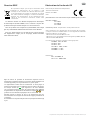
Location
Install your Community Amplified Loudspeaker Controller (ALC) in
well ventilated rack cabinets.
Secure both front and rear brackets to the rack.
Connect the AC Mains connector to a circuit breaker.
Install the ALC far from EMF emitting devices.
Avoid placing the ALC close to heat generating sources.
Cooling
The ventilation openings must not be impeded by any item, keep
a distance of at least 19.7 in. (50 cm) from the front and rear
ventilation openings of the ALC.
Community ALCs implement a forced-air cooling system to
maintain constant operating temperatures. Air enters from the
front panel, exiting at the back of the unit.
The cooling system features variable-speed DC fans controlled
by the heat sink mounted sensors. This ensures that fan noise and
internal dust accumulation are kept to a minimum.
In the rare event of overheating, sensing circuits shut down all
channels until the ALC cools down to a safe operating temperature.
Normal operation is resumed automatically without the need for
user intervention.
ALCs can be stacked one on top of the other, leave one rack unit
empty every four to guarantee adequate air flow.
Cleaning
Use a dry cloth for cleaning the chassis and the front panel. Air
filter cleaning should be scheduled in accordance with the dust
levels in the ALC’s operating environment.
In order to clean the vent filters remove the front cover by firmly
gripping the outermost black panels and pull them outwards
Use compressed air to remove the dust from filters, or wash them
with clean water (let the filter dry thoroughly before reinstalling
them).
AC Mains Supply
ALCs implement an universal switching mode power supply with
power factor correction operating in the range from 100 VAC up to
240 VAC ±10%.
AC mains connection is in the rear panel through the IEC C20 inlet,
the approved power cord is provided.
Switching the ALC On and O
Once properly powered (power cord inserted, sectioning breaker
closed), the system can be either ON or in STANDBY mode
depending on its state at latest power o.
In order to toggle the ALC between ON and STANDBY press and
hold the power button for 3 seconds. Please consider that the
operating condition can be modified by the REMOTE ON and
REMOTE OFF configuration.
Energy Save
The Smart Rails Management technology implemented in the
power supply unit allows to reduce the power consumption when
the input signal falls under a defined threshold.
When On, Energy Save is active on each channel independently.
If the signal is missing for more than 30 minutes on all channels,
the auto standby is applied and the main PSU is turned o to
further save energy (Time out time is selectable via ArmoníaPlus).
Normal operation is resumed in a matter of milliseconds when an
incoming signal is detected.
In order to activate the Energy Save feature, operate the NRG
SAVE dip switch on the rear panel.

Amplified Loudspeaker Controller Install and User Guide | 7
Digital Audio Input Connection
All ALCs accept two/four input streams from the Dante
®
connection
through the Dante
®
port. Cabling must comply to TIA/EIA-568-B
and adopt the T568B scheme pinout.
In order to implement a Dante® network, a computer running
Dante® Controller have to be used. Dante® Controller is a
software application that manages devices on the network. ALCs
are automatically discovered and displayed in Dante® Controller
with the default identifier:
MODELNAME-SERIAL
(e.g.ALC-3202D-71520).
Ethernet Connection
The port labeled Ethernet is designed to remotely control the
ALC via an Ethernet connection through a personal computer and
Powersoft ArmoníaPlus System Manager software.
Powersoft recommends the use of Ethernet Cat5 straight through
patch cables with pin/pair assignments TIA/EIA-568-B, i.e. T568B.
Output Connections
Output connections are made via the Phoenix PC 5/4-STF1-7,62
177859 port (or PC 5/8-STF1-7,62 177891 port ALC-404D/1604D).
Any mixed configuration of low and high impedance output loads
can be made: in order to set the load configuration, each channel
is provided with four DIP switches.
Hi-Z 70V/100V Operations
Any channel can drive 70V/100V (Hi-Z) distributed line
loudspeakers. To connect any channel’s output to a 70V/100V line,
set the rear panel DIP switch corresponding to the channel.
When using Community ALC's with factory-authored loudspeaker
presets, it is not necessary to use the built-in HPF (High Pass
Filter) DIP switches on the rear of the amplifier. While these
switches can select a HPF of 35Hz or 70Hz, each Community 70V
/ 100V loudspeaker preset already includes a HPF appropriate for
the selected loudspeaker model.
Low-Z 2Ω Load Operation
The 2Ω switch allows activation of all output channels set to
match the low impedance operating condition (i.e. in Low-Z
configuration) optimizing the performance with very low loads,
by limiting the maximum output voltage to 85 Vpeak per channel.
When using ALC's with Community-authored loudspeaker
presets this switch becomes redundant and can be ignored. Each
loudspeaker preset already includes limiters preset to values that
will limit voltages to safe operating levels.
If using an ALC without a Community-authored loudspeaker
preset, use this switch as intended for 2Ω loads. Never connect
loads lower than 2Ω to any output channel on any ALC under any
circumstances.
Diagnostics - GPO - Alarms
ALCs provide a pair of paralleled general purpose output
connections per channel: one Normally Open NO and one
Normally Closed
NC.
The connections are available on the back panel via the 6-pin
(ALC-3202D) or 12-pin (ALC-404D/1604D) Phoenix connectors.
When the amplifier is in normal operating condition the NO contacts
are closed, while the NC contacts are open, and vice-versa.
These contacts are used to report potentially dangerous faults or
generally unsafe operation conditions by toggling alarm switches
relative to the following events, and any fault preventing the
normal operation of an output channel:
No AC mains (i.e. system shutdown)
Thermal stress (the system temperature is too high and the
thermal protection is engaged)
Short circuit in output wiring (either the loudspeaker or the line
is in short)
ALC is in Standby
All ALCs feature further monitoring on pilot tone and output load
through ArmoníaPlus System Manager.
Self Check
The self check procedure tests the ALC status and reports the
user in case of failures.
After few minutes, at the end of the self check procedure, a
combination of lit LED in the LED panel provides information about
the amplifier status.
In order to exit the self check test and resume normal operations,
press the self check push button once
6
.
If self check cannot be started because of a fault, the check LED
will blink fast, while a reassuring slow blink is an indication of a
completed self check procedure.
Pilot Tone Monitoring
The detection of a mismatch in the input pilot tone parameters
(frequency and voltage level) can be used to trigger the backup policy
and activate an alert through the general purpose output switch.
The output pilot tone detection relies on an external signal passing
through the ALC or the internal post DSP pilot tone generator; in
both cases any mismatch between the detected signal and the set
thresholds triggers the general purpose output switches.
Networking
ALCs support star network topology via the Ethernet port and
Dante® networking via the Dante® port.
IP Addressing
Factory default network settings are DHCP/AutoIP.
In order for the ALC to self-configure when connected to an
existing LAN or PC. Fixed IP policy can also be adopted and
configured through ArmoníaPlus System Manager.
If a DHCP server is not active within the network, the ALC platform
initiates a stateless address auto-configuration (i.e. Zero-
configuration networking methodology). It self-assigns a local
numeric network address (of the type 169.254.x.y – 172.31.*.*
for the secondary network if present – with a subnet mask
255.255.0.0) and automatically distributes and resolves the host
names of the networking devices.
Both ArmoníaPlus and the ALC must belong to the same subnet. If
a DHCP server is present on the network and an ALC is in AUTO IP,
networking may become unstable.
IMPORTANT: As a rule of thumb, turn the DHCP server ON before
connecting the ALCs.
IP addressing of an ALC is established during the bootstrap: when
the amplifier discovers a DHCP server on the network during the
startup, it negotiates the networking parameters. If the ALC does
not reveal a DHCP server on the network during the startup, it sets
itself in AUTO IP mode.
ArmoníaPlus System Manager
ArmoníaPlus System Manager is the configuring interface
that allows system setting and customization of the ALCs.
ArmoníaPlus can be installed on a PC running Windows (7 and
higher). Download ArmoníaPlus System Manager for free from
the website: http://www.communitypro.com/armoniaplus
Input Selection and Backup Policy
it is possible to select among two input signal sources per channel:
analog and Dante® streams. ArmoníaPlus System Manager
software provides an interface to select the input source.
Furthermore ALCs implement a backup policy aimed to improve
reliability against signal fault. By assigning a bus priority to the
two dierent input sources per channel, the system is able to
automatically switch to a reliable input connection in case of
signal drop or pilot tone mismatch.
Output Load Monitoring
Through the ArmoníaPlus System Manager software it is possible
to set the thresholds on the load impedance, at given frequency,
that trigger the general purpose output of any channel in ALCs.

8 | Amplified Loudspeaker Controller Install and User Guide
Location
Cooling
1 1
1 RU
1 RU
1 RU
1 1
2 2
2 2
3 3
3 3
4 4
4 4
5
AMPLIFIED LOUDSPEAKER CONTROLLER
ALC-404D
AMPLIFIED LOUDSPEAKER CONTROLLER
ALC-404D
AMPLIFIED LOUDSPEAKER CONTROLLER
ALC-404D
AMPLIFIED LOUDSPEAKER CONTROLLER
ALC-404D
AMPLIFIED LOUDSPEAKER CONTROLLER
ALC-404D
AMPLIFIED LOUDSPEAKER CONTROLLER
ALC-404D
AMPLIFIED LOUDSPEAKER CONTROLLER
ALC-404D
AMPLIFIED LOUDSPEAKER CONTROLLER
ALC-404D
AMPLIFIED LOUDSPEAKER CONTROLLER
ALC-404D

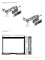
Amplified Loudspeaker Controller Install and User Guide | 9
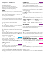
Exposing the Control Panel
Dimensions
Duecanali
1604
19.0 in
442 mm
14.7 in
373 mm
14.0 in
357 mm
14.4 in
365.5 mm
ALC-3202D
(2 Channel)
ALC-404D
ALC-1604D
(4 Channel)

10 | Amplified Loudspeaker Controller Install and User Guide
Single Ended
(Flipped view)
(Flipped view)
Bridged
Ch 1
Ch 2
Low-Z High-Z 100V 70V HPF @ 35 Hz HPF @ 70 Hz
A
B
C
D
E
F
G
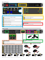
Front Panel
Rear Panel
LED Panel
8
Channel Status LED meters
9
System Status LEDs
Output section
10
Output connector
11
Output configuration Dip Switches
Serial Port
Reserved for service operations.
ground
mains
AC Mains Connector
IEC C19
Control Panel
1
Operating Mode LEDs (ON/STANDBY)
2
Power pushbutton
3
ArmoníaPlus Callback pushbutton
4
Soft Reset pushbutton
5
Hard Reset pushbutton
6
Self Check pushbutton
7
CH1, CH2 attenuators (+ CH3, CH4 - ALC-404D, ALC-1604D)
(Flipped view)
Bridged
Single Ended
(Flipped view)
Ch 1
Ch 3
Ch 2
Ch 4
ALC-3202D AL C-40 4D or A LC-160 4D
70V
lo-Z
35Hz
HPF Off
100V
hi-Z
70Hz
HPF On
1 2 3 4 5 6 7 8
A
70V
lo-Z
35Hz
HPF Off
100V
hi-Z
70Hz
HPF On
1 2 3 4 5 6 7 8
F
70V
lo-Z
35Hz
HPF Off
100V
hi-Z
70Hz
HPF On
1 2 3 4 5 6 7 8
D
70V
lo-Z
35Hz
HPF Off
100V
hi-Z
70Hz
HPF On
1 2 3 4 5 6 7 8
B
70V
lo-Z
35Hz
HPF Off
100V
hi-Z
70Hz
HPF On
1 2 3 4 5 6 7 8
G
70V
lo-Z
35Hz
HPF Off
100V
hi-Z
70Hz
HPF On
1 2 3 4 5 6 7 8
E
70V
lo-Z
35Hz
HPF Off
100V
hi-Z
70Hz
HPF On
1 2 3 4 5 6 7 8
C
10
11
9
8
1
2
63
7
4 5
10

Amplified Loudspeaker Controller Install and User Guide | 11
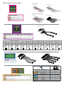
Rear Panel (continued)
Input Gain Selection
26 dB 29 dB 32 dB 35 dB CH1 Master BRK Save NRG Save USR A USR B 2 Ω*
2-3 2-3 2-3 2-3 1 4 5 6 7 8
26 dB
1 2 3 4 5 6 7 8
23
29 dB
1 2 3 4 5 6 7 8
23
32 dB
1 2 3 4 5 6 7 8
23
35 dB
1 2 3 4 5 6 7 8
23
CH1 MASTER
1
1 2 3 4 5 6 7 8
BRK SAVE
4
1 2 3 4 5 6 7 8
NRG SAVE
5
1 2 3 4 5 6 7 8
USR A
6
1 2 3 4 5 6 7 8
7
1 2 3 4 5 6 7 8
USR B
8
1 2 3 4 5 6 7 8
2 Ω
* ALC-404D and ALC-1604D models only. (ALC3202 does not have 2 Ω opertion).
Remote On/O
Ch 2
Ch 1
common
Alarm
GPO/Alarm connector
1 2 3 4 5 6 7 8
Color code (TIA/EIA-568-B) Pin
ORANGE / WHITE 1
ORANGE 2
GREEN / WHITE 3
BLUE 4
BLUE / WHITE 5
GREEN 6
BROWN / WHITE 7
BROWN 8
RJ45
Ethernet and Dante
®
ports
16
Ethernet port (RJ45)
17
Dante
®
port (RJ45)
Input section
12
Remote Level connector
13
Line Input connector
Remote On/O-Configuration dip switches
14
Remote On/O connector (Phoenix MC 1,5/4-ST-3,81 1803594)
15
System Configuration dip switches
ALC-3202D
ALC-3202D
AL C-40 4D or A LC-160 4D
AL C-40 4D or A LC-160 4D
common
common
common
common
Ch 4
Ch 3
Ch 2
Ch 1
Ch 2
Ch 1
Input
Remote Level
Ch 1
(or Master)
Ch 2
Input
Ch 4
Ch 3
Ch 2
Remote Level
Ch 1
(or Master)
Ch 4
Ch 3
Ch 2
Ch 1
common
14
15
12
13
16 17

12 | Amplified Loudspeaker Controller Install and User Guide
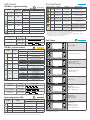
LED Charts
Label Label Type Action Description
2
POWER Pushbutton
keep pressed for
3 seconds
Toggle system ready /
standby mode
3
CALL Pushbutton press
Highlight the ALC in the
ArmoníaPlus workspace
4
SOFT
RESET
1
Pushbutton
keep pressed for
3 seconds
Reset network parameters
to factory default
5
HARD
RESET
1
Pushbutton
keep pressed for
3 seconds
Reboot the system
6
CHECK Pushbutton
keep pressed for
3 seconds
Start the self-checking
procedure
3
7
CH1
2
Potentiometer
turn
counter-clockwise
Attenuate the output level
of the signal on channel 1
CH2
2
Potentiometer
turn
counter-clockwise
Attenuate the output level
of the signal on channel 2
The push-buttons are disabled when connected to Armonía.
1. Keep pressed both the SOFT RESET button and the HARD RESET button for at least 3 seconds
to completely reset the ALC to its factory default configuration (any preset stored in the
internal memory will be lost and replaced with a flat preset).
2. The potentiometer is in series with the remote level control so it can be used to limit the
output volume regardless of any remote adjustment.
3. Press again to resume normal operations.
Control Panel
Color
Signal
Metering
Warnings
Lighting Description
ORANGE
Clipping
ALC User Limiter
— —
YELLOW -6dB
SOLID ON
Thermal warning
Thermal protection engaged
FLASHING Auto Standby
GREEN -12dB — —
GREEN -24dB — —
GREEN -60dB
SOLID ON Signal presence
BLINKING Channel muted
GREEN — SOLID ON Channel ready
RED — SOLID ON Channel fault
1
1
Red LED lights on in case of any kind of channel fault that prevents the normal channel
operating.
Color Name
Operating mode
Standby Power On
GREEN POWER ON — SOLID ON
ORANGE STANDBY SOLID ON —
ORANGE AUTO STANDBY BLINKING —
ORANGE ERROR CODE BLINK COUNTER —
System OK.
Power supply fault
AC Mains voltage
out of range
(over/under voltage)
PSU temperature
out of range
Fan Error
Channel#
Output Waveform
non-conformity
Channel#
Temperature
out of range
Channel#
Output current
measurement
non-conformity
1
1. An 8Ω dummy load is needed to measure the output current. If the dummy load is not applied
the system reports a fault.
Lighting Timings Description
FLASHING
100 ms ON
900 ms OFF
BLINKING
500 ms ON
500 ms OFF
Lighting Timings Description
FLASHING
100 ms ON
400 ms OFF
FAST BLINKING
100 ms ON
100 ms OFF
BLINKING
500 ms ON
500 ms OFF
Color Name
Warnings
Lightning Description
ORANGE LIMIT
FLASHING Breaker Save Enabled
SOLID ON Breaker Save limiting power draw
YELLOW TEMP SOLID ON
Thermal warning
Thermal protection engaged
ORANGE CHECK
SOLID ON System self checking
BLINKING Self check completed
FAST BLINKING Self Check Unavailable
GREEN REMOTE
SOLID ON Connected to ArmoníaPlus
OFF Not connected to ArmoníaPlus
GREEN POWER ON
SOLID ON System ready
OFF System o
GREEN MAINS
SOLID ON
AC mains voltage within the
operating range
OFF Undervoltage
FLASHING Over/Undervoltage Warning
FAST BLINKING Overvoltage
BLINKING Mains FUSES blown
RED ALARM SOLID ON
PSU fault
1
OR Critical Faults
1
Red LED lights on in case of any kind of PSU fault that prevents normal operating.
LED Bar, system status
Self Check
Operating mode LEDs
LED Bars, signal metering
8
9
1
6

Amplified Loudspeaker Controller Install and User Guide | 13
Notes

14 | Amplified Loudspeaker Controller Install and User Guide
Notes

Amplified Loudspeaker Controller Install and User Guide | 15
Warranty and Assistance
Community Professional Loudspeakers guarantees its
manufactured products to be free from defective components
and factory workmanship for a period of time starting from the
date of purchase printed on Community’s (or any of its Authorized
Dealer’s) invoice to the end customer.
The standard warranty period is: 48 months for rack ALC units.
All warranty repairs and retrofits must be performed at
Community facilities or at an Authorized Service Center at
no cost for the purchaser. Warranty exclusion: Community’s
warranty does not cover product malfunctioning or failure
caused by: misuse, abuse, repair work or alterations performed
by non-authorized personnel, incorrect connections, exposure to
harsh weather conditions, corrosive environments, mechanical
damages (including shipping accidents), and normal wear and
tear. Community will perform warranty services provided that
the product is not damaged during transportation.
Return of Goods
Goods can be returned to Community only after they have been
granted a Return Merchandise Authorization (RMA) number to be
attached to the external packaging. Community (or its Authorized
Service Center) has the right to refuse any returned good without
a RMA number.
Repair or Replacement
Community reserves the right to repair or replace any defective
goods covered under the product warranty at its sole discretion
and as it deems best.
Cost and Responsibility of Transport
The purchaser (or end user/customer) is solely responsible for all
transportation costs and risks associated with sending warranty
covered goods to Community or its Authorized Service Center.
Community will assume full responsibility and cover all costs
incurred to send the goods back to the purchaser (or end user/
customer
Warranty
Assistance
All servicing and repairs for Community ALCs is handled by
Powersoft Worldwide, but processing of warranty claims must
be submitted to Community first. Please follow the instructions
below in case of any diculties.
There are no user-serviceable parts in the ALC unit. Refer to
qualified technical personnel for servicing. If your ALC needs
repair, contact Community's Technical Service Department.
• Take a note of each serial number of the units to be returned.
• Completely fill out the defect report form for each unit to be
returned. Send the completed defect report form to
service@communitypro.com.
After having applied the aforementioned procedure, the
Community service manager will work with Powersoft to
determine the appropriate Service Center to which the ALCs must
be shipped and the product’s warranty status. Community will
also provide RMA numbers for each unit.
Do not contact Powersoft directly for Community ALC servicing or
repairs. All claims must be processed by Community.
In-Warranty Repairs
The service repair will be free of charge for the customer.
Out of Warranty Issues
• The service costs are calculated on the local rate applied
from the service center and supervised by Community.
• The repair time has been set by Community and it’s equally
applied in all the authorized service center
• The unit will be evaluated by a technician, and the service
center will provide the customer with the estimated costs.
• The repair will only take place once the customer has
approved the estimated costs.
• The customer will pay the shipping charges once the repair
has been completed, depending on the countries’ standard
procedures.
For any inquiries please email Community's Technical Service
Department at service@communitypro.com
Shipping the product for factory service
• Record each serial number of the units to be returned.
• Fill out completely the defect report form for each unit to be
returned.
• Send the completed defect report form to the following
email address: service@communitypro.com
After having applied the aforementioned procedure, you
will receive an email from Community containing the Return
Merchandise Authorization (RMA form) for each unit returned and
a Service Center shipping address. All ALCs must be shipped to
the specific Service Center address provided by Community, units
shipped to any other location will be rejected.
Phone Support Hours
Monday - Friday 8.30 AM to 5.00 PM Eastern Time Zone
ph: +1 610 876-3400
Important Note: Mark or write the RMA# on the outside of the box
in a prominent place. If the RMA# is not displayed on the outside
of the box, the shipment will be rejected and sent back to the
customer.
Dead on Arrival (D.O.A.) Procedure
In case of a "dead on arrival" D.O.A. product, we ask the customer
to contact the Community Service Department, mentioning the
serial number of the faulty unit.
The D.O.A. unit will be replaced completely without any additional
charges!
Important Note: To avoid any warranty issue, do NOT tamper
with, or operate the D.O.A. unit in any way. Community declines
any D.O.A. product warranty service if the returned unit has been
tampered with or misused by the customer.

-
 1
1
-
 2
2
-
 3
3
-
 4
4
-
 5
5
-
 6
6
-
 7
7
-
 8
8
-
 9
9
-
 10
10
-
 11
11
-
 12
12
-
 13
13
-
 14
14
-
 15
15
-
 16
16


Biamp Community ALC Guide d'installation
- Taper
- Guide d'installation
- Ce manuel convient également à
dans d''autres langues
Autres documents
-
powersoft Quattrocanali Series Quick Manual
-
powersoft T902 Mode d'emploi
-
LD Systems IPA424T 4-Channel DSP Amplifier 4 x 240W Le manuel du propriétaire
-
Crestron Quattrocanali Series Manuel utilisateur
-
 Powersoft K6 DSP+AESOP Manuel utilisateur
-
Control4 Episode Hybrid Amp Le manuel du propriétaire
-
 BSS Audio Soundweb Contrio Server Guide d'installation
-
Flex LR 1 Manuel utilisateur
-
Grandstream GDS3710 Quick Installation Guide
-
Grandstream GDS3705 Quick Installation Guide

