Haier 1U09AP2VHA Manuel utilisateur
- Catégorie
- Climatiseurs split-system
- Taper
- Manuel utilisateur
Ce manuel convient également à

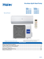
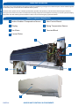
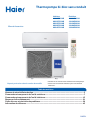
Ductless Split Heat Pump
Service Manual
Design may vary by model number.
• Please read this manual before using the heat pump.
• Keep this user manual for future reference.
PAGE 1
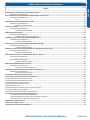
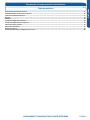
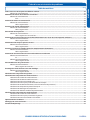
Safety Precautions/Introduction .................................................................................................3
Outdoor Unit Controls and Components ..................................................................................... 7
Indoor Unit Controls and Components ......................................................................................15
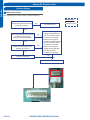
Sequence Of Operation ............................................................................................................. 21
Error Codes and Problem Solving ..............................................................................................29
Reference Information ..............................................................................................................43
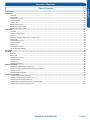
Table of Contents
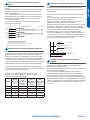
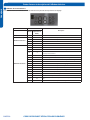
Indoor
AW09ES2VHB
AW12ES2VHB
AW15ES2VHB
AW18ES2VHB
AW24ES2VHB
Outdoor
1U09AP2VHA
1U12AP2VHA
1U15AP2VHA
1U18AP2VHA
1U24AP2VHA

[This page intentionally left blank.]

INTRODUCTION
PAGE 3
ENGLISH
Introduction
Safety Precautions ............................................................................................................................................................. 4
Warning and Cautions ......................................................................................................................................................................4
Introduction to System ......................................................................................................................................................5
Specicationsforproperoperationshouldbefollowed ................................................................................................................ 5
FundamentalTheoryOfHowSystemWorks..................................................................................................................................5
Table of Contents

INTRODUCTION
PAGE 4
ENGLISH
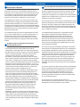
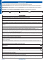
• Read these Safety Precautions carefully to ensure correct installation.
• This manual classies the precautions by WARNING and CAUTION.
• Follow all precautions below. They are all important for ensuring safety and preventing property/equipment damage.
!
WARNING: Failure to follow any of WARNING is likely to result in grave consequences such as death or serious injury.
!
CAUTION: Failure to follow any of CAUTION may, in some cases, result in grave consequences.
• The following safety symbols are used throughout this manual:
Observe this instruction
Establish an earth connection
Never attempt
• After completing installation, test the unit to check for installation errors. Give the user adequate instructions concerning the
use and cleaning of the unit according to the Operation Manual.
!
WARNING
• Installation should be performed by the dealer or another professional.
Improper installation may cause water leakage, electrical shock, or re.
• Install the heat pump according to the instructions given in this manual.
Incomplete installation may cause water leakage, electrical shock, or re.
• Use only the supplied or specied installation parts.
Use of other parts may cause the unit to come lose, water leakage, electrical shock, or re.
• Install the heat pump on a solid base that can support the unit’s weight.
An inadequate base or incomplete installation may cause injury in the event the unit falls o the base.
• Electrical work should be carried out in accordance with the installation manual and national/local electrical wiring codes and
rules of practice.
Insucient capacity or incomplete electrical work may cause electrical shock or re.
• Use a dedicated power circuit. Never use a power supply shared by another appliance.
• For wiring, use a cable long enough to cover the entire distance with no splices.
Do not use an extension cord. Do not put other loads on the power supply, use a dedicated power circuit.
(Failure to do so may cause abnormal heat, electric shock or re.)
• Use only the specied wire types for electrical connections between the indoor and outdoor units.
Firmly clamp the interconnecting wires so they receive no external stresses. Incomplete connections or clamping may cause terminal over-
heating or re.
• After completing interconnecting and supply wiring connections, shape the cables so that they do not put undue force on
the electrical covers or panels.
Install covers over the wires. Incomplete cover installation may cause terminal overheating, electrical shock, or re.
• If any refrigerant has leaked out during the installation work, ventilate the room.
(The refrigerant produces a toxic gas if exposed to ame.)
• After all installation is complete, check for and repair any system refrigerant leaks.
(The refrigerant produces a toxic gas if exposed to ames.)
•When installing or relocating the system, keep the refrigerant circuit free from substances other than the specied
refrigerant (R410A), such as air.
(The presence of air or other foreign substance in the refrigerant circuit causes an abnormal pressure rise or rupture, resulting in injury.)
• During pump-down, stop the compressor before removing the refrigerant piping.
If the compressor is still running, and the stop valve is open during pump-down, air will be sucked into the system while the compressor is
running. This will cause abnormal pressure and noncondensables added to the system.
• Be sure to establish a ground. Do not ground the unit to a utility pipe, arrester, or telephone earth.
An complete earth may cause electrical shock, or re. A high surge current from lightning or other sources may
cause damage to the heat pumpheat pump.
!
CAUTION
• Do not install the heat pump in a place where there is danger of exposure to ammable gas.
If the gas builds up around the unit, it may catch re.
• Install drain piping according to the instructions of this manual.
Inadequate piping may cause ooding.
•Tighten the are nut according to the specied torque using a torque wrench.
If the are nut is overtightened, the are nut may eventually crack and cause refrigerant leakage.
• Provide adequate measures to prevent the outdoor unit from being used as a shelter by rodents.
Rodents making contact with electrical parts can cause malfunctions, smoke or re. Please instruct the customer to keep the area around
the unit clean.
Safety Precautions

INTRODUCTION
PAGE 5
ENGLISH
Introduction to System
Single Zone Ductless Split System Heat Pumps feature a wall
mounted indoor fan/evaporator unit that receives refrigerant
from an inverter driven variable speed outdoor condensing
unit. The system operation is controlled with a remote
control.
The outdoor unit features a variable speed rotary
compressor, EEV metering device and DC fan motor. These
systems use R410A refrigerant and PVE oil. The outdoor units
are 208/230 volt rated systems. They come factory charged
for up to 25 ft. of interconnecting piping.
The indoor units are wall mounted type. They feature a DC
blower motor and a DC louver motor. The unit has a room
temperature sensor and an evaporator tube temperature
sensor. The wall unit is powered by voltage from the outdoor
unit.
Specications for proper operation should be followed
• The systems are designed to operate in room temperature
ranges of 60°F to 86°F in cooling mode and 60°F to 86°F in
heat mode.
• PVE oil is non reactive to water and will not go into
Hydrolysis. There is no need to add a refrigeration drier
when servicing or installing this system.
• The indoor wall mounted unit receives operating voltage
and communication data signals on #14 AWG wire that
connects between the indoor and outdoor units. There
should not be any splices in the eld wiring that goes
between terminals 1, 2, 3 and 4. A splice in these wires may
cause the system to lose communication between the
indoor and outdoor units. The system will then display an
error code E7.
• The systems come with enough factory charge for up to
25 feet of connecting refrigeration tubing. The tubing
connects using are type ttings at both the indoor and
outdoor units. Tubing must be sized per the specications.
Both lines must be insulated. The only method of checking
charge or adjusting charge is by weight method explained in
this manual (no exceptions).
• The condensate system is a gravity type. A eld installed
condensate pump may be added to the system. Always
follow the manufacturer’s installation instructions when
installing a condensate pump.
• Proper clearances at both indoor and outdoor units must be
maintained. Improper clearances cause system conditions
that include high refrigerant pressure, low refrigerant
pressure and indoor coil freezing problems.
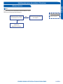
Fundamental Theory of How the System Works
The indoor unit will sense room temperature at the point
where the wall unit is installed. The indoor fan will run
continuously when placed in heating or cooling mode
operation and will not cycle on and o with the outdoor
unit. If it did, room temperature could not be sensed or
Introduction
maintained.
The inverter compressor system in the outdoor unit will vary
the refrigerant ow and indoor air volume levels to match
the cooling requirement inside the conditioned space. If an
abnormal condition is detected by the system’s sensors, the
system has the ability to take reactive measures.
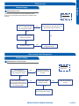
The amount of refrigerant ow and associated capacity
generated by the system will be determined by how fast the
system’s variable speed rotary compressor is pumping. The
compressor operating speed requirement is determined by
the dierence between the conditioned space temperature
versus the set point established by the homeowner’s remote
control.
If a large amount of capacity is needed, the compressor will
operate at a high frequency speed. As the need for capacity
reduces and the temperature of the room nears set point,
the compressor will slow down. When set point has been
reached, the compressor will shut o but the indoor fan
will continue to operate. Once a dierence in temperature
is sensed between remote control set point temperature
and room temperature, the compressor will restart at a new
calculated speed.
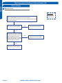
If a system sensor determines there is a need to adjust
the frequency signal to prevent a system malfunction,
the compressor frequency may be over ridden and a new
frequency established. It should be noted that the frequency
signal level that is sent to the compressor cannot be
determined by a servicing technician.
In this manual, system components, operation, sensor
functions and diagnostic procedures will be explained in
greater detail.

INTRODUCTION
PAGE 6
ENGLISH
[Thispageintentionallyleftblank.]

OUTDOOR UNIT CONTROLS & COMPONENTS
PAGE 7
ENGLISH
Outdoor Unit Controls & Components
Table of Contents
Outdoor Unit Introduction .................................................................................................................................................8
Outdoor Component Identication ....................................................................................................................................8
Outdoor Main Control Board ..............................................................................................................................................9
Terminal Block .................................................................................................................................................................. 10
Reactor ............................................................................................................................................................................ 10
Compressor .....................................................................................................................................................................10
Outdoor Fan Motor ........................................................................................................................................................... 10
Discharge Temperature Sensor ........................................................................................................................................ 11
Defrost Temperature Sensor ............................................................................................................................................ 11
Outdoor Ambient Temperature Sensor ............................................................................................................................ 11
Suction Line Temperature Sensor ..................................................................................................................................... 11
4-Way Valve .....................................................................................................................................................................12
Electronic Expansion Valve ............................................................................................................................................... 12
Accumulator .................................................................................................................................................................... 12
Filters ............................................................................................................................................................................... 12
Electrical Base Pan Heater ................................................................................................................................................ 12
DIP Switch ........................................................................................................................................................................ 13

OUTDOOR UNIT CONTROLS & COMPONENTS
PAGE 8
ENGLISH
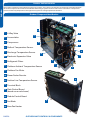
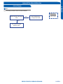
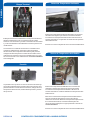
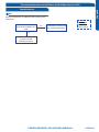
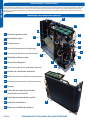
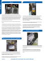
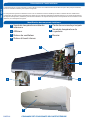
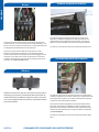
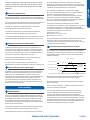
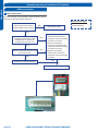
Outdoor Unit Introduction
The outdoor condensing unit models are heat pump systems. The outdoor unit has two circuit boards, a Module board that
drives the compressor and a Main Control Board that manages system functions and inverter calculations. Temperature
sensors monitor key temperatures throughout the system to manage operational decisions.
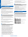
Outdoor Component Identication
4-Way Valve
Accumulator
Compressor
Defrost Temperature Sensor
Discharge Temperature Sensor
Electronic Expansion Valve
Refrigerant Filters
Outdoor Ambient Temperature Sensor
Outdoor Fan Motor
Power Factor Reactor
Suction Line Temperature Sensor
Terminal Block
Main Control Board
(board cover not shown)
Module Control Board
Fan Blade
Base Pan Heater
1
2
3
4
5
6
7
8
9
10
11
12
13
14
15
16
8
4
6
11
12
13
14
1
3
16
2
7
5
9
10
15

OUTDOOR UNIT CONTROLS & COMPONENTS
PAGE 9
ENGLISH
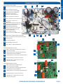
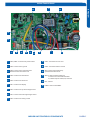
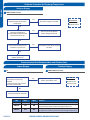
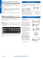
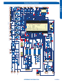
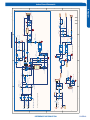
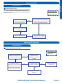
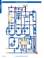
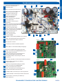
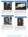
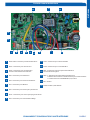
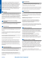
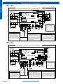
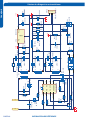
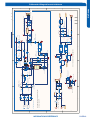
Outdoor Control Board
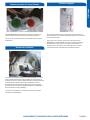
PCB (1) (Outdoor Control PCB)
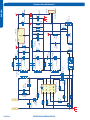
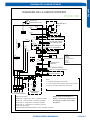
PCB (2) (Module PCB for 09-12K )
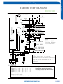
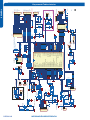
PCB (3) (Module PCB for 18-24K )
2
CN3 - Connector for ground
10
CN36 - Connector for communicate
between indoor and outdoor unit
6
CN11 - Connector for four way valve coil
4
CN9, CN8 - Connector for
CN2,CN1 on the module board
12
CN50 - Connector for DRED-control
09-12
18-24
8
CN24 - Communication connector for
control board and the module board
CN1, CN2 - Connector for power N and L
CN17, CN47 - Connector for
thermistors
7
CN23 - Connector for DC POWER
15V and 5V to the module board
3
CN15 - Connector for
electric expansion valves
11
CN28, CN25 - Connector to
P and N of the module board
9
CN22 - Connector for fan motor
5
FUSE 1: (25A, 250VAC); FUSE 2:(1A, 250VAC)
13
LED 1 - Constant ON is normal operation, ashing
indicates alarm.
14
RV1, RV2, RV3 Varistor
15
CN10 - Connector for the DC power 5V and 15V
form the control PCB
18
Base Pan Heater Connection
16
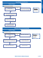
BM2-1, BM2-2 - Defrost DIP Switches
17
CN10 - Connector for the DC power 5V
and 15V form the control PCB
23
23
CN11 - Connector for communicate between the
control board and the module board
19
CN11 - Connector for communicate between the
control board and the module board
24
P (CN1), N (CN5) - Connector for capacitance board
20
P (CN8), N (CN9) - Connector for capacitance board
25
25
LI (CN7), LO (CN6) - Connector for reactor
21
21
LI (CN3), LO (CN4) - Connector for reactor
26
CN2, CN3, CN4 - Connector for the U, V, W
wire of the compressor
22
CN5, CN6, CN7 - Connector for the U, V, W
wire of the compressor
27
27
1
2
3
16
17
5
4
6
8
9
10
12
13
11
7
18
19
20
22
24
26
1

OUTDOOR UNIT CONTROLS & COMPONENTS
PAGE 10
ENGLISH
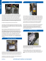
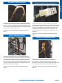
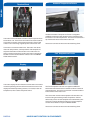
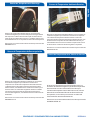
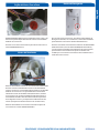
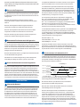
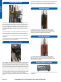
Terminal Block
Power Factor Reactor
The Reactor is an inductive lter that will aid in correction of
electrical power factor inuence of inverter capacitance. It is
unlikely to ever have an electrical failure of this component.
The Reactor is electrically connected to the Module Board on
terminal connections CN-7 and CN-8.
The outdoor unit is powered by 208/230 Volt Single Phase
electricity connected at the Outdoor Unit Terminal Block.
Terminals 1 and 2 on the outdoor unit terminal connect
this voltage to the system. The number 3 terminal is a
communication terminal that connects wiring between the
indoor and outdoor units. An earth ground source terminal
connects the outdoor unit to the line voltage power source.
Condensate safety switches should break wire 1.
The indoor unit is also powered by the same electrical supply
as the outdoor unit. #14 AWG wire is connected to the wiring
terminal block at the outdoor unit and is run to the indoor unit
wire terminal block.
When installing the eld supplied wiring, make certain the
wire gauge is correct. There should not be any electrical
wiring splices between the indoor unit and outdoor unit
wire. Wire #3 is used to carry communication data between
the indoor and outdoor units. A wiring splice where wires
are twisted in a wire nut may cause deformation of the
communication of the data signal. If communication is lost
between the indoor and outdoor units, an ERROR CODE E7
will occur.
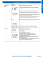
Compressor
Outdoor Fan Motor
The outdoor fan motor is a variable speed motor. The
required motor speed is calculated by the Main Control
Board. The motor is electrically connected to the Main
Control Board via PLUG CN-21.
In COOL MODE operation, the motor will slow down as
outdoor air temperature falls. In HEAT MODE operation, the
motor will increase speed as the outdoor air temperature
falls.
The compressor is a three phase DC inverter driven Rotary
type. The compressor is capable of variable speed operation.
The compressor operating frequency will be determined by
the temperature dierence between set point and room or
outdoor air temperature. (Cool Mode versus Heat Mode)
The compressor is electrically connected to the Module
Board on terminal connections CN-2, CN-3 and CN-4.
The compressor has an internal temperature overload that
will open if the compressor becomes too hot. Additional
protection of the compressor will be provided by the
Compressor Discharge Temperature Sensor and Suction
Line Temperature Sensor.

OUTDOOR UNIT CONTROLS & COMPONENTS
PAGE 11
ENGLISH
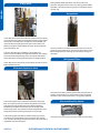
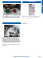
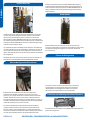
Discharge Temperature Sensor
Defrost Temperature Sensor
The Defrost Temperature Sensor is a negative coecient
thermistor that will change resistance in response to outdoor
coil temperature changes. The Main Control Board monitors
the temperature of the outdoor coil to determine when the
system is needing to perform a defrost cycle. The sensor also
monitors outdoor coil temperature during defrost cycles to
determine termination conditions.
This sensor connects to the Main Control Board at PLUG
CN-19.
The Discharge Temperature Sensor is a Negative Coecient
thermistor that senses the temperature of the compressor
hot gas. The Main Control Board monitors the temperature of
the compressor hot gas and will make inverter speed changes
in response to input from this device.
This sensor connects to the Main Control Board at PLUG
CN-17.
Outdoor Ambient Temperature Sensor
Suction Line Temperature Sensor
The Suction Line Temperature Sensor is a negative
coecient thermistor that senses the temperature of
the suction line. The Main Control Board monitors the
temperature of the suction line to determine EEV orice size
in an attempt to maintain proper operating superheat.
This sensor connects to the Main Control Board at PLUG
CN-18.
The Outdoor Ambient Temperature Sensor is a negative
coecient thermistor that will change resistance in response
to outdoor air temperature changes. The Main Control Board
monitors the temperature of the outdoor air to determine
outdoor fan speed requirements and inverter speed. The
sensor also plays a role in calculation of required defrost
conditions.
This sensor connects to the Main Control Board at PLUG
CN-20.

OUTDOOR UNIT CONTROLS & COMPONENTS
PAGE 12
ENGLISH
4-Way Valve
Electronic Expansion Valve
The metering device is an electronic expansion valve type
EEV. The valve consists of an electrical operator and a valve
body with internal variable size orice. When operating,
the Main Control Board will send pulses of voltage to the
electrical operator. The operator will then magnetically move
the position of the metering orice pin to vary its size.
The metering device position is determined by input from
a Suction Line Temperature Sensor located in the outdoor
unit. The EEV will change the internal orice size to maintain a
superheat level of around 10°F.
The 4-Way Valve redirects the ow of refrigerant in the piping
circuit to allow the system to swap the functions of the indoor
and outdoor coils. When de-energized in COOL MODE, the
valve will direct the refrigerant hot gas to the outdoor coil.
When energized in HEAT MODE, the valve will direct the hot
gas to the indoor coil.
The valve ow direction capability is controlled by an
electrical solenoid. When energized by 240 Volts, line voltage,
the solenoid will magnetically move an internal slide within
the 4-Way Valve to change the direction of refrigerant ow.
The 4-Way Valve is electrically connected to the Main Control
Board at PLUG CN-10.
Accumulator
The Accumulator is located in the suction line circuit at the
entrance to the compressor. The accumulator helps prevent
liquid refrigerant from entering the compressor during run
operation.
Refrigerant Filters
Electrical Base Pan Heater
The system has debris catching lters that protect internal
system components from contaminants in the refrigerant.
The lter is a permanent part that is not typically replaced.
During COOL MODE operation, the valve meters low
pressure refrigerant to the indoor coil. During HEAT MODE
operation, the valve meters low pressure refrigerant to the
outdoor coil.
The system has an electrical base pan heater for defrosting.

OUTDOOR UNIT CONTROLS & COMPONENTS
PAGE 13
ENGLISH
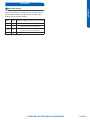
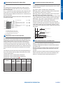
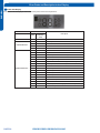
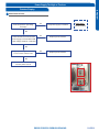
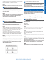
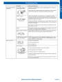
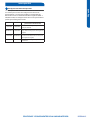
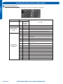
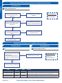
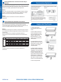
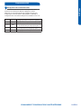
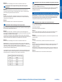
DIP Switch
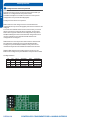
DIP Switch Settings
The outdoor unit PCB board DIP switches are used to control
defrost cycle settings. The DIP switches are factory set for
Demand Defrost (BM2-1 ON, BM2-2 ON). The DIP switch
settings may be adjusted as follow:
BM2-1 BM2-2 Description - (Defrost is generally every 45 minutes)
OFF OFF Demand defrost for cold climate (default)
ON OFF
Time defrost at lower frequency
(10 Hz lower than the regular defrost)
OFF ON
Time defrost at higher frequency
(10 Hz higher than the regular defrost)
ON ON Demand defrost for moderate climate

INDOOR UNIT CONTROLS & COMPONENTS
PAGE 14
ENGLISH
[Thispageintentionallyleftblank.]

INDOOR UNIT CONTROLS & COMPONENTS
PAGE 15
ENGLISH
Indoor Unit Controls & Components
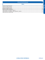
Table of Contents
Indoor Unit Introduction .................................................................................................................................................. 16
Indoor Component Identication ..................................................................................................................................... 16
Indoor Control Board ........................................................................................................................................................17
Terminal Block .................................................................................................................................................................. 18
Display .............................................................................................................................................................................18
Ambient Temperature Sensor .......................................................................................................................................... 18
Coil Temperature Sensor .................................................................................................................................................. 18
Louver Motor ................................................................................................................................................................... 19
Fan Motor ......................................................................................................................................................................... 19
Emergency Button ........................................................................................................................................................... 19
DIP Switch and DIP Switch Settings .................................................................................................................................. 20

INDOOR UNIT CONTROLS & COMPONENTS
PAGE 16
ENGLISH
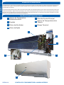
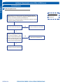
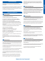
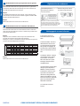
Indoor Component Identication
Indoor Unit Introduction
The indoor unit is mounted high on the wall to provide air conditioning coverage of a conditioned space. Field installed/supplied
condensate pump accessories can be added to these systems.
Features of the system include: Variable speed blower operation that speeds up and slows down with changes in demand,
Moving louvers to direct air, Indoor air temperature sensing, Evaporator coil temperature sensing, Consumer operation display,
Evaporator coil with metering device located in outdoor unit, and an Emergency Operation Switch.
Indoor Ambient Temperature Sensor
Display
Fan Motor
Louver Motor
1
2
3
4
Main Control Board
Piping Temperature Sensor
Terminal Block
5
6
7
5
7
6
4
1
3
2

INDOOR UNIT CONTROLS & COMPONENTS
PAGE 17
ENGLISH
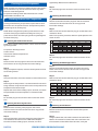
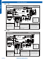
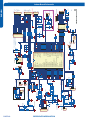
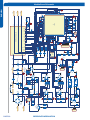
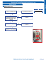
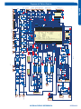
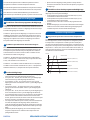
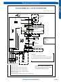
Indoor Control Board
2
2
CN27 - Connector for ground
4
4
CN6 - Connector for thermistors
9
9
CN2 - Connector for wiring-control
6
6
CN7 - Connector for display
11
11
CN34 - Connector for Wi-Fi-control
RV1 - Varistor
13
13
SW2 – 1-Select remote code A or B,
2-Select room card enable or disable
3,4-Select eeprom code 23, 26, 33 and 35
CN21, CN52 - Connector for power N and L
1
CN11 - Connector for left-right stepper motor
8
8
CN9 - Connector for fan motor
5
5
SW1 - Connector for Emergency
operation ON / OFF switch
12
15
15
CN23 - Connector for communication
between indoor and outdoor unit
3
3
CN51 - Connector for room card
10
10
CN5 - Connector for up-down stepper motor
7
7
14
14
FUSE1 - Fuse 3.15A/250VAC
12

INDOOR UNIT CONTROLS & COMPONENTS
PAGE 18
ENGLISH
Terminal Block
Display
The indoor unit terminal block receives electrical power from
the outdoor unit. There are 4 connections for electrical wires.
Terminals 1 and 2 are connected to terminals 1 and 2 of the
outdoor unit. This wiring supplies power to the indoor unit.
Terminal 3 is a communication wire. The indoor unit sends
indoor air temperature, coil temperature and temperature
setpoint information to the outdoor unit on this wire. If a
splice or break in this wire is present, the indoor unit will not
be able to communicate with the outdoor unit. The ERROR
CODE will be code E7.
The indoor display has an infrared communication circuit that
receives operating commands from the remote control. This
display will indicate operating modes, error codes, indoor air
temperature, timer status and power status.
Ambient Temperature Sensor
The Room Ambient Temperature Sensor is a negative
coecient thermistor that will decrease in resistance with
increases in room air temperature. The sensor is located on a
clip mounted to the surface of the indoor coil.
The sensor connects to the control board at Plug CN-6.
Coil Temperature Sensor
The Coil Temperature Sensor is a negative coecient
thermistor that will decrease in resistance with increases in
coil temperature. The sensor is located in a socket soldered
to the surface of the indoor coil.
This sensor will monitor the temperature of the indoor coil
in both cooling and heating modes of operation. Should
abnormally cold or hot coil temperature be detected by this
sensor, the system will take functional corrective steps to
correct the condition or report an ERROR CODE.
The sensor connects to the control board at Plug CN-6.

INDOOR UNIT CONTROLS & COMPONENTS
PAGE 19
ENGLISH
Stepper Motor Louver
Fan Motor
Emergency Button
The Indoor Fan Motor is a variable speed motor. The
motor will vary speed with the speed of the compressor
inverter. The speed can also be set at the remote control
or automatically adjusted using the AUTO fan mode. When
in AUTO fan mode, the speed of the fan is calculated using
the indoor set temperature and the indoor room ambient
temperature. (Outdoor air temperature in heat mode.)
The Fan Motor is connected to the indoor control board via
PLUG CN-9.
If the remote control is non-functional, the Emergency
Button can be accessed by swinging open the front of the wall
unit. The button is located on the right side.
Pushing this button will activate AUTO MODE operation.
AUTO MODE activated with this button will maintain 75°F.
The system will stay in this mode until commands are
received by the indoor unit communication circuit via the
remote control.
The STEPPER MOTOR moves the louver up or down, and
right or left depending upon selections made at the remote
control.
The motor is connected to the indoor control board at PLUG
CN-11.

INDOOR UNIT CONTROLS & COMPONENTS
PAGE 20
ENGLISH
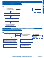
DIP Switch Settings
The PCB for the indoor unit of the Advanced series of single
zone mini-splits has a set of DIP switches that must be set
when replacing the PCB.
The replacement PCB is shipped with all switches set to the
OFF position.
Switch settings:
SW2-1 Selects remote code A or B. Normally set to the o
position for code A operation.
If two indoor units are used in the same area and the user
wishes to control them separately, switch SW2-1 of the
second unit is set to the ON position for code B operation.
The wireless remote for the second unit is also set to code B.
SW2-2 Selects room card enable or disable.
Normally set to the OFF position. Set to the ON position
when used in conjunction with a room card interface utilized
in hotel rooms.
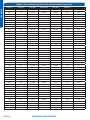
SW-3 & SW-4 Selects eeprom code 23, 26, 33 and 35. Set to
identify the tonnage of the unit.
Settings:
9K (23) SW-3 OFF SW-4 OFF
12K (26) SW-3 OFF SW-4 ON
15K (33) SW-3 ON SW-4 OFF
18K (33) SW-3 ON SW-4 OFF
24K (35) SW-3 ON SW-4 ON
DIP Switch
La page est en cours de chargement...
La page est en cours de chargement...
La page est en cours de chargement...
La page est en cours de chargement...
La page est en cours de chargement...
La page est en cours de chargement...
La page est en cours de chargement...
La page est en cours de chargement...
La page est en cours de chargement...
La page est en cours de chargement...
La page est en cours de chargement...
La page est en cours de chargement...
La page est en cours de chargement...
La page est en cours de chargement...
La page est en cours de chargement...
La page est en cours de chargement...
La page est en cours de chargement...
La page est en cours de chargement...
La page est en cours de chargement...
La page est en cours de chargement...
La page est en cours de chargement...
La page est en cours de chargement...
La page est en cours de chargement...
La page est en cours de chargement...
La page est en cours de chargement...
La page est en cours de chargement...
La page est en cours de chargement...
La page est en cours de chargement...
La page est en cours de chargement...
La page est en cours de chargement...
La page est en cours de chargement...
La page est en cours de chargement...
La page est en cours de chargement...
La page est en cours de chargement...
La page est en cours de chargement...
La page est en cours de chargement...
La page est en cours de chargement...
La page est en cours de chargement...
La page est en cours de chargement...
La page est en cours de chargement...
La page est en cours de chargement...
La page est en cours de chargement...
La page est en cours de chargement...
La page est en cours de chargement...
La page est en cours de chargement...
La page est en cours de chargement...
La page est en cours de chargement...
La page est en cours de chargement...
La page est en cours de chargement...
La page est en cours de chargement...
La page est en cours de chargement...
La page est en cours de chargement...
La page est en cours de chargement...
La page est en cours de chargement...
La page est en cours de chargement...
La page est en cours de chargement...
La page est en cours de chargement...
La page est en cours de chargement...
La page est en cours de chargement...
La page est en cours de chargement...
La page est en cours de chargement...
La page est en cours de chargement...
La page est en cours de chargement...
La page est en cours de chargement...
La page est en cours de chargement...
La page est en cours de chargement...
La page est en cours de chargement...
La page est en cours de chargement...
La page est en cours de chargement...
La page est en cours de chargement...
La page est en cours de chargement...
La page est en cours de chargement...
La page est en cours de chargement...
La page est en cours de chargement...
La page est en cours de chargement...
La page est en cours de chargement...
La page est en cours de chargement...
La page est en cours de chargement...
La page est en cours de chargement...
La page est en cours de chargement...
La page est en cours de chargement...
La page est en cours de chargement...
La page est en cours de chargement...
La page est en cours de chargement...
La page est en cours de chargement...
La page est en cours de chargement...
La page est en cours de chargement...
La page est en cours de chargement...
La page est en cours de chargement...
La page est en cours de chargement...
La page est en cours de chargement...
La page est en cours de chargement...
La page est en cours de chargement...
La page est en cours de chargement...
La page est en cours de chargement...
La page est en cours de chargement...
La page est en cours de chargement...
La page est en cours de chargement...
La page est en cours de chargement...
La page est en cours de chargement...
La page est en cours de chargement...
La page est en cours de chargement...
La page est en cours de chargement...
La page est en cours de chargement...
La page est en cours de chargement...
La page est en cours de chargement...
La page est en cours de chargement...
La page est en cours de chargement...
La page est en cours de chargement...
La page est en cours de chargement...
La page est en cours de chargement...
La page est en cours de chargement...
La page est en cours de chargement...
La page est en cours de chargement...
La page est en cours de chargement...
La page est en cours de chargement...
La page est en cours de chargement...
La page est en cours de chargement...
La page est en cours de chargement...
La page est en cours de chargement...
La page est en cours de chargement...
La page est en cours de chargement...
La page est en cours de chargement...
La page est en cours de chargement...
La page est en cours de chargement...
La page est en cours de chargement...
La page est en cours de chargement...
La page est en cours de chargement...
La page est en cours de chargement...
La page est en cours de chargement...
La page est en cours de chargement...
La page est en cours de chargement...
La page est en cours de chargement...
La page est en cours de chargement...
La page est en cours de chargement...
La page est en cours de chargement...
La page est en cours de chargement...
La page est en cours de chargement...
La page est en cours de chargement...
La page est en cours de chargement...
La page est en cours de chargement...
La page est en cours de chargement...
La page est en cours de chargement...
La page est en cours de chargement...
La page est en cours de chargement...
La page est en cours de chargement...
La page est en cours de chargement...
La page est en cours de chargement...
La page est en cours de chargement...
La page est en cours de chargement...
La page est en cours de chargement...
La page est en cours de chargement...
La page est en cours de chargement...
La page est en cours de chargement...
La page est en cours de chargement...
La page est en cours de chargement...
La page est en cours de chargement...
La page est en cours de chargement...
La page est en cours de chargement...
La page est en cours de chargement...
La page est en cours de chargement...
La page est en cours de chargement...
La page est en cours de chargement...
La page est en cours de chargement...
La page est en cours de chargement...
La page est en cours de chargement...
-
 1
1
-
 2
2
-
 3
3
-
 4
4
-
 5
5
-
 6
6
-
 7
7
-
 8
8
-
 9
9
-
 10
10
-
 11
11
-
 12
12
-
 13
13
-
 14
14
-
 15
15
-
 16
16
-
 17
17
-
 18
18
-
 19
19
-
 20
20
-
 21
21
-
 22
22
-
 23
23
-
 24
24
-
 25
25
-
 26
26
-
 27
27
-
 28
28
-
 29
29
-
 30
30
-
 31
31
-
 32
32
-
 33
33
-
 34
34
-
 35
35
-
 36
36
-
 37
37
-
 38
38
-
 39
39
-
 40
40
-
 41
41
-
 42
42
-
 43
43
-
 44
44
-
 45
45
-
 46
46
-
 47
47
-
 48
48
-
 49
49
-
 50
50
-
 51
51
-
 52
52
-
 53
53
-
 54
54
-
 55
55
-
 56
56
-
 57
57
-
 58
58
-
 59
59
-
 60
60
-
 61
61
-
 62
62
-
 63
63
-
 64
64
-
 65
65
-
 66
66
-
 67
67
-
 68
68
-
 69
69
-
 70
70
-
 71
71
-
 72
72
-
 73
73
-
 74
74
-
 75
75
-
 76
76
-
 77
77
-
 78
78
-
 79
79
-
 80
80
-
 81
81
-
 82
82
-
 83
83
-
 84
84
-
 85
85
-
 86
86
-
 87
87
-
 88
88
-
 89
89
-
 90
90
-
 91
91
-
 92
92
-
 93
93
-
 94
94
-
 95
95
-
 96
96
-
 97
97
-
 98
98
-
 99
99
-
 100
100
-
 101
101
-
 102
102
-
 103
103
-
 104
104
-
 105
105
-
 106
106
-
 107
107
-
 108
108
-
 109
109
-
 110
110
-
 111
111
-
 112
112
-
 113
113
-
 114
114
-
 115
115
-
 116
116
-
 117
117
-
 118
118
-
 119
119
-
 120
120
-
 121
121
-
 122
122
-
 123
123
-
 124
124
-
 125
125
-
 126
126
-
 127
127
-
 128
128
-
 129
129
-
 130
130
-
 131
131
-
 132
132
-
 133
133
-
 134
134
-
 135
135
-
 136
136
-
 137
137
-
 138
138
-
 139
139
-
 140
140
-
 141
141
-
 142
142
-
 143
143
-
 144
144
-
 145
145
-
 146
146
-
 147
147
-
 148
148
-
 149
149
-
 150
150
-
 151
151
-
 152
152
-
 153
153
-
 154
154
-
 155
155
-
 156
156
-
 157
157
-
 158
158
-
 159
159
-
 160
160
-
 161
161
-
 162
162
-
 163
163
-
 164
164
-
 165
165
-
 166
166
-
 167
167
-
 168
168
-
 169
169
-
 170
170
-
 171
171
-
 172
172
-
 173
173
-
 174
174
-
 175
175
-
 176
176
-
 177
177
-
 178
178
-
 179
179
-
 180
180
-
 181
181
-
 182
182
-
 183
183
-
 184
184
-
 185
185
-
 186
186


Haier 1U09AP2VHA Manuel utilisateur
- Catégorie
- Climatiseurs split-system
- Taper
- Manuel utilisateur
- Ce manuel convient également à
dans d''autres langues
- English: Haier 1U09AP2VHA User manual
- español: Haier 1U09AP2VHA Manual de usuario
Documents connexes
Autres documents
-
Fujitsu AOTG45LBLA6 Guide d'installation
-
Hitachi RAC-D18EX3 Manuel utilisateur
-
-
-
-
 Olimpia Splendid Sherpa AQUADUE S2 Manuale d'installazione
-
-
-
Fujitsu AUGA36FRTA Guide d'installation
-
