
750
100
350
32
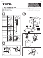
AUTO FAUCET
03B54S T3 2009.3
A
K
B
C
E
D
O
L
M
N
F
G
H
TN78-9 V465
TN78-9 V565
TN78-9 V765
2
3
A
D
!
ROBINET AUTO
RUBINETTO AUTO
AUTO WASSERHAHN
GB
FR
D
IT
Single supply faucet
Robinet à alimentation unique
Rubinetto fornitura singola
Einzelner wasserhahn
TEN40AW V105
TEN40AW V205
TEN12W V105
TEN12W V205
TEN12W V305
TEN12W V505
G1/2
4
9
1
5
8
2 3
6
10
7
Installationsanleitung
D
Installation Manual
GB
Manuel D'installation
FR
Manuale Di installazione
IT
B
B
K
E
F
G
H
C
C
K
C
K
!
B
C
K
L
M
K
90
E
L
4 7
8
5
6
1
2

B
B
K
E
F
G
H
C
C
K
C
K
!
B
C
K
L
M
K
90
E
L
4 7
8
5
6
1
2

N
O
A
!
9
10
1
2
TEN40AW V205
TEN40AW V105
TEN12AW V505 TEN12AW V205
TEN12AW V105
TEN12AW V305
Ausguss
Betriebsdru
ckbereich
minimal Wasserdruck
0.05 Mpa (Fließdruck)
Nachweisbereich
des Sensors
130-200mm
Der Sensor ist selbstregulierend
maximal Wasserdruck
0.8 MPa(hydrostatisch)
Flussrate 3L/min.2L/min. 4L/min.
Steuergerät
TN78-9 V465 TN78-9 V565TN78-9 V765
Betriebstemperatur
Wasseranschluss
R1/2
Aufbauzeichnung
Bauteile
TEN40AW V205
TEN40AW V105
TEN12AW V505 TEN12AW V205
TEN12AW V105
TEN12AW V305
Beccuccio
Intervallo pressione
di utilizzo
Minima pressione acqua richiesta
0.05MPa (pressione flusso)
Rilevamento intervallo
per sensore
130-200mm
Il sensore si regola automaticamente
Massima pressione acqua richiesta
0.8MPa(idrostatica)
Velocità flusso 3L/min.2L/min. 4L/min.
Controllore
TN78-9 V465 TN78-9 V565TN78-9 V765
Temperatura ambiente
di utilizzo
Ingresso acqua
R1/2
Specifiche tecniche
Utilizzo
Procedura
Diagramma Impostazione
Componente
TEN40AW V205
TEN40AW V105
TEN12AW V505 TEN12AW V205
TEN12AW V105
TEN12AW V305
Bec verseur
Plage de pression
d'alimentation
Pression minimum
0.05MPa (débit pression)
Plage de détection
du capteur
30-200mm
Capteur autorégleur
Pression maximum
0.8MPa(hydrostatique)
Débit 3L/mn2L/mn 4L/mn
Contrôleur
TN78-9 V465 TN78-9 V565TN78-9 V765
Environnement
d'eploitation
Entrée d'eau
R1/2
Caractéristiques techniques
Fonctionnement
Méthode
Plan de pose
Composant
Déposer de cache du contrôleur.
Engager le connecteur de la batterie de secours jusqu'à ce qu'il émette un déclic.
Monter le bec verseur.
Fixer le support d'eau au mur.
Relier le contrôleur au support d'entrée d'eau.
Si nécessaire, couper le flexible.
Relier le flexible.
Engager le connecteur du capteur (vert) jusqu'à ce qu'il émette un déclic.
Poser le cache du contrôleur.
Faites une chasse complète des tubes.
Rimuovere coperchio controllore.
Inserire il connettore (bianco) della batteria di riserva finché non si arresta facendo click.
Installare il beccuccio.
Montare sulla parete la staffa dell'acqua.
Collegare il controllore alla staffa di ingresso acqua.
Se necessario tagliare il manicotto.
Collegare il manicotto.
Inserire il connettore (verde) del sensore finché non si arresta facendo click.
Applicare il coperchio del controllore.
Irrigare bene i tubi
TEN40AW V205
TEN40AW V105
TEN12AW V505 TEN12AW V205
TEN12AW V105
TEN12AW V305
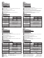
Spout
Operating pressure
range
minimum water pressure
0.05MPa(flow pressure)
Detection range
for sensor
130-200mm
Sensor is self-adjusting
maximum water pressure
0.8MPa(hydrostatic)
Flow rate 3L/min.2L/min. 4L/min.
Controller
TN78-9 V465 TN78-9 V565TN78-9 V765
Operating environment
temperature
Water inlet
R1/2
Specification
Operation
Technische Daten
Betrieb
Procedure
Set-up Drawing
Component
Firmensitz
D
Head Office
GB
Siége social
FR
Sede centrale
IT
TOTO Ltd. All rights reserved.
TOTO Ltd. Alle Rechte vorbehalten.
TOTO Ltd. Tous draits réservés.
TOTO Ltd. Tutb i diritti riservati.
Peter-Müller-str.16 D-40468 Düsseldorf Germany
TOTO Europe GmbH
Tel: +49(0)700 8686 0700
Printed in Japan.
Gedruckt in Japan.
Imprimé au Japon.
Stampabo in Giappone.
GB D
FR IT
1 40
1 40
1 40
1 40
Vorgehen
2
3
4
5
6
7
8
9
10
1
Die Abdeckung für die Steuerung entfernen.
Den Stecker (weiß) für die Stützbatterie soweit einstecken, bis er einrastet.
Den Ausguss installieren.
Die Wasserrohrhalterung an der Wand montieren.
Das Steuergerät an die Halterung für den Wasserzulauf anschließen.
Falls erforderlich den Verbindungsschlauch für zurechtschneiden.
Den Verbindungsschlauch für.
Den Sensorstecker (grün) soweit einstecken, bis er einrastet.
Die Abdeckung für die Steuerung entfernen.
Rohre gründlich ausspülen.
2
3
4
5
6
7
8
9
10
1
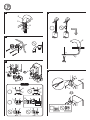
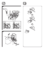
Remove the controller cover.
Insert the (white) connector of backup battery till it stops with a click.
Fasten the spout.
Mount the water bracket on the wall.
Connect the controller to the water inlet braket.
Cut the hose if necessary.
Connect the hose.
Insert the sensor connector(green).till it stops with a click.
Attach the controller cover.
Flush pipes throughly.
2
3
4
5
6
7
8
9
10
1
2
3
4
5
6
7
8
9
10
1

TEN40AW V205
TEN40AW V105
TEN12AW V505 TEN12AW V205
TEN12AW V105
TEN12AW V305
Ausguss
Betriebsdru
ckbereich
minimal Wasserdruck
0.05 Mpa (Fließdruck)
Nachweisbereich
des Sensors
130-200mm
Der Sensor ist selbstregulierend
maximal Wasserdruck
0.8 MPa(hydrostatisch)
Flussrate 3L/min.2L/min. 4L/min.
Steuergerät
TN78-9 V465 TN78-9 V565TN78-9 V765
Betriebstemperatur
Wasseranschluss
R1/2
Aufbauzeichnung
Bauteile
TEN40AW V205
TEN40AW V105
TEN12AW V505 TEN12AW V205
TEN12AW V105
TEN12AW V305
Beccuccio
Intervallo pressione
di utilizzo
Minima pressione acqua richiesta
0.05MPa (pressione flusso)
Rilevamento intervallo
per sensore
130-200mm
Il sensore si regola automaticamente
Massima pressione acqua richiesta
0.8MPa(idrostatica)
Velocità flusso 3L/min.2L/min. 4L/min.
Controllore
TN78-9 V465 TN78-9 V565TN78-9 V765
Temperatura ambiente
di utilizzo
Ingresso acqua
R1/2
Specifiche tecniche
Utilizzo
Procedura
Diagramma Impostazione
Componente
TEN40AW V205
TEN40AW V105
TEN12AW V505 TEN12AW V205
TEN12AW V105
TEN12AW V305
Bec verseur
Plage de pression
d'alimentation
Pression minimum
0.05MPa (débit pression)
Plage de détection
du capteur
30-200mm
Capteur autorégleur
Pression maximum
0.8MPa(hydrostatique)
Débit 3L/mn2L/mn 4L/mn
Contrôleur
TN78-9 V465 TN78-9 V565TN78-9 V765
Environnement
d'eploitation
Entrée d'eau
R1/2
Caractéristiques techniques
Fonctionnement
Méthode
Plan de pose
Composant
Déposer de cache du contrôleur.
Engager le connecteur de la batterie de secours jusqu'à ce qu'il émette un déclic.
Monter le bec verseur.
Fixer le support d'eau au mur.
Relier le contrôleur au support d'entrée d'eau.
Si nécessaire, couper le flexible.
Relier le flexible.
Engager le connecteur du capteur (vert) jusqu'à ce qu'il émette un déclic.
Poser le cache du contrôleur.
Faites une chasse complète des tubes.
Rimuovere coperchio controllore.
Inserire il connettore (bianco) della batteria di riserva finché non si arresta facendo click.
Installare il beccuccio.
Montare sulla parete la staffa dell'acqua.
Collegare il controllore alla staffa di ingresso acqua.
Se necessario tagliare il manicotto.
Collegare il manicotto.
Inserire il connettore (verde) del sensore finché non si arresta facendo click.
Applicare il coperchio del controllore.
Irrigare bene i tubi
TEN40AW V205
TEN40AW V105
TEN12AW V505 TEN12AW V205
TEN12AW V105
TEN12AW V305
Spout
Operating pressure
range
minimum water pressure
0.05MPa(flow pressure)
Detection range
for sensor
130-200mm
Sensor is self-adjusting
maximum water pressure
0.8MPa(hydrostatic)
Flow rate 3L/min.2L/min. 4L/min.
Controller
TN78-9 V465 TN78-9 V565TN78-9 V765
Operating environment
temperature
Water inlet
R1/2
Specification
Operation
Technische Daten
Betrieb
Procedure
Set-up Drawing
Component
Firmensitz
D
Head Office
GB
Siége social
FR
Sede centrale
IT
TOTO Ltd. All rights reserved.
TOTO Ltd. Alle Rechte vorbehalten.
TOTO Ltd. Tous draits réservés.
TOTO Ltd. Tutb i diritti riservati.
Peter-Müller-str.16 D-40468 Düsseldorf Germany
TOTO Europe GmbH
Tel: +49(0)700 8686 0700
Printed in Japan.
Gedruckt in Japan.
Imprimé au Japon.
Stampabo in Giappone.
GB D
FR IT
1 40
1 40
1 40
1 40
Vorgehen
2
3
4
5
6
7
8
9
10
1
Die Abdeckung für die Steuerung entfernen.
Den Stecker (weiß) für die Stützbatterie soweit einstecken, bis er einrastet.
Den Ausguss installieren.
Die Wasserrohrhalterung an der Wand montieren.
Das Steuergerät an die Halterung für den Wasserzulauf anschließen.
Falls erforderlich den Verbindungsschlauch für zurechtschneiden.
Den Verbindungsschlauch für.
Den Sensorstecker (grün) soweit einstecken, bis er einrastet.
Die Abdeckung für die Steuerung entfernen.
Rohre gründlich ausspülen.
2
3
4
5
6
7
8
9
10
1
Remove the controller cover.
Insert the (white) connector of backup battery till it stops with a click.
Fasten the spout.
Mount the water bracket on the wall.
Connect the controller to the water inlet braket.
Cut the hose if necessary.
Connect the hose.
Insert the sensor connector(green).till it stops with a click.
Attach the controller cover.
Flush pipes throughly.
2
3
4
5
6
7
8
9
10
1
2
3
4
5
6
7
8
9
10
1
-
 1
1
-
 2
2
-
 3
3
-
 4
4


dans d''autres langues
- italiano: Toto TEN40AW V105 Guida d'installazione
- English: Toto TEN40AW V105 Installation guide
- Deutsch: Toto TEN40AW V105 Installationsanleitung
Autres documents
-
Dell V105 All In One Inkjet Printer Mode d'emploi
-
Lincoln Electric Invertec V205-T AC/DC Mode d'emploi
-
-
-
Yamaha YDS-12 Le manuel du propriétaire
-
Epson ELPLX03 Ultra Short Throw Lens Mode d'emploi
-
Philips SCE1010/00 Product Datasheet
-
-
HP G510a Le manuel du propriétaire
-
Lincoln Electric Invertec V160-T PULSE Mode d'emploi