
Technical manual
EN
MARK COLDSTREAM
0665020_R02
Livret technique
FR
Technisch boek
NL

2

3
EN
Read this document before
installing the appliance
1.0 General
1.1 All rights reserved
The manufacturer has a policy of continuous product improvement and reserves the right to make
changes to the specications without prior notice. The technical details are considered correct but
do not form the basis for a contract or warranty. All orders are accepted subject to the standard
terms and conditions of sale and delivery (which will be sent to you at your request).
1.2 General warnings
Installation must comply with the relevant local and/or national regulations. You must therefore
have the ColdStream installed by a professionally qualied installer in accordance with all applicable
national and international regulations. Faulty installation, adjustment, alteration, maintenance activity
or repair shall render the warranty void.
The machine is conforming to the following European Community Directives:
2006/42/EEC Machinery Directive
2006/95/EEC Low Voltage Directive
2004/108/EEC Electromagnetic Compatibility Directive
1.3 Presentation of the ColdStream Evaporative Cooler
To improve the summer microclimate inside a production unit, sales or other area, it is necessary
to ventilate the environment with frequent changes of fresh, ltered and possibly cool air. For large
areas such as industrial buildings, an air conditioning plant is frequently not adaptable due to the
great volume of air to be cooled and the thermal loads of processes to be neutralized, the necessary
amount of energy is very high and the cooling effect is reduced by the exhaust air extraction plant
and by frequent opening of the doors during normal activity.
Evaporative cooling plants that cool the air using a natural principle represent an optimal solution:
the air passes through special wet water lters, loosing part of its heat during the evaporation
process of the water and hence lowering the air temperature. The absence of refrigeration plants
reduces energy consumption to a minimum and enables great volumes of air to be treated for the
many air changes necessary.
Warning
Incorrect installation, adjustment, alteration, repair or maintenance work may lead to material
damage or injury. All work must be carried out by certied, qualied professionals. If the
appliance is not positioned in accordance with the instructions, the warranty shall be rendered
void. This appliance is not intended for use by children or persons with a physical, sensory or
mental handicap, or who lack the required experience or expertise, unless they are supervised
or have been instructed in the use of the appliance by somebody who is responsible for their
safety.Children must be supervised to ensure that they do not play with the appliance.

4
1.4 Foreseen use
The ColdStream evaporative cooler can be installed in all environments where it is necessary to
improve the microclimate, where the environment must be ventilated with frequent changes of
fresh, ltered and possibly cool air, such as:
• production buildings and units;
• sales areas and warehouses;
• sport areas such as gymnasiums.
It is absolutely forbidden to make modications to the machine and its destination of use.
The supplier declines all responsibility for any damages which may be, directly or indirectly, caused
to exposed persons or property, due to improper use or use of the machine for different purposes
other than the design purposes, incorrect installation, inappropriate power supply, different or
changes to the installation environment from the one declared during order conrmation, grave
deciency of maintenance, unauthorized alterations and modications, use of non-original spare
parts, removal of the protection guards, inobservance of the instructions for use, negligence, etc..
The machine must NOT be used for a different use than its designed use for any reason
whatsoever or used in a different way than stated in this manual.
DO NOT install the machine in closed areas; the machine must be installed outside the area to be
treated, except by specic approval of the manufacturer.
Do NOT start-up the machine if it is not connected to the relative plant (duct) of air distribution.
When the plant is operating, do not touch the fan – Mechanical danger.
It is forbidden to work on moving parts.
It is absolutely forbidden to install ColdStream evaporative cooling plants in potentially explosive
environments.
1.5 Machineidenticationdata
Machine identication data is shown on the warranty sheet supplied to the customer and is
enclosed in the documentation and on the machine identication plate.
If Technical Assistance or spare parts are required, always supply the machine model and serial
number.
1.6 Electrical boards
Any electrical boards supplied by Mark Climate Technology. are manufactured according to EN
60204/1 regulations.
It is absolutely forbidden to make modications to the electrical board.
!
!

5
EN
2.0 Transportation, handling, unpacking, storage
2.1 Delivery of the unit
When the unit is delivered, the customer MUST check the state of the goods.
Check the packaging and its contents, if damage due to transportation is found, make a reserve
for the damage on the shipping documents to be signed by the shipping agent and send a copy to
the supplier.
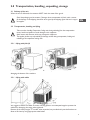
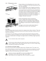
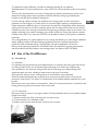
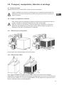
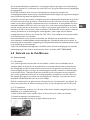
2.2 Transportation, handling and lifting
Take care when handling Evaporative Cooling units during unloading from the transportation
means, handle and position to avoid damages to the equipment.
Avoid contact with elements, which may damage the equipment.
The supplier declines any responsibility for damage caused during transportation, loading and
unloading of the evaporative cooling units.
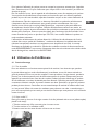
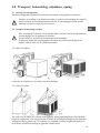
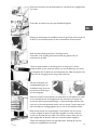
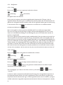
2.2.1 Lifting with fork lift
Widen the forks as much as possible to balance the load. Dip the ends of the forks to avoid
damaging the bottom of the machine.
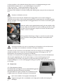
2.2.1 Lifting with cables
We suggest to attach the cables as shown, inserting spacers of an adequate length to prevent the
cables from damaging the casing when tightened.
Because of the heavy weight, TC models, when unpacked, are provided with punched brackets to
allow to lift them by using appropriate metal tubes.
!
!

6
Place the goods down with care, avoiding sudden movements or, worse, dropping the goods.
IT IS ABSOLUTELY FORBIDDEN to station under suspended loads and inside the movement area
of the lifting equipment.
When handling the units, use suitable means according the weights involved, as envisaged by EC
Directive 89/391 and subsequent amendments.
Lifting must only be carried out by qualied personnel.
2.3 Unpacking the equipment
Free items from the packaging material and collect the packaging to avoid potential danger of re and
suffocation of persons or animals.
Leave the machine on its packaging base until the installation to avoid damages.
Disposal of packaging materials must be conform to the regulations in force in the country of
destination where the evaporative cooling unit is installed.
2.4 Storage
During transportation and storage, make sure that the environmental temperature is between -10
and 50 °C. If the ColdStream evaporative cooling unit must be stored, make sure that the relative
humidity in the warehouse is between 5% and 90%.
3.0 Positioning and installation
3.1 General warnings
Before proceeding to install, make sure that each evaporative cooling unit has been unpacked and
checked for damage.
Positioning and installation of the evaporative cooling units must be carried out by qualied
personnel and by observing the laws in force in the country of destination.
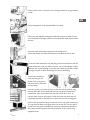
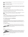
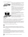
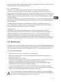
3.2 Roof installation
Prepare and x an air inlet anged duct. The ange has to be of the
same dimension of the unit’s trunk duct ange.
The unit is equipped with a trunk of anged duct that will be xed to the
ange of the inlet duct prepared before.
3.2.1 TA Evaporative coolers
Position the evaporative cooler base to the inlet duct and x the two
anges (base duct ange-inlet duct ange) together by using provided
bolts.
It is recommended to insert some silicon paste between the two
anges to guarantee perfect insulation from external agents.
!
!
!
!

7
EN
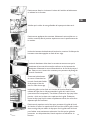
Position and x the 4 coloumns at the cooling unit base by using provided
screws.
Check the tightness of the pump exible hose clamp.
Positioning and applying cooling pads. Maintain the groove (made on one
side of the pad) in the upper position and towards the external part of the
machine.
Insert the water distribution stripes into the pad grooves.
Check that stripes are well pressed down to the bottom of their seat.
Insert the water distributor into the pad grooves and make sure that the
water distributor rests in a uniform manner over the distribution stripes.
Maintain the hose-end tting on the side of the water pump. Make a hole
through the pads to allow the passage of the hose-end tting.
Connect the distributor
hose-end tting to the
exible hose coming from
the pump and x them with
an hose clamp.
Insert the grates on the sides and rear of the unit and x them by using
the clips provided. Do not assemble the front unit grate (connections/
components side). At rst insert the clips till to their rst “click” on
the two upper corners of the grate. Finally force the clips until they are
completely inserted so that they do not protrude from the cooling pads.
Position the cap without xing it to allow the front unit grate insertioning.
The cap must be lifted so the grate slots into its seat. Do not use clips to
x the front unit grate to facilitate any necessary maintenance operation.
Once the protection grates have been positioned, x the cup by using
supplied screws.

8
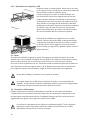
3.2.2 TC Evaporative coolers
Prepare and x an air inlet anged duct and a frame to hold
up the unit. The ange has to be of the same dimension of the
unit’s trunk duct ange.
The unit is equipped with a trunk of anged duct that will be
xed to the ange of the inlet duct prepared before and with
two side girders bars that will be xed to the prepared frame.
Verify that the frame is designed to well support the weight of
the machine, doesn’t cause vibrations and it must be perfectly
horizontal. If necessary to insert antivibration dumpers
between frame and the bars, this needs to be planned before
manufacturing the frame and consider to insert exible
couplings in the hydric connections.
Position the evaporative cooler on the inlet duct.
Fix the two anges (base duct ange-inlet duct ange)
together and the bars at the frame by using provided bolts.
We suggest to insert an outlet exible connection between
the two anges to avoid vibrations transmitted through the
ducts.
We suggest to insert silicone sealant between anges to
guarantee perfect insulation from external agents.
3.3 Notes
Inside the building, prepare the anchor points for the support chains of the air inlet duct. These must
be placed in a position to avoid excessive stress to the air inlet duct and make sure they are on the
same axis as the machine.
To anchor the unit to the ceiling or to the wall, use chains and accessories having the necessary
test certicates, made from zinc-plated steel or stainless steel and having a wire diameter of no less
than 3 mm or dimensioned for the weight to be supported, bear in mind safety margins imposed by
regulations.
Do not use aluminium alloy or similar components.
The ducts must be sized according to the ratings of the system and the characteristics of the fan.
Incorrect calculation of the size of the ducting may lead to a drop or an increase in output, causing
the activation of any safety devices in the system.
3.4 Connection to the power supply
Each unit must be connected to the power supply using an Omnipolar switch. The isolator must
have a distance between its contacts of at least 3 mm for each pole and must be placed in a position
that can be easily reached by the user. The electrical plant must be constructed according to the
regulations in force in the country where the machine is installed.
Connection to the power supply MUST be carried out by qualied personnel.
All components used to connect the power supply must be certied.
Before working on the power supply cables, make sure that power has cutted-off.
!
!
!

9
EN
Provide an efcient earth connection.
The unit is supplied with an electrical switch box for the connections, this is placed on the external
part of the unit. It contains a main power inlet switch and a domino for the remote control module
connection. The unit is supplied also with a remote control module to be installed inside the building.
For connection to the power supply, use a multipolar cable + T (earth) according to directives in
force.
Comfort line: For connection to the remote control device use shielded cable type 20 AWG - 5
poles with a minimum section of 0,50 sq. mm – Maximum length of 25 meters.
Basic line: For connection to the remote control device use multipolar cables according to directives
in force. Perform connections as shown on the wiring diagram enclosed in this manual or inside the
on-board electrical box.
It is absolutely necessary to maintain the polarity of the electrical phases and the numbers on the
wires/terminals.
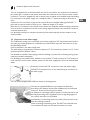
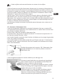
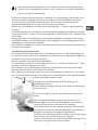
3.5 Connection to the water supply
The ColdStream cooling unit is connected to the water supply by a 3/8” sleeve attachment found on
the lower part of the equipment, it is advisable to provide a water tap at the water inlet to run dry
the plant before winter.
Insert a sand lter in the water supply plant.
The water piping must guarantee a minimum capacity of 5 -10 Lt/minute at a pressure of 1.5 - 3 bars.
(maximum pressure allowed: 6 bars).
It is advisable to install the water piping inside the building, to protect it from freezing during winter,
otherwise, insulate it adequately.
It is advisable to use potable water, hardness not more than 27°f and not less than 7°f. If hardness is
more than 30°f, insert a water softener system into the water supply plant. Don’t use demineralized
water.
Proceed to connect the 3/8” connection to the main water supply.
DO NOT use excessive force on the sleeve during its connection to
the water supply.
The unit is also equipped with a Ø60 mm sleeve to discharge water.
Connect the supplied exible hose (on request for Basic line)
according to the situation found at the installation site as mentioned
further on, x the hose by using a hose clamp.
1st Situation: If a discharge system is present, connect the tube to the
dis-charge according to the regulations in force regarding hygiene in
the country where the unit is installed.
2nd Situation: If no discharge system is present, place the hose in the
best way avoiding any bends.
When connecting the discharge hose, DO NOT use excessive force
on the sleeve and make sure that the sleeve does not rotate.

4.0 Protection devices
4.1 Protection devices
To comply with the instructions of the European Community Directives, applicable to the unit
referred to in this use and maintenance manual, Mark Climate Technology has designed the safety
systems on the unit foreseen by the regulations in force.
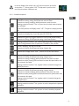
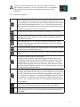
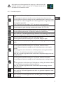
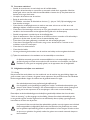
4.2 Caution signs applied on the unit
DANGER: Risk of electric shock
MOVING MACHINERY
4.3 Clothing
The equipment is destined for installation in positions which cannot be directly reached by users
during normal operations and therefore particular prescriptions regarding clothing are not necessary.
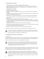
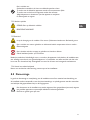
4.4 Residual risks
It is forbidden to use water to clean electro-mechanical components
Electrocution danger
Pay attention to fan movement. Do not introduce arms or limbs.
Mechanical danger
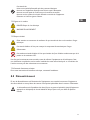
4.5 Emergency situations
In case of emergency immediately turn the machine off and cut off the electrical circuit through the
omnipolar isolator switch, identify and solve the problem, contact Mark Climate Technology.
It is absolutely forbidden to use water to put out res, use exclusively powder or CO2 extinguishers.
5.0 Functioning notes
The functioning of the evaporative cooler is based on an important principle: It introduces big
quantities of fresh air into the building and removes hot exhausted air through doors, windows and
other openings. If the system is not able to expel the air volume introduced into the building, the
efciency would be compromised. INLET FRESH AIR = OUTLET HOT AIR: a very simple principle.
If the system is able to expel all the air introduced into the building, the system operates at the
highest efciency. The ideal condition is when, into the building, the air diffusers are positioned away
(better on the opposite side) from the openings (windows, doors, etc.) so the air passes through
the building while cooling it. Maximum efciency can be reached by adjusting the dimensions of
the window and door openings. Never close the openings: if they are closed, no changes of air will
occur, consequently reducing the cooling effect and increasing the relative humidity level inside the
building.
10
!

To optimize the system efciency, consider the following openings for air expulsion:
Guarantee about 0,5 sq.mt of extraction for every 1000 cu.mt. of introduced air (refer to the project
data).
The more dry the external air is, the more cooling capacity could be reached by the system. Your
evaporative cooling system will not operate at maximum efciency during high humidity days
however it will still reach an efcient cooling level.
In areas with high relative humidity, the evaporative air cooling system must be oversized to
guarantee more air changes, or in other words, it must have higher capacity to compensate the
smaller temperature difference given. In these areas, the maximum cooling effect will be reached by
making sure that there are more air evacuation points than normally used and that the units will be
switched on early in the morning to avoid latent heat growing up inside the space to be cooled. Your
supplier will design your system considering your climatic conditions. During days when the relative
humidity level is near to or more than 70%-75%, it is advisable to switch on the system in ventilation
mode only.
The cooling efciency of a system depends on: the cooling unit efciency, air ducts design, installation
quality, building conditions. Insulated ceilings signicantly reduce the internal temperature in
comparison with uninsulated ceilings. The same latter concept is applicable to the air duct.
During normal operating conditions in COOLING mode, the evaporation process leaves mineral
salts accumulation and solid residue in the discharge water, this water is NOT POTABLE.
6.0 Use of the ColdStream
6.1 First start-up
2.1.1 All models
For optimally using and functioning of the plant/machine it is necessary that, during the rst start-up
(in cooling mode), the fan runs at minimum speed and keeps it for at least one complete day.
If this procedure is not observed, during the rst day of functioning only, malfunctioning of the
evaporative pads may occur resulting in water drops coming out of the ducts.
During the rst start-up of your cooling system, an unusual odour may be detected.
When the evaporative panels start to get wet, they may emit a particular odour, which may be
present for several hours. This odour is a characteristic of the treated cellulose material but it is not
harmful.
Even the fan motor may present a “characteristic” odour for a short period, which is caused by initial
heating and by any paint on the surface of the motor itself.
2.1.2 TC model series
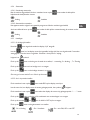
During rst start-up, be sure of the right rotation of the fan (indicated with an arrow (adhesive plate)
placed on fan body):
1. Take the machine top off by unscrewing the 4 corners screws.
2. Turn the machine on in ventilation mode
3. Rotation must have the same direction of the arrows as shown:
11
EN

12
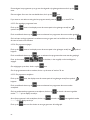
4. If the fan should rotate in the wrong direction, it’s necessary change the main switch power supply
connections by exchanging L1 and L2 connections
5. Look again... rotation has the same direction of the arrow.
6. Replace and x the machine top.
If at point 3, the fan should rotate in the right direction, go to point 6 avoiding point 4 and 5.
Check the tightness of the belt
As the latter, after the rst few hours of operation, tend to loosen due to the elasticity of the
rubber, correct tension must be restored, thus avoiding annoying noises and ensuring long life. To
check the belt, proceed as follows:
Place a perfectly straight extruded bar on the two pulleys, by using a
nger apply a light force on the middle of the belt and measure the
distance between the exed belt point and the bar. The distance should
be between 1cm and 1,5cm.
If the measured distance is higher or lower, it’s necessary to tight or to
re-lease the belt by using the apposite screw.
Excessive tightness of the belt as well as reducing the life of the belt, may also cause deformations
to the fan shaft and overload the bearings
Check, when checking the tightness of the belt, that the fan bearings do not leak liqueed grease:
this, together with the excessive temperature of the bearings (>60°C), detectable by touch, is a
symptom of defects.
Check that the power input value of the electric motor fall within the operating limits shown on the
rating plate. If the value is higher, this is normally the result of overestimating the pressure drop in
the system, and must be corrected by adjusting the equalizing dampers and/or the transmission ratio
by changing one of the two pulleys.
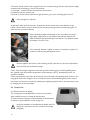
6.2 Comfort line
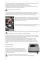
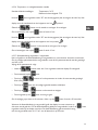
6.2.1 Remote Control Unit (display)
The cooling units are equipped with a remote control panel,
which enables the user to manage all the functions.
This panel contains a logical unit which enables several functions
necessary for good operation of the cooling unit.
At the rst installation, it’s possible that the display shows Etc
blinking. It’s necessary to set the current time (see Settings
paragraph)
!
!
!

13
EN
In case the Display of the control unit is off, make sure that the dip switch is
set to position “1” and not position “ON”. The dip switch is present on the
main e-board inside the ColdStream unit.
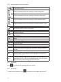
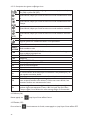
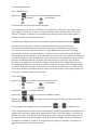
6.2.1.1 Controller descriptions
Keeping pressed more than 1”sec., switches the cooling unit on or off.
Pressed once during setting On/Off periods, exits the menu.
Pressed once during modifying default parameters, exits the menu.
Keeping pressed more than 3”sec., if control unit is locked, makes it tempo-
rary unlocked.
In the OFF position, the Display shows:” oFF ”. The panel is always powered
on.
Pressed once, displays the current fan speed (F1-F2-F3-FA).
Pressed once, gets into program selection or into On/Off periods setting.
Pressed once during On/Off periods setting, it has Enter function.
Keeping pressed more than 1”sec., selects operating mode: Cooling ON (ma-
nual), Cooling/Ventilation AUTO (automatic), Ventilation ON (manual).
If time is displaying, sets the current day.
Pressed once during On/Off periods setting, changes days.
Pressed till the display shows “time”, it shows the current time setted.
If time is displaying, sets the current hour.
Pressed once during On/Off periods setting, changes hours.
Pressed once during modifying default parameters, increases the value.
Pressed once after pressing FAN command, increases fan speed and/or disa-
bles automatic fan speed.
Keeping pressed more than 2”sec. togheter with M command, changes the
default parameters.
If time is displaying, sets the current minutes.
Pressed once during On/Off periods setting, changes minutes.
Pressed once during modifying default parameters, decreases the value.
Pressed once after pressing FAN command, decreases fan speed and/or disa-
bles automatic fan speed.
Keeping pressed more than 2”sec. togheter with H command, changes de-
fault parameters.
Pressed once, shows the temperature detected.
Keeping pressed more than 5”sec., permits to set the temperature requested
(set-point).
Pressed once, shows the humidity detected.
Keeping pressed more than 5”sec., permits to set the humidity requested
(set-point).
!

14
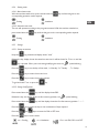
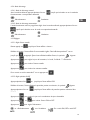
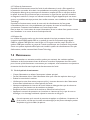
6.2.1.2 Signals descriptions and on-screen displays
The led indicates if the timer ( Automatic program) is in the On phase (ON)
or the Off phase (OFF)
When lit, indicates that the unit is working in manual cooling mode.
When lit, indicates that the unit is working in automatic cooling mode.
When lit, indicates that the unit is working in manual ventilation mode.
When lit, indicates that the unit is working in automatic ventilation mode.
day 1-7 When lit, indicates the day-of–the-week is shown: 1°= Monday …
Blinks during modifying values or parameters.
OFF Unit off. Attention: the panel is always powered-on.
FAN Ventilation mode only.
P-00
STARTING COOLING - Waits for the drain valve to close and turns the
water pump on.
P-01 COOLING
P-02 DRAIN
Cln SELF CLEANING
STOP End of program - OFF period
Loc Control unit locked
--:-- Free space in memory
- - Temperature and humidity probe disconnected
En
Communication doesn’t work properly. It’s possible a wrong connection of
the wires
EE Eeprom failure, try to turn off and turn on the unit
EA
TIME OUT lling or draining tank failure. To cancel the event, try to power
off and to power on again. If failure is still on display, it is necessary to do
maintenance the unit.
Etc
Clock error. The time on the remote controller is not set. The device sets
automatically the time to 8.10 am on Monday. Until the time is not set, the
display will show the same message. Set the current time.
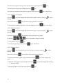
6.2.2 Switching ON
Keep key pressed until the display will shows the time
6.2.3 Switching OFF
To stop the unit functioning, keep key pressed until the display will show OFF

15
EN
6.2.4 Starting mode
6.2.4.1 Manual start mode
With the machine switched on, press several times the key until the led goes on the
corresponding operation mode required:
Cooling Ventilation
6.2.4.2 Automatic start mode
The unit will operate according to the programme setted. With the machine switched on,
press several times the key until the led goes on the corresponding mode required:
Cooling Ventilation
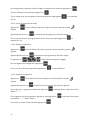
6.2.5 Settings
6.2.5.1 Setting current time
Keep the key pressed until display shows “time”
Release the key, display shows the setted current time. It will be shown for 5”sec. or until the
key is pressed. When you are showing/modifying the time, the symbol blinking.
Press the key to set the day of the week, 1 = Monday, 2 = Tuesday . . , 7 = Sunday.
Press the key to insert the current hour.
Press the key to insert the current minutes.
To get back wait 5”sec. or press the key
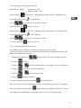
6.2.5.2 Setting On/Off periods
Press several times the key until the display shows PR9.
Release the key, the display shows the rst memory position, the symbol blinking.
Press several times the key until the display shows the rst free memory position “- -:- -“.
Press the key to insert the day or the combination of days required.
Press the and keys to insert the ON or OFF time.
Press the key to set the event:
on = Cooling on = Ventilation On = unit ON, Off = unit OFF

16
Then save the programme and go to the next free memory space press the key.
Then exit and show the preview display, press the key.
If you want to exit without saving the last program setted, press the key or wait 30”sec.
6.2.5.3 Reading a stored program
Press the key and the display will show the rst space in memory while the symbol
blinking.
Press several times the key and select the programme to be changed.
To exit programs reading and go back to the main display, press the key or wait 30”sec.
6.2.5.4 Modifying a program
Press the key and the display will show the rst space in memory while the symbol
blinking.
Press several times the key and select the programme to be changed.
By pressing keys it is possible to change the settings.
To save changes, press the key.
To exit the programming mode press the key or wait 30”sec.
6.2.5.5 Deleting a program
Press the key, the display will show the rst space in memory while the symbol
blinking.
Press several times the key and select the programme to be deleted.
To delete the selected program, press and keep pressed the key, until the display will
show “- -:- -“
To delete all the programs, press and keep pressed the key, until the display after showing
“- -:- -“ will show “EALL”.
To exit and go back to the current time, press the key.

17
EN
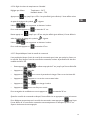
6.2.5.6 Setting temperature and humidity values
Default factory settings: Temperature : 26°C
Relative humidity : 75%
Keep pressed the key until “SP” is displayed (then release the key). The display shows
the set point value and the symbol blinking.
Use the keys to increase or decrease the value.
To conrm press the key or wait 10”sec.
Keep pressed the key until “SP “ is displayed ( then release the key). The display shows
the set point value and the symbol blinking.
Use the keys to increase or decrease the value.
To conrm press the key or wait 10”sec.
6.2.5.7 Locking/Unlocking remote control unit
It is possible to lock the remote control unit to avoid the control by anyone.
To lock the remote command unit the HL parameter value must be modied from NO to YES.
Modify the HL parameter as follows:
• Keep pressed together the keys more than 2”sec until the display shows PA.
• Press the key twice.
• Press the or keys to nd the parameter to be changed. In this case choose HL.
• Press the key to see the current setted value.
• Press the or keys to change the value.
• Press the key again to go back.
To save the modication and exit press the key or wait 30”sec.
When the remote control is locked, display shows Loc when pressing every key. To temporary
unlock the remote control, keep the key pressed until the display shows off. The remote
control goes automatically back to locked status after 15”sec. from last key pressing.

18
6.2.6 Operating mode
6.2.6.1 Cooling
Press key to choose the cooling mode desired:
(manual) (automatic)
The machine starts cooling function.
If the probe detects, inside the building, a humidity value 5% more than the value setted, the machine
goes in ventilation mode (cooling stand-by). If the probe detects, inside the building, a humidity
value less than value setted, the machine goes back in cooling mode.
It’s possible to set the air ow by choosing the fan speed by using the key.
It’s also possible to set automatic speed function FA (see next part).
To guarantee pads longer life, the evaporative cooler has the tank’s water changes every 4 hours
(factory default) and a pads self cleaning cycle when the machine is switched off:
Every 4 hours, the machine goes in cooling stand-by (ventilation mode). It drains water from its tank
and re-lls it with fresh water, then goes back in cooling mode. (Elapsing time between the tank’s
water change can be modied depending on environmental conditions and/or kind of water inlet.
To make this change, it’s necessary to call Mark Climate Technology). Every time the evaporative
cooler is switched off, it starts a pads self clearing cycle 10 minutes long. It drains water from its tank
and re-lls it with fresh water, than it starts water recirculation through the pads (ventilation off) to
remove residual salts and other kind of dirtiness. At the end of cycle the machine drains the water
from the tank.
6.2.6.2 Ventilation
Press key to choose the ventilation mode desired:
(manual) (automatic)
The machine starts ventilation function.
Press the key to display the current fan speed.
Press or keys to set the fan speed desired or the automatic speed function “AUTO”
To save the changes and exit press the or keys or wait 1”sec.
Air ow during automatic speed function (FA) depends on the setted temperature value
and the temperature value detected by the probe. If the probe detects, inside the building, a
temperature value higher than the value setted, the fan start on higher speed until it reaches the
setted temperature value. When the temperature is reached, the fan goes on lower speed. If the
temperature rises up, the fan goes on higher speed. The fan will go on as described before.

19
EN
6.2.7 Operating faults
If during normal operations of your cooling unit, the “EA” code appears on the control panel, it is
most likely that dirtiness has accumulated (e.g.: leafs, etc.) around the discharge valve and it doesn’t
allow the complete evacuation of the water or it could be the level switch that doesn’t work
properly. The error signal can be reset by turning off the machine. If, when turning back on the
machine, the signal appears again after about 1 minute, a technical problem does persist so it’s better
to contact the installer or Mark Climate Technology.
If during normal operations of your cooling unit, water drips continuously through overow holes,
it is most likely that the level switch is not working properly. Contact the installer or after sales
service.
In both cases it would be best to shutdown the plant, cut-off electrical power, close the water tap,
get in touch with the installer who constructed the plant or a licensed technical service center.
6.2.8 Bus System
Comfort line models have on-board printed circuit that allows to have a BUS System connection
called CBS or a one command control system called CABS. The CBS system can be controlled by
a P.C. and can manage up to 58 units. The CABS System can manage groups of 5 unit controlled
by one remote command. It is possible to have these systems implemented even after the cooling
system is installed. For further information, please contact Mark Climate Technology.
7.0 Maintenance
We recommend annual service to the system to maintain it in perfect operation conditions. Before
the machine start-up the equipment should be checked to make sure it will work properly, so any
maintenance or repairs necessary could be carried out before the working season of the unit.
7.1 End of season maintenance
• Cut power inlet off by using the main isolator-switch.
• Close the water supply. Empty the water supply plant to avoid bursts due to icing.
• Take the machine top off.
• Check that waterways are clean and that there are no obstructions in the water supply and
distributor in the upper part of the unit. Clean any debris in the water pump.
• Fully clean the tank of the unit. Use a mild detergent, not a solvent cause it may react with plastic
materials.
• Replace and x the machine top using the bolts supplied.
• Apply the protection cover on the machine making sure that it has no holes or damages, if
damage is detected, repair the cover or substitute it.
It is very important that the protection cover is applied to the evaporative cooler at the end of the
season, this avoids the machine from being damaged by climatic factors during the set-aside period;
smog, acid rain, ice, etc.
!

20
7.2 Pre-season maintenance
• Cut power inlet off by using the main isolator-switch.
• Remove the protection cover and check for any damage that may have occurred. Clean the
cover well with mild detergent and store it in a place where it is protected from bad weather.
• Remove the machine top.
• If necessary clean the tank.
• TC models: check the tightness of the belt (*) – (see par. 2.6.2). When damaged it must be
changed.
• Check the evaporative pads and clean them from any dirtiness using water. If they have too much
incrustation, it is necessary to change them.
• Check that waterways are clean and that there are no obstructions in the water supply and
distributor in the upper part of the unit. Clean any debris in the water pump.
• Turn the machine on by using the main isolator-switch.
• Open the water supply. Start the system in COOLING mode and check that the discharge valve
is closed and that the water lls the tank up until the water inlet valve stops.
• Check that the water is distributed evenly on all evaporative pads.
• Check that the discharge valve is working properly; make sure that it opens within 5 minutes
after having pressed the OFF key.
• Check if there are losses of water.
• Check cables conditions.
• Replace and x well the machine top using the bolts supplied.
(*) During working season, it is advisable to check it monthly.
The manufacturer does not assume any responsibility or is liable for any guarantee due to damage
caused by non-observance of prescriptions, any non-conform installations and, in the case of
improper use, of the equipment by the nal user.
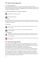
7.3 Maintenance safety regulations
7.3.1 Clothing
The personnel charged to machine maintenance must not wear clothing with large sleeves, laces
or belts, which may cause danger. The personnel must also wear individual protection devices
conforming to the laws and regulations in force.
The maintenance personnel must be professionally qualied.
Before carrying out any maintenance operations, read this section of the manual carefully. Mark
Climate Technology is not responsible for any damage or malfunctions due to lack of respect of the
indications contained in the present section of this manual.
During maintenance operations, place clearly and easily visible a sign stating “Work in Progress” on
all access areas to the department. Record all maintenance operations carried out on an appropriate
register, making sure to state: date, time, type of intervention performed and the name of the
person.
The personnel charged to maintenance that use any solvents must be equipped with individual
protection devices (safety glasses, lter masks, gloves) suitable for contact with the solvent used.
When using solvents it is strictly forbidden to smoke and use open ames. After use, ventilate the
building to help any residual vapours to leave.
!
!
!
La page est en cours de chargement...
La page est en cours de chargement...
La page est en cours de chargement...
La page est en cours de chargement...
La page est en cours de chargement...
La page est en cours de chargement...
La page est en cours de chargement...
La page est en cours de chargement...
La page est en cours de chargement...
La page est en cours de chargement...
La page est en cours de chargement...
La page est en cours de chargement...
La page est en cours de chargement...
La page est en cours de chargement...
La page est en cours de chargement...
La page est en cours de chargement...
La page est en cours de chargement...
La page est en cours de chargement...
La page est en cours de chargement...
La page est en cours de chargement...
La page est en cours de chargement...
La page est en cours de chargement...
La page est en cours de chargement...
La page est en cours de chargement...
La page est en cours de chargement...
La page est en cours de chargement...
La page est en cours de chargement...
La page est en cours de chargement...
La page est en cours de chargement...
La page est en cours de chargement...
La page est en cours de chargement...
La page est en cours de chargement...
La page est en cours de chargement...
La page est en cours de chargement...
La page est en cours de chargement...
La page est en cours de chargement...
La page est en cours de chargement...
La page est en cours de chargement...
La page est en cours de chargement...
La page est en cours de chargement...
La page est en cours de chargement...
La page est en cours de chargement...
La page est en cours de chargement...
La page est en cours de chargement...
La page est en cours de chargement...
La page est en cours de chargement...
La page est en cours de chargement...
La page est en cours de chargement...
-
 1
1
-
 2
2
-
 3
3
-
 4
4
-
 5
5
-
 6
6
-
 7
7
-
 8
8
-
 9
9
-
 10
10
-
 11
11
-
 12
12
-
 13
13
-
 14
14
-
 15
15
-
 16
16
-
 17
17
-
 18
18
-
 19
19
-
 20
20
-
 21
21
-
 22
22
-
 23
23
-
 24
24
-
 25
25
-
 26
26
-
 27
27
-
 28
28
-
 29
29
-
 30
30
-
 31
31
-
 32
32
-
 33
33
-
 34
34
-
 35
35
-
 36
36
-
 37
37
-
 38
38
-
 39
39
-
 40
40
-
 41
41
-
 42
42
-
 43
43
-
 44
44
-
 45
45
-
 46
46
-
 47
47
-
 48
48
-
 49
49
-
 50
50
-
 51
51
-
 52
52
-
 53
53
-
 54
54
-
 55
55
-
 56
56
-
 57
57
-
 58
58
-
 59
59
-
 60
60
-
 61
61
-
 62
62
-
 63
63
-
 64
64
-
 65
65
-
 66
66
-
 67
67
-
 68
68


dans d''autres langues
- English: Mark COLDSTREAM
- Nederlands: Mark COLDSTREAM
Autres documents
-
ClimateMaster Dedicated Outside Air Systems Le manuel du propriétaire
-
Wacker Neuson PT6LS Manuel utilisateur
-
SsangYong NEW CHAIRMAN Le manuel du propriétaire
-
Wacker Neuson HI900D Manuel utilisateur
-
Impecca IWA05-KR15 Mode d'emploi
-
-
-
Fujitsu AOYA72LALT Guide d'installation
-
Danfoss Application Handbook - Automatic Controls for Industrial Refrigeration Systems Mode d'emploi
-
 Seeley LCS Le manuel du propriétaire
