Maytag GFG Installation Instructions Manual
- Catégorie
- Cuisinières
- Taper
- Installation Instructions Manual

INSTALLATIONINSTRUCTIONS
30" (76.2 CM) FREESTANDINGGAS RANGES
INSTRUCTIONSD'INSTALLATIONDESCUISINIERESA GAZ
AUTOPORTANTESDE30" (76,2 CM)
TableofContents/Tabledes mah_res
RANGE SAFETY ............................................................................. 2
INSTALLATION REQUIREMENTS ............................................... 3
Tools and Parts............................................................................ 3
Location Requirements ............................................................... 3
Electrical Requirements ............................................................... 5
Gas Supply Requirements ........................................................... 5
INSTALLATION INSTRUCTIONS ................................................. 6
Unpack Range ............................................................................. 6
Install Anti-Tip Bracket ................................................................ 7
Make Gas Connection ................................................................. 8
Verify Anti-Tip Bracket Location .................................................. 9
Level Range ................................................................................. 9
Electronic Ignition System ........................................................... 9
Replace Oven Racks and Storage or Warming Drawer ........... 11
Complete Installation ................................................................. 11
GAS CONVERSIONS ................................................................... 12
LP Gas Conversion .................................................................... 12
Natural Gas Conversion ............................................................ 14
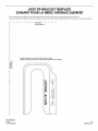
ANTI-TIP BRACKET TEMPLATE ................................................ 32
SI_CURITI_ DE LA CUISINII_RE ................................................... 16
EXIGENCES D'INSTALLATION ................................................... 17
Outillage et pieces ...................................................................... 17
Emplacement d'installation ........................................................ 17
Specifications electriques .......................................................... 19
Specifications de I'alimentation en gaz ..................................... 19
INSTRUCTIONS D'INSTALLATION ............................................ 21
Deballage de la cuisiniere .......................................................... 21
Installation de la bride antibasculement .................................... 21
Raccordement a la canalisation de gaz ..................................... 22
Verification de I'emplacement de la bride antibasculement .....23
Mise & niveau de la cuisiniere .................................................... 24
Systeme d'allumage electronique ............................................. 24
Reinstallation des grilles du four et du tiroir de
remisage ou du tiroir-rechaud ................................................... 26
Achever I'installation .................................................................. 26
CONVERSIONS POUR CHANGEMENT DE GAZ ...................... 26
Conversion de Gaz naturel & Propane ....................................... 26
Conversion de Propane &Gaz naturel ....................................... 29
GABARIT POUR LA BRIDE ANTIBASCULEMENT .................... 32
iMPORTANT:
Installer: Leave installation instructions with the homeowner.
Homeowner: Keep installation instructions for future reference.
iMPORTANT :
Installateur : Remettre les instructions d'installation au propri6taire.
Propri6taire : Conserver les instructions d'installation pour r6f6rence ult_rieure.
W10196160C

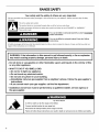
RANGESAFETY
Your safety and the safety of others are very important.
We have provided many important safety messages in this manual and on your appliance. Always read and obey all safety
messages.
This is the safety alert symbol.
This symbol alerts you to potential hazards that can kill or hurt you and others.
All safety messages will follow the safety alert symbol and either the word "DANGER" or "WARNING."
These words mean:
You can be killed or seriously injured if you don't immediately
follow instructions.
You can be killed or seriously injured if you don't follow
instructions.
All safety messages will tell you what the potential hazard is, tell you how to reduce the chance of injury, and tell you what can
happen if the instructions are not followed.
WARNING: If the information in this manual is not followed exactly, a fire or explosion
may result causing property damage, personal injury or death,
- Do not store or use gasoline or other flammable vapors and liquids in the vicinity of this
or any other appliance,
- WHAT TO DO IF YOU SMELL GAS:
• Do not try to light any appliance.
• Do not touch any electrical switch.
• Do not use any phone in your building.
• Immediately call your gas supplier from a neighbor's phone. Follow the gas supplier's
instructions.
• If you cannot reach your gas supplier, call the fire department.
- Installation and service must be performed by a qualified installer, service agency or
the gas supplier,
Tip Over Hazard
A child or adult can tip the range and be killed.
Connect anti=tip bracket to rear range foot.
Reconnect the anti=tip bracket, if the range is moved.
Failure to follow these instructions can result in death or serious burns to children and adults.
2

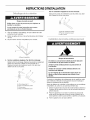
INSTALLATIONREQUIREMENTS
s c nd
Gather the required tools and parts before starting installation.
Read and follow the instructions provided with any tools listed
here.
Tools needed
• Tape measure • Marker or pencil
• Flat-blade screwdriver • Pipe-joint compound
resistant to LP gas
• Phillips screwdriver
• Level • 3/le"(4.8 mm) carbide-tipped
masonry drill bit (for
• Hand or electric drill concrete/ceramic floors)
• Hammer • Noncorrosive leak-detection
solution
• Wrench or pliers
• Pipe wrench For LP/Natural Gas
Conversions
• 18/le"combination wrench • 1/2"combination wrench
• 1¼,,drive ratchet • 8/8"combination wrench
• 3/8"nut driver • 8/le"nut driver
• 1/8"(3.2 mm) drill bit (for • Quadrex ®tor Phillips
wood floors) screwdriver
• Masking tape
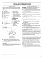
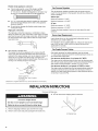
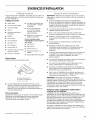
Parts supplied
Check that all parts are included.
A
C
A.Anti-tip bracket
B. Plastic anchors (2)
C. #10 x 1/=.screws (2)
Anti-tip bracket must be securely mounted to subfloor.
Thickness of flooring may require longer screws to anchor
bracket to subfloor. Longer screws are available from your
local hardware store.
Parts needed
Check local codes and consult gas supplier. Check existing gas
supply and electrical supply. See "Electrical Requirements" and
"Gas Supply Requirements" sections.
IMPORTANT: Observe all governing codes and ordinances. Do
not obstruct flow of combustion and ventilation air.
• It is the installer's responsibility to comply with installation
clearances specified on the model/serial rating plate. The
model/serial rating plate is located on the oven frame behind
the storage drawer panel.
The range should be located for convenient use in the
kitchen.
Recessed installations must provide complete enclosure of
the sides and rear of the range.
All openings in the wall or floor where range is to be installed
must be sealed.
Do not seal the range to the side cabinets.
Cabinet opening dimensions that are shown must be used.
Given dimensions are minimum clearances.
The floor anti-tip bracket must be installed. To install the anti-
tip bracket shipped with the range, see "Install Anti-Tip
Bracket" section.
• Grounded electrical supply is required. See "Electrical
Requirements" section.
• Proper gas supply connection must be available. See "Gas
Supply Requirements" section.
• Contact a qualified floor covering installer to check that the
floor covering can withstand at least 200°F (93°C).
• Use an insulated pad or 1A"(0.64 cm) plywood under range if
installing range over carpeting.
IMPORTANT: To avoid damage to your cabinets, check with your
builder or cabinet supplier to make sure that the materials used
will not discolor, delaminate or sustain other damage. This oven
has been designed in accordance with the requirements of UL
and CSA International and complies with the maximum allowable
wood cabinet temperatures of 194°F (90°C).
Mobile Home - Additional Installation Requirements
The installation of this range must conform to the Manufactured
Home Construction and Safety Standard, Title 24 CFR, Part 3280
(formerly the Federal Standard for Mobile Home Construction
and Safety, Title 24, HUD Part 280). When such standard is not
applicable, use the Standard for Manufactured Home
Installations, ANSI A225.1/NFPA 501A or with local codes.
In Canada, the installation of this range must conform with the
current standards CAN/CSA-A240-1atest edition, or with local
codes.
Mobile home installations require:
• When this range is installed in a mobile home, it must be
secured to the floor during transit. Any method of securing
the range is adequate as long as it conforms to the standards
listed above.
1-@QUADREX is a registered trademark of NLW Holdings, Inc.

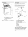
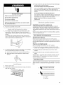
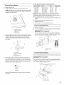
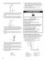
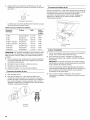
Product Dimensions
A
B C
E
A. 2T%_" (69.9 cm) max. depth with handle
B. 36" (91.4 cm) cooktop height (max.) with leveling
legs screwed all the way in*
C. 467/8" (119.1 cm) overall height (max.) with
levering legs screwed all the way in*
D. 29%" (75.9 cm) width
E. 25" (63.5 cm)
*Range can be raised approximately 1" (2.5 cm) by adjusting the
leveling legs.
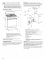
Cabinet Dimensions
Cabinet opening dimensions shown are for 25" (64.0 cm)
countertop depth, 24" (61.0 cm) base cabinet depth and
36" (91.4 cm) countertop height.
IMPORTANT: If installing a range hood or microwave hood
combination above the range, follow the range hood or
microwave hood combination installation instructions for
dimensional clearances above the cooktop surface.
A. 18" (45.7 cm) upper side cabinet to countertop
B. 13" (33 cm) max. upper cabinet depth
C. 30" (76.2 cm) min. opening width
D. For minimum clearance to top of cooktop, see NOTE*.
E. 30%" (76.5 cm) min. opening width
F. This shaded area recommended for installation of rigid gas
pipe.
G. 8" (20.3 cm)
H. Grounded outlet
I. 17" (43.2 cm)
2.2" (5.1 cm)
K. 41/_'' (11.4 cm)
L. 2" (5.1 cm) min. clearance from both sides of range to side
wall or other combustible material.
*NOTE: 24" (61.0 cm) minimum when bottom of wood or metal
cabinet is covered by not less than 1/4"(0.64 cm) flame retardant
millboard covered with not less than No. 28 MSG sheet steel,
0.015" (0.4 mm) stainless steel, 0.024" (0.6 mm) aluminum or
0.020" (0.5 mm) copper.
30" (76.2 cm) minimum clearance between the top of the
cooking platform and the bottom of an uncovered wood or metal
cabinet.

Electrical Shock Hazard
Plug into a grounded 3 prong outlet.
Do not remove ground prong.
Do not use an adapter.
Do not use an extension cord.
Failure to follow these instructions can result in death,
fire, or electrical shock.
IMPORTANT: The range must be electrically grounded in
accordance with local codes and ordinances, or in the absence
of local codes, with the National Electrical Code, ANSI/NFPA 70
or Canadian Electrical Code, CSA C22.1.
This range is equipped with an electronic ignition system that will
not operate if plugged into an outlet that is not properly polarized.
If codes permit and a separate ground wire is used, it is
recommended that a qualified electrical installer determine that
the ground path is adequate.
A copy of the above code standards can be obtained from:
National Fire Protection Association
One Batterymarch Park
Quincy, MA 02269
CSA International
8501 East Pleasant Valley Road
Cleveland, OH 44131-5575
• A 120 volt, 60 Hz., AC only, 15-amp fused, electrical circuit is
required. A time-delay fuse or circuit breaker is also
recommended. It is recommended that a separate circuit
serving only this range be provided.
• Electronic ignition systems operate within wide voltage limits,
but proper grounding and polarity are necessary. Check that
the outlet provides 120-volt power and is correctly grounded.
• The wiring diagram is located on the underside of the storage
drawer or below the warming drawer in a clear plastic bag.
NOTE: The metal chassis of the range must be grounded in
order for the control panel to work. If the metal chassis of the
range is not grounded, no keypads will operate. Check with a
qualified electrician if you are in doubt as to whether the
metal chassis of the range is grounded.
Explosion Hazard
Use a new CSA International approved gas supply line.
Install a shut=off valve.
Securely tighten all gas connections.
if connected to LP, have a qualified person make sure
gas pressure does not exceed 14" (36 cm) water
column.
Examples of a qualified person include:
licensed heating personnel,
authorized gas company personnel, and
authorized service personnel.
Failure to do so can result in death, explosion, or fire.
Observe all governing codes and ordinances.
IMPORTANT: This installation must conform with all local codes
and ordinances. In the absence of local codes, installation must
conform with American National Standard, National Fuel Gas
Code ANSI Z223.1 - latest edition or CAN/CGA B149 - latest
edition.
IMPORTANT: Leak testing of the range must be conducted
according to the manufacturer's instructions.
Type of Gas
Natural gas:
This range is design-certified by CSA International for use with
Natural gas or, after proper conversion, for use with LP gas.
• This range is factory set for use with Natural gas. See "Gas
Conversions" section. The model/serial rating plate located
behind the storage drawer on the right-hand side oven door
frame has information on the types of gas that can be used. If
the types of gas listed do not include the type of gas
available, check with the local gas supplier.
LP gas conversion:
Conversion must be done by a qualified service technician.
No attempt shall be made to convert the appliance from the gas
specified on the model/serial rating plate for use with a different
gas without consulting the serving gas supplier. See "Gas
Conversions" section.
Gas Supply Line
• Provide a gas supply line of 3_,,(1.9 cm) rigid pipe to the
range location. A smaller size pipe on longer runs may result
in insufficient gas supply. With LP gas, piping or tubing size
can be _/_"(1.3 cm) minimum. Usually, LP gas suppliers
determine the size and materials used in the system.
NOTE: Pipe-joint compounds that resist the action of LP gas
must be used. Do not use TEFLON ®ttape.

Flexible metal appliance connector:
If local codes permit, a new CSA design-certified,
4 to 5 ft (122 to 152.4 cm) long, 1/2"(1.3 cm) or
3_,,(1.9 cm) I.D., flexible metal appliance connector may
be used for connecting range to the gas supply line.
• A 1/2"(1.3 cm) male pipe thread is needed for connection
to the female pipe threads of the inlet to the appliance
pressure regulator.
• Do not kink or damage the flexible metal tubing when
moving the range.
Rigid pipe connection:
The rigid pipe connection requires a combination of pipe
fittings to obtain an in-line connection to the range. The rigid
pipe must be level with the range connection. All strains must
be removed from the supply and fuel lines so range will be
level and in line.
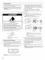
Must include a shutoff valve:
The supply line must be equipped with a manual shutoff
valve. This valve should be located in the same room but
external to the range opening, such as an adjacent cabinet. It
should be in a location that allows ease of opening and
closing. Do not block access to shutoff valve. The valve is for
turning on or shutting off gas to the range.
B
A. Gas supply line
B. Shutoff valve "open" position
C. To range
t®TEFLON isa registeredtrademark of E.I.Du Pont De Nemours andCompany.
Gas Pressure Regulator
The gas pressure regulator supplied with this range must be
used. The inlet pressure to the regulator should be as follows for
proper operation:
Natural gas:
Minimum pressure: 5" WCP
Maximum pressure: 14" WCP
LP gas:
Minimum pressure: 11" WCP
Maximum pressure: 14" WCP
Contact local gas supplier if you are not sure about the inlet
pressure.
Burner Input Requirements
Input ratings shown on the model/serial rating plate are for
elevations up to 2,000 ft (609.6 m).
For elevations above 2,000 ft (609.6 m), ratings are reduced at a
rate of 4% for each 1,000 ft (304.8 m) above sea level (not
applicable for Canada).
Gas Supply Pressure Testing
Gas supply pressure for testing regulator must be at least
1" water column pressure above the manifold pressure shown on
the model/serial rating plate.
Line pressure testing above 1/2psi gauge (14" WCP)
The range and its individual shutoff valve must be disconnected
from the gas supply piping system during any pressure testing of
that system at test pressures in excess of 1/2psi (3.5 kPa).
Line pressure testing at 1/2psi gauge (14" WCP) or lower
The range must be isolated from the gas supply piping system by
closing its individual manual shutoff valve during any pressure
testing of the gas supply piping system at test pressures equal to
or less than 1/2psi (3.5 kPa).
INSTALLATIONINSTRUCTIONS
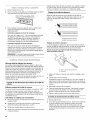
Unpc c <FScsnc, e
3. Do not remove the shipping base at this time.
Excessive Weight Hazard _
Use two or more people to move and install range.
Failure to do so can result in back or other injury.
A .................................
1. Remove shipping materials, tape and film from range.
2. Remove oven racks and parts package from inside oven.
A. Shipping base
6

4=
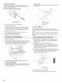
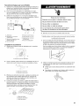
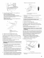
On Ranges Equipped with Storage Drawers:
Remove the storage drawer. Use a ¼" drive ratchet to lower
the rear leveling legs one-half turn. Use a wrench or pliers to
lower front leveling legs one-half turn.
A
D
C
B
A. ¼" drive ratchet
B. Rear leveling leg
C. Wrench or priers
D. Front levering leg
On Ranges Equipped with Warming Drawers:
Use wrench or pliers to lower the front and rear leveling legs
one-half turn.
A B
C
4=
5=
If countertop is not flush with cabinet opening edge, align
template with overhang.
If cabinet opening is wider than that specified in the "Location
Requirements" section, adjust template so range will be
centered in cabinet opening.
To mount anti-tip bracket to wood floor, drill two 1/8"(3.2 mm)
holes at the positions marked on the bracket template.
Remove template from floor.
A. Rear levering leg
B. Front leveling leg
C. Wrench or priers
Tip Over Hazard
A child or adult can tip the range and be killed.
Connect anti=tip bracket to rear range foot.
Reconnect the anti=tip bracket, if the range is moved.
Failure to follow these instructions can result in death
or serious burns to children and adults.
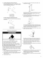
6=
7=
8=
To mount anti-tip bracket to concrete or ceramic floor, use a
3/le"(4.8 mm) masonry drill bit to drill 2 holes at the positions
marked on the bracket template. Remove template from floor.
Tap plastic anchors into holes with a hammer.
Align anti-tip bracket holes with holes in floor. Fasten anti-tip
bracket with screws provided.
Depending on the thickness of your flooring, longer screws
may be necessary to anchor the bracket to the subfloor.
Longer screws are available from your local hardware store.
Move range close enough to opening to allow for final
electrical connection. Remove shipping base, cardboard or
hardboard from under range.
Move range into its final location making sure rear leveling leg
slides into anti-tip bracket.
Contact a qualified floor covering installer for the best procedure
for drilling mounting holes through your type of floor covering.
Before moving range, slide range onto shipping base, cardboard
or hardboard.
1. Remove template from the anti-tip bracket kit (found inside
the oven cavity) or from the back of this manual.
2. Place template on the floor in cabinet opening so that the left
edge is against cabinet and top edge is against rear wall,
molding or cabinet.
3. Tape template into place.
9. If installing the range in a mobile home, you must secure the
range to the floor. Any method of securing the range is
adequate as long as it conforms to the standards in the
"Location Requirements" section.
10. Continue installing your range using the following installation
instructions.

Explosion Hazard
Use a new CSA international approved gas supply line.
install a shut=off valve.
Securely tighten all gas connections.
if connected to LP, have a qualified person make sure
gas pressure does not exceed 14" (36 cm) water
column.
Examples of a qualified person include:
licensed heating personnel,
authorized gas company personnel, and
authorized service personnel.
Failure to do so can result in death, explosion, or fire.
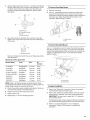
Typical rigid pipe connection
A combination of pipe fittings must be used to connect the range
to the existing gas line. Your connections may be different,
according to the supply line type, size and location.
1. Apply pipe-joint compound made for use with LP gas to all
pipe thread connections.
2. Using a pipe wrench to tighten, connect the gas supply to the
range.
{_ ,,,-_D
A F
G
A. Gas pressure regulator
B. 90 ° elbow (must have
Y2"male pipe thread)
C. Nipple
D. Union
E. Black iron pipe
F Manual gas shutoff valve
G. Y2"or 3/4"gas pipe
H. Nipple
I. Union
J. 90° elbow
Typical flexible connection
1. Apply pipe-joint compound made for use with LP gas to the
smaller thread ends of the flexible connector adapters (see B
and G in following illustration).
2. Attach one adapter to the gas pressure regulator and the
other adapter to the gas shutoff valve. Tighten both adapters.
3. Use a lS/le"combination wrench and channel lock pliers to
attach the flexible connector to the adapters. Check that
connector is not kinked.
A B C
D
E
H G F
A. Gas pressure regulator
B. Use pipe-joint compound.
C. Adapter (must have Y2"male
pipe thread)
D. Flexible connector
E.Manual gas shutoff valve
F Y2"or 3/4"gas pipe
G. Use pipe-joint compound.
H. Adapter
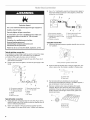
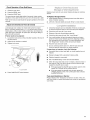
Complete Connection
1. Check that the gas pressure regulator shutoff valve is in the
"on" position.
A. Gas pressure regulator shutoff valve
2. Open the manual shutoff valve in the gas supply line. The
valve is open when the handle is parallel to the gas pipe.
3=
4.
A. Closed valve
B. Open valve
Test all connections by brushing on an approved
noncorrosive leak-detection solution. If bubbles appear, a
leak is indicated. Correct any leak found.
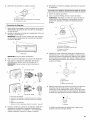
Remove cooktop burner caps and grates from parts
package. Burner caps should be level when properly
positioned. If burner caps are not properly positioned,
surface burners will not light. Place burner grates over
burners and caps.
A..........
A. Burner base
B. Burner cap
C. Burner grate
8

Electrical Shock Hazard
Plug into a grounded 3 prong outlet.
Do not remove ground prong.
Do not use an adapter.
Do not use an extension cord.
Failure to follow these instructions can result in death,
fire, or electrical shock.
5. Plug into a grounded 3 prong outlet.
1=
2.
1=
2.
On models with a storage drawer, pull drawer open to first
stop position. Lift front of drawer to clear white wheels in
drawer guides. Remove drawer and set it aside on a covered
surface.
On models with a warming drawer, the rear leg cannot be
seen by removing the warming drawer. It will be necessary to
view the rear foot from outside the range.
To check that the anti-tip bracket is installed, use a flashlight
and look underneath the bottom of the range.
• Look for the anti-tip bracket securely attached to floor.
• Slide range back so rear range foot is under anti-tip
bracket.
L
Place a rack in oven.
Place level on rack and check levelness of range, first side to
side; then front to back.
3.
If range is not level, pull range forward until rear leveling leg is
removed from the anti-tip bracket.
On Ranges Equipped with Storage Drawers:
Use a 1¼,,drive ratchet, wrench or pliers to adjust leveling legs
up or down until the range is level. Push range back into
position. Check that rear leveling leg is engaged inthe anti-tip
bracket.
On Ranges Equipped with Warming Drawers:
Use a wrench or pliers to adjust leveling legs up or down until
the range is level. Push range back into position. Check that
rear leveling leg is engaged in the anti-tip bracket.
NOTE: Range must be level for satisfactory baking
performance.
Initial lighting and gas flame adjustments
Cooktop and oven burners use electronic igniters in place of
standing pilots. When the cooktop control knob is turned to the
"LITE" position, the system creates a spark to light the burner.
This sparking continues, as long as the control knob is turned to
"LITE."
When the oven control is turned to the desired setting, sparking
occurs and ignites the gas.
Check Operation of Cool(top Burners
Standard Surface Burners
Push in and turn each control knob to the "LITE" position.
The flame should light within 4 seconds. The first time a burner is
lit it may take longer than 4 seconds to light because of air in the
gas line.
If burners do not light properly:
• Turn cooktop control knob to the "OFF" position.
• Check that the range is plugged in. Check that the circuit
breaker has not tripped or the household fuse has not blown.
• Check that the gas shutoff valves are set to the "open"
position.
• Check that burner caps are properly positioned on burner
bases.
Repeat start-up. If a burner does not light at this point, turn the
control knobs to "Off" and contact your dealer or authorized
service company for assistance.
Adjust Flame Height
Adjust the height of top burner flames. The cooktop "low" burner
flame should be a steady blue flame approximately 1¼.(0.64 cm)
high.
A _ ___5q3-
/
B
Lrd Lrd Lr'd Lrd Lr'd Lrd
A. Low flame
B. High flame

To adjust standard burner:
The flame can be adjusted using the adjustment screw in the
center of the valve stem. The valve stem is located directly
underneath the control knob.
If the "low" flame needs to be adjusted:
A. Control knob stem
B. Screwdriver
1. Light 1 burner and turn to lowest setting.
2. Remove the control knob.
Hold the knob stem with a pair of pliers. Use a small flat-
blade screwdriver to turn the screw located in the center of
the control knob stem until the flame is the proper size.
3. Replace the control knob.
4. Test the flame by turning the control from "LO" to "HI,"
checking the flame at each setting.
5. Repeat above steps for each burner.
Check Operation of Oven Bake Burner
1. Remove the oven rack.
2. To remove the oven bottom: Remove 2 screws at the rear of
the oven bottom. Lift the rear of the oven bottom up and back
until the front of the panel is away from the front frame.
Remove from oven and place on a covered surface.
A. Screws
3=
You can check the burner flame by removing the flame
spreader or by using a mirror.
Remove flame spreader:
Remove 2 screws from the front tabs of the flame spreader.
Lift front of the flame spreader and pull forward to remove
tabs from rear of oven.
Using a mirror:
Insert a mirror to one side of the burner. Look into the mirror
to check flame.
JJ
A.Mirror
B.Flame spreader
C.Flame reflection
D.2 screws
4. Push the BAKE pad.
5. Press the START pad.
The oven bake burner should light within 8 seconds. Under
certain conditions it may take the burner up to 50 to 60 seconds
to light.
Electronic igniters are used to light the bake and broil burners.
Refer to the Use and Care Guide for proper operation of the oven
controls.
Adjust Oven Bake Burner Flame (if needed)
1. On models with awarming drawer, remove access cover
plate (1 screw) located at the back of the warming drawer
compartment.
2. Check the oven bake burner for proper flame.
This flame should have a 1/2"(1.3 cm) long inner cone of
bluish-green, with an outer mantle of dark blue, and should
be clean and soft in character. No yellow tips, blowing or
lifting of flame should occur.
3. If the oven bake flame needs to be adjusted, locate the air
shutter near the center rear of the range. Loosen the locking
screw and rotate the air shutter until the proper flame
appears. Tighten locking screw.
4=
5.
J
A.Air shutter
B.Locking screw
Push CANCEL/OFF when finished.
Reinstall flame spreader and oven bake burner cover.
10

Check Operation of Oven Broil Burner
1. Close the oven door.
2. Press the BROIL pad.
3. Press the START pad.
The oven burner should light within 8 seconds. Under certain
conditions it may take the burner up to 50 to 60 seconds to light.
Refer to the Use and Care Guide for proper operation of the oven
controls.
Adjust Oven Broil Burner Flame (if needed)
Look through oven window to check broil burner for proper
flame. This flame should have a 1/2"(1.3 cm) long inner cone of
bluish-green, with an outer mantle of dark blue, and should be
clean and soft in character. No yellow tips, blowing or lifting of
flame should be present.
If flame needs to be adjusted:
1. Loosen the lock screw on the air shutter located at the rear of
the broil burner.
2. Adjust the air shutter as needed.
3. Tighten lock screw.
t
A.Lock screw
4. Press CANCEL/OFF when finished.
: ep<sce Ore t ! c scks stc d
Replace oven racks in oven cavity. Replace storage or warming
drawer.
To Replace Storage Drawer:
1. Insert storage drawer or warming drawer into slide rails on
sides of drawer opening.
2. Lift front of drawer slightly and push firmly to close drawer.
1. Check that all parts are now installed. If there is an extra part,
go back through the steps to see which step was skipped.
2. Check that you have all of your tools.
3. Dispose of/recycle all packaging materials.
4. Check that the range is level. See "Level Range."
5. Use a mild solution of liquid household cleaner and warm
water to remove waxy residue caused by shipping material.
Dry thoroughly with a soft cloth. For more information, see
the "Range Care" section of the Use and Care Guide.
6. Read the Use and Care Guide.
7. Turn on surface burners and oven. See the Use and Care
Guide for specific instruction on range operation.
If range does not operate, check the following:
• Household fuse is intact and tight, or circuit breaker has not
tripped.
• Range is plugged into a grounded 3 prong outlet.
• Electrical supply is connected.
• See "Troubleshooting" in the Use and Care Guide.
8. When the range has been on for 5 minutes, check for heat. If
the range is cold, turn off the range and check that the gas
supply line shutoff valve is open.
• If the gas supply line shutoff valve is closed, open it, then
repeat the 5-minute test as outlined above.
• If the gas supply line shutoff valve is open, press the
CANCEL button on the oven control panel and contact a
qualified technician.
If you need Assistance or Service:
Please reference the "Assistance or Service" section of the Use
and Care Guide or contact the dealer from whom you purchased
your range.
11

GAS CONVERSIONS
Gas conversions from Natural gas to LP gas or from LP gas to
Natural gas must be done by a qualified installer.
Explosion Hazard
Use a new CSA International approved gas supply line.
Install a shut-off valve.
Securely tighten all gas connections.
if connected to LP, have a qualified person make sure
gas pressure does not exceed 14" (36 cm) water
column.
Examples of a qualified person include:
licensed heating personnel,
authorized gas company personnel, and
authorized service personnel.
Failure to do so can result in death, explosion, or fire.
1,
2.
Tip Over Hazard
A child or adult can tip the range and be killed.
Connect anti=tip bracket to rear range foot.
Reconnect the anti=tip bracket, if the range is moved.
Failure to follow these instructions can result in death
or serious burns to children and adults.
Turn the manual shutoff valve to the closed position.
Unplug range or disconnect power.
...................B
A_
A. To range
B. Manual shutoff valve "closed" position
C. Gas supply line
To Convert Gas Pressure Regulator
1. Remove storage drawer or warming drawer. See "Replace
Oven Racks and Storage or Warming Drawer" section.
2. Locate gas pressure regulator at rear of storage or warming
drawer compartment.
NOTE: On models with a warming drawer, an access cover
must be removed from the gas pressure regulator.
A,
A. Gas pressure regulator
3,
4.
IMPORTANT: Do not remove the gas pressure regulator.
Remove plastic cover from gas pressure regulator cap.
Turn gas pressure regulator cap counterclockwise with a
5/8"combination wrench to remove.
NOTE: Do not remove the spring beneath the cap.
B
F
Side view before
F
C Side view after
A. Plastic cover
B. Gas pressure regulator cap with solid end facing out
C. Gas pressure regulator cap with hollow end facing out
D. Washer
E. Gas pressure regulator cap
F. Gas regulator shutoff valve (shown in the "open" position)
5. Turn over the gas pressure regulator cap and reinstall on
regulator so that the hollow end faces out and the marking
"<- LP" is facing the direction shown in the above drawing.
6. Replace plastic cover over gas pressure regulator cap.
12

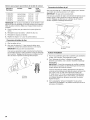
To Convert Surface Burners
1. Remove burner cap.
2. Using a Phillips screwdriver, remove the burner base.
NOTE: Reinstall one of the screws through the range cooktop
to hold the orifice spud holder in place while removing and
replacing the orifice spuds.
B
3,
A. Igniter electrode
B. Gas tube opening
C. Burner cap
D. Burner base
Apply masking tape to the end of a5/le"nut driver to help hold
the gas orifice spud in the nut driver while changing it. Press
nut driver down onto the gas orifice spud and remove by
turning it counterclockwise and lifting out. Set gas orifice
spud aside.
A
D
LP Gas Orifice Spud Chart for Surface Burners
Burner Rating Color Size ID Number
14,000 BTU Yellow/Orange 1.07 mm L107
11,000 BTU Yellow/Brown 0.99 mm L99
8,000 BTU Yellow/Black 0.85 mm L85
5,000 BTU Yellow/White 0.70 mm L70
NOTE: Refer to the Model Number and Serial Number Plate
located behind the left side of the storage or warming drawer for
proper sizing of spuds for each burner location.
5. Place Natural gas orifice spuds in the cardboard orifice spud
holder.
6. Replace the burner base using both screw.
7. Replace burner cap.
8. Repeat steps 1-7 for the remaining burners.
To Convert Oven Bake Burner
1. Remove oven racks.
2. Use a 1/2"combination wrench to turn the orifice hood down
snug onto pin (about 2 to 21/2turns).
IMPORTANT: Do not overtighten.
The oven bake burner flame cannot be properly adjusted if
this conversion is not made. See "Adjust Oven Bake Burner
Flame" in the "Electronic Ignition System" section.
A. Orifice hood
B. Pin
4,
A. Orifice spud
B. Orifice spud holder
C. Screw
D. Spark electrode
Remove the cardboard orifice spud holder located on the
back of the range near the gas inlet. Gas orifice spuds are
stamped with a number, marked with 1 color dot, and have a
groove in the hex area. Replace the Natural gas orifice spud
with the correct LP gas orifice spud.
To Convert Oven Broil Burner
Use a 1/2"combination wrench to turn the orifice hood down snug
onto the pin (about 2 to 21/2turns).
IMPORTANT: Do not overtighten.
The oven broil burner flame cannot be properly adjusted if this
conversion is not made. See "Adjust Oven Broil Burner Flame" in
the "Electronic Ignition System" section.
A. Groove
Refer to the following chart for correct LP gas orifice spud
placement.
/
/
/
A. Lock screw
B. Orifice hood
13

Complete Installation
1=
2.
Refer to the "Make Gas Connection" section for properly
connecting the range to the gas supply.
Refer to the "Electronic Ignition System" section for proper
burner ignition, operation, and burner flame adjustments.
IMPORTANT: You may have to adjust the "LO" setting for
each cooktop burner.
3=
Checking for proper cooktop, bake and broil burner flame is
very important. The small inner cone should have a very
distinct blue flame 1¼,,(0.64 cm) to 1/2"(1.3 cm) long. The
outer cone is not as distinct as the inner cone. LP gas flames
have a slightly yellow tip.
Refer to "Complete Installation" in the "Installation
Instructions" section of this manual to complete this
procedure.
Tip Over Hazard
A child or adult can tip the range and be killed.
Connect anti=tip bracket to rear range foot.
Reconnect the anti=tip bracket, if the range is moved.
Failure to follow these instructions can result in death
or serious burns to children and adults.
1=
2.
Turn the manual shutoff valve to the closed position.
Unplug range or disconnect power.
...................B
J ................ .....................C
A. Torange
B.Manual shutoff valve "closed" position
C.Gas supply fine
To Convert Gas Pressure Regulator
1. Remove storage drawer or warming drawer. See "Replace
Oven Racks and Storage or Warming Drawer" section.
2. Locate gas pressure regulator at rear of storage or warming
drawer compartment.
NOTE: On models with a warming drawer, an access cover
must be removed from the gas pressure regulator.
3=
4.
Remove plastic cover from gas pressure regulator cap.
Turn gas pressure regulator cap counterclockwise with a
%" combination wrench to remove.
NOTE: Do not remove the spring beneath the cap.
F
Side view before
A
B F
C
Side view after
A. Plastic cover
B. Gas pressure regulator cap with hollow end facing out
C. Gas pressure regulator cap with solid end facing out
D. Washer
E. Gas pressure regulator cap
F. Gas regulator shutoff valve (shown in the "open" position)
5. Turn over the gas pressure regulator cap and reinstall on
regulator so that the solid end faces out and the marking
"<- N" is facing the direction shown in the above drawing.
6. Replace plastic cover over gas pressure regulator cap.
To Convert Surface Burners
1. Remove burner cap.
2. Using a Phillips or Quadrex ®screwdriver, remove the burner
base.
NOTE: Reinstall one of the screws through the range cooktop
to hold the orifice spud holder in place while removing and
replacing the orifice spuds.
A. Gas pressure regulator
IMPORTANT: Do not remove the gas pressure regulator.
14

3,
Apply masking tape to the end of a%e" nut driver to help hold
the gas orifice spud in the nut driver while changing it. Press
nut driver down onto the gas orifice spud and remove by
turning it counterclockwise and lifting out. Set gas orifice
spud aside.
A
D
To Convert Oven Bake Burner
1. Remove oven racks.
2. Use a 1/2"combination wrench to loosen the orifice hood
away from the pin (about 2 to 21/2turns). The oven bake
burner flame cannot be properly adjusted if this conversion is
not made. See "Adjust Oven Bake Burner Flame" in the
"Electronic Ignition System" section.
A. Orifice spud
B. Orifice spud holder
C. Screw
D. Spark electrode
4,
Gas orifice spuds are stamped with a number on the side.
Replace the LP gas orifice spud with the correct Natural gas
orifice spud.
f-J- _.
db /
_:_j:Y
A. Stamped number
Refer to the following chart for the correct Natural gas orifice
spud placement.
Natural Gas Orifice Spud Chart
Burner Rating Color Size ID
Number
17,000 BTU Red/Magenta 2.10 mm N210
15,500 BTU Red/Black 2.00 mm N200
14,200 BTU Red/Orange 1.90 mm N190
13,000/13,500 BTU Red/Blue 1.85 mm N185
12,000/12,500 BTU Red/Yellow 1.80 mm N180
9,500 BTU Red/Brown 1.55 mm N155
8,000 BTU Red/White 1.40 mm N140
5,000 BTU Red/Brass 1.10 mm N110
NOTE: Refer to the Model Number and Serial Number Plate
located behind the left side of the storage or warming drawer for
proper sizing of spuds for each burner location.
5. Place LP gas orifice spuds in plastic parts bag for future use
and keep with package containing literature.
6. Replace the burner base using both screws.
7. Replace burner cap.
8. Repeat steps 1-7 for the remaining burners.
A
jl
A. Orifice hood
B. Pin
To Convert Oven Broil Burner
Use a 1/2"combination wrench to loosen the orifice hood away
from the pin (about 2 to 21/2turns). The oven broil burner flame
cannot be properly adjusted if this conversion is not made. See
"Adjust Oven Broil Burner Flame" in the "Electronic Ignition
System" section.
A. Lock screw
B. Orifice hood
Complete Installation
1. Refer to the "Make Gas Connection" section for properly
connecting the range to the gas supply.
2. Refer to the "Electronic Ignition System" section for proper
burner ignition, operation, and burner flame adjustments.
IMPORTANT: You may have to adjust the "LO" setting for
each cooktop burner.
Checking for proper cooktop, bake and broil burner flame is
very important. Natural gas flames do not have yellow tips.
3. Refer to "Complete Installation" in the "Installation
Instructions" section of this manual to complete this
procedure.
15

SECURITEDELACUISINIERE
Votre securite et celle des autres est tres importante.
Nous donnons de nombreux messages de s_curit_ importants dans ce manuel et sur votre appareil m_nager. Assurez-vous de
toujours lire tousles messages de s_curit_ et de vous y conformer.
Voici le symbole d'alerte de s_curit&
Ce symbole d'alerte de s_curit_ vous signale les dangers potentiels de d_c_s et de blessures graves & vous
et & d'autres.
Tousles messages de s_curit_ suivront le symbole d'alerte de s_curit_ et le mot "DANGER" ou
"AVERTISSEMENT". Ces mots signifient •
Risque possible de d_cbs ou de blessure grave si vous ne
suivez pas imm_diatement les instructions.
Risque possible de d_cbs ou de blessure grave si vous
ne suivez pas les instructions.
Tousles messages de s_curit_ vous diront quel est le danger potentiel et vous disent comment r_duire le risque de blessure et
ce qui peut se produire en cas de non-respect des instructions.
AVERTISSEMENT • Si les renseignements dans ce manuel ne sont pas exactement
observes, un incendie ou une explosion peut survenir, causant des dommages au
produit, des blessures ou un deces.
- Ne pas entreposer ni utiliser de I'essence ou d'autres vapeurs ou liquides inflammables
proximite de cet appareil ou de tout autre appareil electromenager.
-QUE FAIRE DANS LE CAS D'UNE ODEUR DE GAZ :
• Ne pas tenter d'allumer un appareil.
• Ne pas toucher a un commutateur electrique.
• Ne pas utiliser le telephone se trouvant sur les lieux.
• Appeler immediatement le fournisseur de gaz a partir du telephone d'un voisin. Suivre
ses instructions.
• .&.defaut de joindre votre fournisseur de gaz, appeler les pompiers.
- L'installation et rentretien doivent _tre effectues par un installateur qualifie, une agence
de service ou le fournisseur de gaz,
Risque de basculement
Un enfant ou une personne adulte peut faire basculer la cuisiniere ce qui peut causer un d_ces.
Joindre la bride antibasculement au pied arriere de la cuisiniere.
Joindre de nouveau la bride antibasculement si la cuisiniere est d_plac_e.
Le non-respect de ces instructions peut causer un d_ces ou des brQlures graves aux enfants et
aux adultes.
16

EXIGENCESD'INSTALLATION
Avant d'entreprendre I'installation, rassembler tous les outils et le
materiel necessaires. Lire et suivre les instructions fournies avec
les outils indiqu6s ici.
Outillage n_cessaire
• Metre-ruban • Compose d'etancheite des
raccords filetes - resistant
• Tournevis a lame plate
au propane
• Tournevis Phillips • Foret & ma£;onnerie de
• Niveau 3/ls" (4,8 mm) a pointe
• Perceuse manuelle ou carburee, pour sols en
electrique beton/ceramique
• Marteau • Solution non corrosive de
detection des fuites
• Cle ou pince Pour la conversion pour
• Cle a tuyauterie I'alimentation au gaz propane/
• Cle mixte 15/lS" gaz naturel
• Cle mixte 1/2"
• Cle & cliquet 1¼,,
• Cle mixte 8/8"
• Tourne-ecrou 3/8"
• Tourne-ecrou 5/ls"
• Foret de 1/8"(3,2 mm) (pour
plancher de bois) • Tournevis Quadrex ®tou
Phillips
• Crayon ou marqueur
• Ruban adhesif de masquage
Pi_ces fournies
Verifierla presence de toutes lespieces.
A
A. Bride antibasculement
B. Chevilles de plastique (2)
C. Vis n° 10 x 7/2"(2)
La bride antibasculement doit etre bien fixee au sous-
plancher. L'epaisseur du plancher peut necessiter des vis
plus Iongues pour I'ancrage de la bride dans le sous-
plancher. Des vis plus Iongues sont disponibles aupres de
votre quincaillerie locale.
Pi_ces n_cessaires
Consulter les codes Iocaux en vigueur et le fournisseur de gaz.
Determiner les caracteristiques des sources disponibles
d'electricite et gaz. Voir "Specifications electriques" et
"Specifications de I'alimentation en gaz".
IMPORTANT : Respecter les dispositions de tousles codes et
reglements en vigueur. Ne pas obstruer le flux de combustion et
la ventilation.
• C'est a I'installateur qu'incombe la responsabilite de
respecter les distances de separation exigees, specifiees sur
la plaque signaletique de I'appareil. La plaque signaletique de
modele et de serie est situee sur le cadre du four, derriere le
panneau du tiroir de rangement.
• La cuisiniere doit etre placee de maniere a permettre une
utilisation pratique dans la cuisine.
• Dans le cas d'une cuisiniere encastree, I'enceinte doit
recouvrir completement les c6tes et I'arriere de la cuisiniere.
• Toutes les ouvertures dans lemur ou le plancher de
I'emplacement d'installation de la cuisiniere doivent etre
scellees.
• Ne pas realiser un scellement entre la cuisiniere et les
placards lateraux.
• Respecter les dimensions indiquees pour la cavite
d'installation entre les placards. Ces dimensions tiennent
compte des valeurs minimales des degagements de
separation.
• La bride antibasculement doit etre fixee sur le plancher. Pour
I'installation de la bride antibasculement fournie avec la
cuisiniere, voir la section "Installation de la bride
antibasculement".
• Une source d'electricite avec liaison & la terre est necessaire.
Voir la section "Specifications electriques".
• Une source de gaz adequate doit etre disponible. Voir la
section "Specifications de I'alimentation en gaz".
• Contacter un installateur de revetement de sol qualifie, qui
pourra determiner si le revetement de sol peut resister a une
temperature d'au moins 200°F (93°C).
• Dans le cas de I'installation de la cuisiniere par dessus un
tapis, placer sous la cuisiniere une plaque d'appui isolee, ou
une plaque de contreplaque de 1¼,,(0,64 cm).
IMPORTANT : Pour eviter tout dommage, consulter le
constructeur ou le fabricant du placard pour determiner si les
materiaux utilises ne subiront pas un changement de couleur, une
destratification ou d'autres dommages. Ce four a ete con(_u
conformement aux exigences UL et aux normes de la CSA
International; il respecte la temperature maximale autorisee pour
les placards en bois : 194°F (90°C).
R_sidence mobile - Specifications additionnelles
respecter Iors de I'installation
L'installation de cette cuisiniere doit etre conforme aux
dispositions de la norme Manufactured Home Construction and
Safety Standard, Title 24 CFR, Part 3280 (anciennement Federal
Standard for Mobile Home Construction and Safety, Title 24,
HUD Part 280). Lorsque cette norme n'est pas applicable,
I'installation doit satisfaire aux criteres de la norme Standard for
Manufactured Home Installations, ANSI A225.1/NFPA 501A ou
aux dispositions des codes Iocaux.
Au Canada, I'installation de cette cuisiniere doit satisfaire aux
stipulations de la version la plus recente de la norme CAN/CSA-
A240, ou des codes Iocaux en vigueur.
t® QUADREX est une marque d6pos6e NLW Holdings, Inc.
17

Crit_res a respecter pour une installation en r_sidence
mobile :
• Dans le cas de I'installation de cette cuisiniere dans une
residence mobile, la cuisiniere doit etre fixee au plancher
durant tout deplacement du vehicule. Toute methode de
fixation de la cuisiniere est adequate dans la mesure oQelle
satisfait aux criteres des normes mentionnees ci-dessus.
Dimensions de I'appareil
B C
E
A. Profondeur max. avec la poign_e 271%=''(69,9 cm)
B. Hauteur max. de la table de cuisson 36" (91,4 cm) (avec
les pieds de nivellement abaiss_s au maximum*)
C. Hauteur hors-tout max. 467/8'' (119,1 cm) (avec les pieds
de nivellement abaiss_s au maximum*)
D. Largeur 29%" (75,9 cm)
E. 25" (63,5 cm)
*La cuisiniere peut etre surelevee d'environ 1" (2,5 cm) en
ajustant les pieds de nivellement.
Dimensions du placard
Les dimensions de I'espace d'installation entre les placards sont
valides pour I'installation entre des placards de 24" (61,0 cm)
avec plan de travail de 25" (64,0 cm) situe a hauteur de
36" (91,4 cm).
IIMPORTANT : En cas d'installation d'une hotte ou d'un
ensemble hotte/micro-ondes au-dessus de la cuisiniere, suivre
les instructions fournies avec la hotte ou avec I'ensemble hotte/
micro-ondes concernant les dimensions de degagement &
respecter au-dessus de la surface de la table de cuisson.
K
A. 18" (45, 7cm) entre le placard lateral sup_rieur et le
plan de travail
B. Profondeur du placard sup_rieur 13" (33,0 cm) max.
C. Largeur de I'ouverture 30" (76,2 cm) min.
D. Pour le d_gagement minimum vers la pattie sup_rieure de la
table de cuisson, voir la REMARQUE*
E. Largeur de I'ouverture 30 _" (76,5 cm) min.
F. Installation de la canalisation de gaz rigide recommand_e
clans la zone ombr_e
G. 8" (20,3 cm)
H. Prise reli_e _ la terre
I. 17" (43,2 cm)
J. 2" (5,1 cm)
K. 41/="(11,4 cm)
L. D_gagement de 2" (5,1 cm) minimum entre les deux c6t_s de la
cuisiniere et les parois lat_rales ou d'autres mat_riaux
combustibles.
*REMARQUE • Distance de separation de 24" (61,0 cm) ou plus
Iorsque le fond d'un placard de bois ou de metal est protege par
une planche ignifugee d'au moins 1/4"(0,64 cm) recouverte d'une
feuille metallique d'epaisseur egale ou superieure &: acier
calibre 28 MSG, acier inoxydable 0,015" (0,4 mm), aluminium.
0,024" (0,6 mm), ou cuivre 0,020" (0,5 mm)
Distance de separation de 30" (76,2 cm) ou plus entre le dessus
de la table de cuisson et le fond d'un placard de bois ou de
metal non protege.
18

bp®c ficc lons ..........
Risque de choc _lectrique
Brancher sur une prise a 3 alv_oles reli_e a Jaterre.
Ne pas eniever la broche de liaison a la terre.
Ne pas utiliser un adaptateur.
Ne pas utiliser un c&ble de rallonge.
Le non=respect de ces instructions peut causer
un d_c_s, un incendie ou un choc _lectrique.
IMPORTANT : La cuisiniere dolt _tre electriquement reliee a la
terre conformement aux prescriptions des codes et reglements
Iocaux; en I'absence de code local, respecter les prescriptions du
code national en vigueur : National Electrical Code, ANSI/NFPA
70, ou Code canadien de I'electricite, CSA C22.1.
Cette cuisiniere est dotee d'un systeme d'allumage electronique
qui ne fonctionnera pas en cas de branchement dans une prise
qui n'est pas correctement polarisee.
Si un conducteur distinct de liaison &la terre est utilise (Iorsque le
code en vigueur le permet), on recommande qu'un electricien
qualifie verifie la qualite de la liaison & la terre.
On peut obtenir un exemplaire du code national en vigueur &
I'adresse suivante :
National Fire Protection Association
One Batterymarch Park,
Quincy, MA 02269
CSA International
8501 East Pleasant Valley Road
Cleveland, OH 44131-5575
• L'appareil dolt _tre alimente uniquement par un circuit
electrique de 120 volts, AC seulement, 60 Hz, 15 A protege
par fusibles. On recommande I'emploi de fusibles temporises
ou disjoncteurs. On recommande que I'appareil soit alimente
par un circuit independant.
• Les dispositifs d'allumage electronique peuvent fonctionner
correctement dans une plage de tension d'alimentation
etendue, mais il est necessaire de respecter la polarite
stipulee et d'etablir une liaison & la terre adequate. Verifier
que la prise de courant fournit une tension de 120 Vet qu'elle
est correctement reliee a la terre.
On trouve un schema de c&blage sous la cuisiniere, ou au-
dessous du tiroir-rechaud dans un sachet de plastique
transparent.
REMARQUE : Le ch&ssis metallique du tiroir de remisage,
dolt _tre relie a la terre pour que le tableau de commande
puisse fonctionner correctement. Si le ch&ssis metallique de
la cuisiniere n'est pas relie & la terre, aucune touche du
tableau de commande ne peut fonctionner. En cas de doute
quant & la qualite de la liaison &la terre du chassis de la
cuisiniere, consulter un electricien qualifi&
Risque d'explosion
Utiiiser une canaiisation neuve d'arriv_e de gaz
approuv_e par la CSA international.
installer un robinet d'arr_t.
Bien serrer chaque organe de connexion de la
canalisation de gaz.
En cas de connexion au gaz propane, demander a une
personne qualifi_e de s'assurer que la pression de gaz
ne d_passe pas 36 cm (14 pc) de la colonne d'eau.
Par personne quaiifi6e, on comprend :
le personnel autoris_ de chauffage,
le personnel autoris_ d'une compagnie de gaz, et
le personnel d'entretien autoris&
Le non=respect de ces instructions peut causer
un d_c_s, une explosion ou un incendie.
Observer toutes les prescriptions des codes et r_glements en
vigueur.
IMPORTANT • L'installation doit satisfaire aux criteres de tousles
codes et r_glements Iocaux. En I'absence de code local,
I'installation doit satisfaire aux prescriptions de la plus recente
edition du code national en vigueur : National Fuel Gas Code
ANSI Z223.1 (American National Standard), ou CAN/CGA B149
(edition la plus recente).
IMPORTANT • Les tests de fuite de la cuisiniere doivent _tre
effectu_s selon les instructions du fabricant.
Type de gaz
Gaz naturel :
La conception de cette cuisiniere a ete homologuee par CSA
International pour I'alimentation au gaz naturel, ou pour
I'alimentation au propane apres conversion adequate.
• Cette cuisiniere a ete configuree & I'usine pour I'alimentation
au gaz naturel. Voir la section "Conversions pour changement
de gaz". La plaque signaletique des numeros de modele et
de serie situ_e sur le c6te droit de la garniture de la porte du
four indique les types de gaz utilisables. Si le type de gaz
disponible n'est pas mentionne sur la plaque signaletique,
consulter le fournisseur de gaz local.
Conversion pour I'alimentation au propane :
L'operation de conversion dolt _tre executee par un technicien
qualifi&
Consulter le fournisseur de gaz avant toute conversion de
I'appareil pour I'utilisation d'un type de gaz qui n'est pas
mentionne sur la plaque signaletique. Voir la section
"Conversions pour changement de gaz".
19

Canalisation de gaz
• Installer une canalisation de gaz rigide de 3_,,(1,9 cm) jusqu'&
I'emplacement d'installation de la cuisiniere. L'emploi d'une
canalisation de plus petit diametre ou plus Iongue peut
susciter une deficience du debit d'alimentation. Pour
I'alimentation au propane, le diametre des canalisations doit
_tre de 1/2"(1,3 cm) ou plus. Usuellement le fournisseur de
gaz propane determine les materiaux & utiliser et la
dimension appropriee.
REMARQUE : On doit utiliser un compose d'etanch6it6 des
tuyauteries resistant a I'action du gaz de petrole liqu6fi& Ne
pas utiliser de ruban TEFLON%
Raccord m_tallique flexible pour appareil m_nager •
• Si le code local le permet, on peut utiliser pour raccorder
la cuisiniere & la canalisation de gaz un raccord
metallique flexible pour appareil menager neuf
(homologation CSA) de 4 & 5 pi (122 & 152,4 cm) de
Iongueur, de diametre interne de 1/2"(1,3 cm) ou 3_,,
(1,9 cm).
• Un raccord avec filetage male de 1/2"(1,3 cm) est
necessaire pour la connexion sur le raccord & filetage
femelle & I'entree du detendeur de I'appareil.
• Veiller & ne pas deformer/6craser/endommager le tube
metallique flexible Iors d'un deplacement de la cuisiniere.
Raccordement par un ensemble rigide •
On doit utiliser une combinaison de raccords pour realiser un
raccordement rigide entre la cuisiniere et la canalisation de
gaz. Le tuyau rigide doit se trouver au m_me niveau que le
raccord de connexion de la cuisiniere. On doit veiller & ne
soumettre les sections de canalisation d'alimentation &aucun
effort de traction ou flexion, pour que la cuisiniere soit
d'aplomb et correctement alignee.
Robinet d'arr_t necessaire :
La canalisation d'alimentation doit comporter un robinet
d'arr_t manuel. Le robinet d'arr_t manuel doit _tre separ6 de
I'ouverture de la cuisiniere, mais doit se trouver dans la m_me
piece, par exemple dans un placard adjacent. La canalisation
doit se trouver en un endroit facilement accessible pour les
manceuvres d'ouverture/fermeture. Ne pas entraver I'acces
au robinet d'arr_t manuel. Le robinet d'arr_t manuel est prevu
pour ouvrir ou fermer I'alimentation en gaz de la cuisiniere.
A
B
A. Canalisation de gaz
B. Robinet d'arr_t manuel - position d'ouverture
C. Vers la cuisiniere
D_tendeur de gaz
Le detendeur fourni avec cette cuisiniere doit _tre utilis& Pour un
fonctionnement correct, la pression d'alimentation du detendeur
doit _tre comme suit :
Gaz naturel :
Pression minimum : 5" (colonne d'eau)
Pression maximum : 14" (colonne d'eau)
Gaz propane :
Pression minimum : 11" (colonne d'eau)
Pression maximum : 14" (colonne d'eau)
En cas d'incertitude quant & la pression d'alimentation & etablir,
contacter le fournisseur de gaz local.
D_bit thermique des br_leurs
Les debits thermiques indiqu6s sur la plaque signaletique
correspondent & une altitude d'utilisation inferieure
2000 pi (609,6 m).
Lorsque I'appareil est utilise &une altitude superieure &
2000 pi (609,6 m), on doit reduire le debit thermique indique de
4 % pour chaque tranche de 1000 pi (304,8 m) au-dessus du
niveau de lamer (pas applicable au Canada).
Tests de pressurisation de la canalisation de gaz
On doit tester le detendeur sous une pression superieure d'au
moins 1" & la pression de la tubulure de distribution indiqu6e sur
la plaque signaletique.
Pressurisation a une pression sup_rieure a 1/2Ib/po 2
(14" - colonne d'eau)
Lors de tout test de pressurisation de ce systeme &une pression
superieure &1/2Ib/po 2(3,5 kPa), on doit deconnecter I'appareil et
son robinet d'arr_t individuel de la canalisation de gaz.
Pressurisation a une pression _gale ou inf_rieure a 1/2Ib/po 2
(14" - colonne d'eau)
Lors de tout test de pressurisation de la canalisation de gaz & une
pression egale ou inferieure & 1/2Ib/po 2(3,5 kPa), on doit isoler
I'appareil de la canalisation de gaz par fermeture de son robinet
d'arr_t manuel individuel.
t®TEFLON est une marque deposee de E.I. Du Pont De Nemours et Compagnie.
20
La page est en cours de chargement...
La page est en cours de chargement...
La page est en cours de chargement...
La page est en cours de chargement...
La page est en cours de chargement...
La page est en cours de chargement...
La page est en cours de chargement...
La page est en cours de chargement...
La page est en cours de chargement...
La page est en cours de chargement...
La page est en cours de chargement...
La page est en cours de chargement...
-
 1
1
-
 2
2
-
 3
3
-
 4
4
-
 5
5
-
 6
6
-
 7
7
-
 8
8
-
 9
9
-
 10
10
-
 11
11
-
 12
12
-
 13
13
-
 14
14
-
 15
15
-
 16
16
-
 17
17
-
 18
18
-
 19
19
-
 20
20
-
 21
21
-
 22
22
-
 23
23
-
 24
24
-
 25
25
-
 26
26
-
 27
27
-
 28
28
-
 29
29
-
 30
30
-
 31
31
-
 32
32


Maytag GFG Installation Instructions Manual
- Catégorie
- Cuisinières
- Taper
- Installation Instructions Manual
dans d''autres langues
- English: Maytag GFG
Documents connexes
Autres documents
-
Bauknecht W10196160D Manuel utilisateur
-
KitchenAid KGSI901PSS00 Guide d'installation
-
Whirlpool W10196160B Manuel utilisateur
-
Amana AER5523XAW Guide d'installation
-
-
Amana AER5844VCW0 Guide d'installation
-
KitchenAid KGRS205TWH4 Guide d'installation
-
-
IKEA ISG650VS12 Guide d'installation
-