
© Adam Equipment Company 2015
Adam Equipment
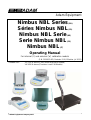
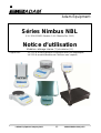
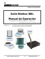
Nimbus NBL Series
(EN)
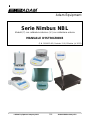
Séries Nimbus NBL
(FR)
Nimbus NBL Serie
(DE)
Serie Nimbus NBL
(ES)
Nimbus NBL
(IT)
Operating Manual
For internal (‘i’) and external (‘e’) calibration models
(P.N. 3016612481, Revision 2.00, Effective Jul 2015)
Software rev.: V3.1145 & above (Force Motor Analytical Models)
V4.1826 & above (Precision Load Cell Models)

© Adam Equipment Company 2015
ENGLISH: P 1 - 48
FRANÇAIS: P 49 - 99
DEUTSCH: P 100 - 154
ESPAÑOL: P 155 - 207
ITALIANO: P 208 - 259
EU DECLARATION: P 260

EN
© Adam Equipment Company 2015
1
3016612481Rev2.00-Jul15
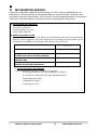
TABLE OF CONTENTS
1 KNOW YOUR BALANCE ........................................................................................................ 2
2 PRODUCT OVERVIEW .......................................................................................................... 3
3 PRODUCT SPECIFICATIONS ................................................................................................ 4
4 UNPACKING THE BALANCE ............................................................................................... 10
5 LOCATING THE BALANCE .................................................................................................. 10
6 SETTING UP THE BALANCE ............................................................................................... 11
6.1 ASSEMBLING THE BALANCE ...................................................................................... 11
6.1.1 Levelling the balance ............................................................................................... 11
6.1.2 Warm-Up Time ........................................................................................................ 11
6.1.3 Weighing.................................................................................................................. 11
6.2 CALIBRATION .............................................................................................................. 12
6.2.1 Manual Calibration ................................................................................................... 12
6.2.2 Calibration using Internal Calibration mass (if fitted) ................................................ 12
6.2.3 Calibration using External Calibration mass ............................................................. 12
6.2.4 Automatic Calibration ............................................................................................... 12
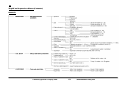
6.2.5 Calibration Errors ..................................................................................................... 13
7 DISPLAY ............................................................................................................................... 14
7.1 SYMBOLS AND TEXT................................................................................................... 14
8 KEYPAD ............................................................................................................................... 15
8.1 NUMERIC ENTRY METHOD ........................................................................................ 16
9 INPUT/OUTPUT .................................................................................................................... 17
10 OPERATIONS .................................................................................................................... 18
10.1 INITIALISATION ............................................................................................................ 18
10.2 PASSCODES ................................................................................................................ 18
10.3 WEIGHING .................................................................................................................... 19
10.4 FUNCTIONS ................................................................................................................. 20
10.4.1 Parts Counting ..................................................................................................... 21
10.4.2 Percentage Weighing ........................................................................................... 22
10.4.3 Dynamic (Animal) Weighing ................................................................................. 23
10.4.4 Density Determination .......................................................................................... 25
11 RS-232 INTERFACE .......................................................................................................... 27
11.1 HARDWARE ................................................................................................................. 27
11.2 OUTPUT FORMATS ..................................................................................................... 27
11.2.1 SINGLE-LINE OUTPUT FORMAT ....................................................................... 27
11.2.2 STANDARD OUTPUT FORMAT .......................................................................... 28
11.2.3 CUSTOM OUTPUT FORMAT .............................................................................. 28
11.3 INPUT COMMANDS USING REMOTE KEYS ............................................................... 29
11.3.1 Invalid Input Command: ....................................................................................... 29
12 ERROR CHECKING .......................................................................................................... 31
13 SUPERVISOR MENUS ...................................................................................................... 32
13.1 ENABLE WEIGHING UNITS ......................................................................................... 32
13.2 ENABLE WEIGHING MODES ....................................................................................... 32
13.3 ENABLE SERIAL INTERFACE PARAMETERS ............................................................ 32
13.4 FORMAT OF CUSTOM FORMS #1 and #2 ................................................................... 33
13.5 SETUP PARAMETERS ................................................................................................. 34
13.6 CALIBRATION SETUP .................................................................................................. 35
13.7 PASSCODES ................................................................................................................ 35
14 ACCESSORIES & SPARE PARTS .................................................................................... 37
15 SAFETY AND MAINTENANCE .......................................................................................... 39
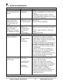
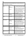
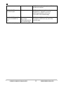
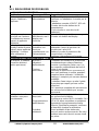
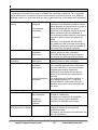
16 TROUBLE-SHOOTING ...................................................................................................... 40
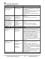
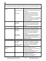
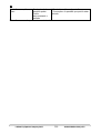
16.1 TROUBLE-SHOOTING GUIDE. .................................................................................... 41
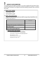
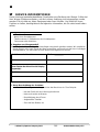
17 SERVICE INFORMATION .................................................................................................. 43
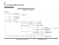
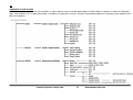
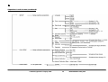
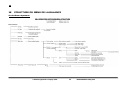
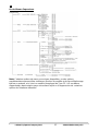
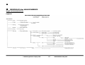
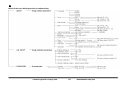
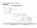
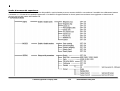
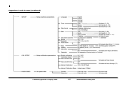
18 BALANCE MENU STRUCTURE ........................................................................................ 44
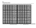
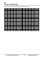
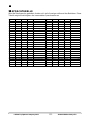
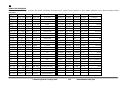
19 LANGUAGE TABLE ........................................................................................................... 47
20 WARRANTY INFORMATION ............................................................................................. 48

EN
© Adam Equipment Company 2015
2
3016612481Rev2.00-Jul15
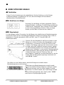
1 KNOW YOUR BALANCE
Thank you for selecting the Nimbus Balance from Adam Equipment.
This Instruction Manual will familiarise you with the installation, use, general maintenance
etc. of the balance, and will guide you through the various applications. It also covers
accessories, trouble-shooting, after sales service information, and other important
information.
These balances are highly accurate precision instruments and contain sensitive
mechanisms and components. They should be transported and handled with care. When
in operation, be careful to place loads gently on the weighing surface and do not overload
or exceed recommended maximum capacity of the instrument or damage may occur.
Please read this Manual thoroughly before starting operation. If you need any
clarifications, feel free to contact your supplier or Adam Equipment.

EN
© Adam Equipment Company 2015
3
3016612481Rev2.00-Jul15
2 PRODUCT OVERVIEW
The Nimbus balances are ideal for laboratory and general purpose weighing. They can
also be used for some advanced weighing functions.
FEATURES:
• External menu-driven calibration allowing user-selectable range of calibration weights.
• Internal calibration (option) for outstanding accuracy without the need for manual calibration.
• Mains powered, with some models offering rechargeable battery pack option for cordless use.
• Solid die-cast aluminium alloy construction with 304 grade stainless steel pan for durability and
easy cleaning.
• Large easy to read LCD display with backlight.
• Standard applications include weighing, percentage weighing, parts counting, dynamic (animal)
weighing (not ‘j’ models), and solid and liquid density determination.
• Bi-directional RS-232 interface and USB interface as standard.
• External display option
• Can be configured to print a GLP Compliant report after each calibration to include the time, date,
balance number and a verification of the calibration.
• Force-restoration mechanism for supreme accuracy, or alloy load cell technology for stable yet
accurate weighing.
• Automatic temperature compensation.
• Multiple weighing units.
• Easy to use, wipe-clean sealed membrane keypad.
• Below balance weighing facility (accessory hook required).
• Display in a choice of 4 languages – English, German, French & Spanish.
• Password protection.
• Security locking point.

EN
© Adam Equipment Company 2015
4
3016612481Rev2.00-Jul15
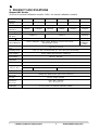
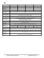
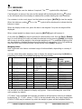
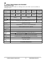
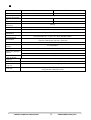
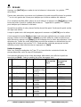
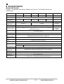
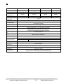
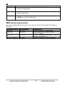
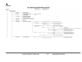
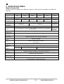
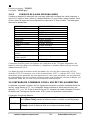
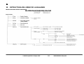
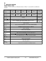
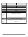
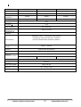
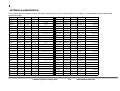
3 PRODUCT SPECIFICATIONS
Nimbus NBL Models
(Suffix e for external calibration models, Suffix i for internal calibration models)
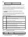
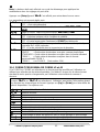
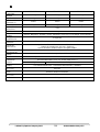
Model # NBL 84 e/i NBL 124 e/i NBL 164 e/i NBL 214 e/i NBL 254 e/i NBL 214j e/i
Maximum
Capacity
80 g 120 g 160 g 210 g 250 g 210 g
Readability (d) 0.0001 g 0.0002 g
Number of
intervals n=
800000 1200000 1600000 2100000 2500000 2100000
Min. weight 0.01 g 0.02 g
Repeatability
(Std. Dev)
0.00015 g 0.0002 g 0.0004 g
Linearity + 0.0002 g 0.0004 g
Units of Measure
grams, milligrams, carats, grains, Newtons, ounces, troy ounces,
pennyweight, custom
grams,
milligrams,
carats,
Stabilization
Time
Typically 3 seconds
Operating Temp 15ºC to 35ºC recommended, 40 – 60 % RH (non-condensing)
Power Supply
External mains power adapter - supplied as standard
(Input Voltage 100–240 VAC, 50/60 Hz)
Input Voltage 18 VDC - 830 mA
Weighing
mechanism
Force Restoration Balance Motor
Calibration Suffix i = internal calibration mechanism, e = external calibration only
External
Calibration Mass
Recommended OIML class: E2, ASTM / ANSI class: 1
50 g 100 g 100 g
Display LCD with blue backlight, 7 characters, 20 mm high, and symbols
Draft Shield
(w x d x h)
Sliding door Draft Shield (165 x 145 x 240 mm)
Pan Size Round, 90mm diameter
Overall
Dimensions
(w x d x h)
220 x 310 x 323 mm
8.7 x 12.2 x 12.7 in
Net Weight
5.2 kg / 11 lb 9 oz (external calibration model)
5.9 kg / 13 lb 0 oz (internal calibration model)

EN
© Adam Equipment Company 2015
5
3016612481Rev2.00-Jul15
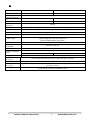
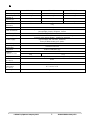
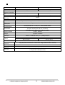
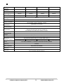
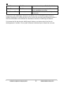
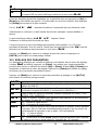
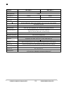
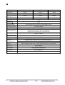
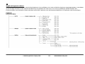
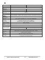
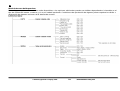
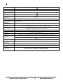
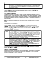
Model # NBL 223 e / i NBL 423 e / i
Maximum Capacity 220 g 420 g
Readability (d) 0.001 g
Number of intervals
n=
220000 420000
Min. 0.02 g 0.02 g
Repeatability
(Std. Dev)
0.002 g
Linearity + 0.002 g
Units of Measure
grams, milligrams, carats, grains, Newtons, ounces, troy ounces, pennyweight, custom
Stabilization Time Typically 3 seconds
Operating Temp 15ºC to 35ºC recommended, 40 – 60 % RH (non-condensing)
Power Supply
External mains power adapter - supplied as standard
(Input Voltage 100–240 VAC, 50/60 Hz)
Factory-fit NiMH battery pack option.
Input Voltage 18 VDC - 830 mA
Weighing
mechanism
Precision Load Cell
Calibration Suffix i = internal calibration mechanism, e = external calibration only,
External Calibration
Mass
Recommended OIML class: E2, ASTM / ANSI class: 2
100 g 200 g
Display LCD with blue backlight, 7 characters, 20 mm high, and symbols
Draft Shield
(w x d x h)
Glass Ring Draft Shield With Alloy Lid (180 mm diam. x 90 mm)
Pan Size Round, 120 mm diameter
Overall Dimensions
(w x d x h)
220 x 310 x 90 mm without breeze ring
8.7 x 12.2 x 3.5 in
Net Weight
3.1 kg / 6 lb 12 oz (external calibration model)
3.7 kg / 8 lb 8 oz (internal calibration model)

EN
© Adam Equipment Company 2015
6
3016612481Rev2.00-Jul15
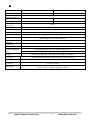
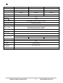
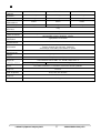
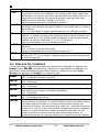
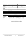
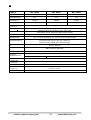
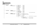
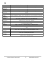
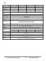
Model # NBL 623 e / i NBL 823 e / i
Maximum Capacity 620 g 820 g
Readability (d) 0.001 g
Number of intervals
n=
620000 820000
Min. weight 0.02 g 0.02 g
Repeatability
(Std. Dev)
0.002 g
Linearity + 0.002 g
Units of Measure
grams, milligrams, carats, grains, Newtons, ounces, troy ounces, pennyweight, custom
Stabilization Time Typically 3 seconds
Operating Temp 15ºC to 35ºC recommended, 40 – 60 % RH (non-condensing)
Power Supply
External mains power adapter - supplied as standard
(Input Voltage 100–240 VAC, 50/60 Hz)
Input Voltage 18 VDC - 830 mA
Weighing
mechanism
Force Restoration Balance Motor
Calibration Suffix i = internal calibration mechanism, e = external calibration only
External Calibration
Mass
Recommended OIML class: E2, ASTM / ANSI class: 2
500 g
Display LCD with blue backlight, 7 characters, 20 mm high, and symbols
Draft Shield
(w x d x h)
Glass Ring Draft Shield With Alloy Lid (180 mm diam. x 90 mm)
Pan Size Round, 160 mm diameter
Overall Dimensions
(w x d x h)
220 x 310 x 90 mm without breeze ring
8.7 x 12.2 x 3.5 in
Net Weight
4.0 kg / 8 lb 13 oz (external calibration model)
4.8 kg / 10 lb 9 oz (internal calibration model)

EN
© Adam Equipment Company 2015
7
3016612481Rev2.00-Jul15
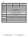
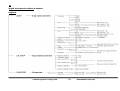
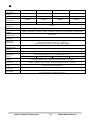
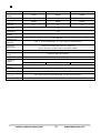
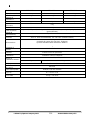
Model # NBL 1602 e / i NBL 2602 e / i NBL 3602 e / i NBL 4602 e / i
Maximum Capacity
1600 g 2600 g 3600 g 4600 g
Readability (d) 0.01 g 0.01 g 0.01 g 0.01 g
Number of
intervals n=
160000 260000 360000 460000
Min. weight 0.2 g 0.2 g 0.2 g 0.2 g
Repeatability
(Std. Dev)
0.02 g
Linearity + 0.02 g
Units of Measure
grams, carats, grains, Newtons, ounces, troy ounces,
pennyweight, pounds, kilograms, custom
Stabilization Time Typically 3 seconds
Operating Temp 15ºC to 35ºC recommended, 40 – 60 % RH (non-condensing)
Power Supply
External mains power adapter - supplied as standard
(Input Voltage 100–240 VAC, 50/60 Hz)
Factory-fit NiMH battery pack option.
Input Voltage 18 VDC - 830 mA
Weighing
mechanism
Precision Load Cell
Calibration Suffix i = internal calibration mechanism, e = external calibration only
External
Calibration Mass
Recommended OIML class: F1, ASTM / ANSI class: 3
1 kg 2 kg 2 kg 2 kg
Display LCD with blue backlight, 7 characters, 20 mm high, and symbols
Draft Shield
(w x d x h)
None
Pan Size Round, 160 mm diameter
Overall
Dimensions
(w x d x h)
220 x 310 x 90 mm
8.7 x 12.2 x 3.5 in
Net Weight
3.1 kg / 6 lb 14 oz (external calibration model)
3.9 kg / 8 lb 10 oz (internal calibration model)

EN
© Adam Equipment Company 2015
8
3016612481Rev2.00-Jul15
Model # NBL 4201e NBL 6201e NBL 8201e
Maximum Capacity
4200g 6200g 8200g
Readability (d) 0.1g 0.1g 0.1g
Number of
intervals n=
42000 62000 82000
Min. weight 2 g 2 g 2 g
Repeatability
(Std. Dev)
0.1g
Linearity + 0.1g
Units of Measure
grams, carats, grains, Newtons, ounces, troy ounces,
pennyweight, pounds, kilograms, custom
Stabilization Time Typically 3 seconds
Operating Temp 15ºC to 35ºC recommended, 40 – 60 % RH (non-condensing)
Power Supply
External mains power adapter - supplied as standard
(Input Voltage 100–240 VAC, 50/60 Hz)
Factory-fit NiMH battery pack option.
Input Voltage 18 VDC - 830 mA
Weighing
mechanism
Precision Load Cell
Calibration External calibration only
External
Calibration Mass
Recommended OIML class: F2, ASTM / ANSI class: 4
2 kg 2 kg
Display LCD with blue backlight, 7 characters, 20 mm high, and symbols
Draft Shield
(w x d x h)
None
Pan Size Round, 160 mm diameter
Overall
Dimensions
(w x d x h)
220 x 310 x 90 mm
8.7 x 12.2 x 3.5 in
Net Weight 3.1 kg / 6 lb 14 oz

EN
© Adam Equipment Company 2015
9
3016612481Rev2.00-Jul15
Model # NBL 12001e NBL 16001e NBL 22001e
Maximum Capacity
12000g 16000g 22000g
Readability (d) 0.1g 0.1g 0.1g
Number of
intervals n=
120000 160000 220000
Min. weight 2 g 2 g 2 g
Repeatability
(Std. Dev)
0.1g
Linearity + 0.1g
Units of Measure
grams, carats, grains, Newtons, ounces, troy ounces,
pennyweight, pounds, kilograms, custom
Stabilization Time Typically 3 seconds
Operating Temp 15ºC to 35ºC recommended, 40 – 60 % RH (non-condensing)
Power Supply
External mains power adapter - supplied as standard
(Input Voltage 100–240 VAC, 50/60 Hz)
Factory-fit NiMH battery pack option.
Input Voltage 18 VDC - 830 mA
Weighing
mechanism
Precision Load Cell
Calibration External calibration only
External
Calibration Mass
Recommended OIML class: F2, ASTM / ANSI class: 4
5 kg 10 kg 10 kg
Display LCD with blue backlight, 7 characters, 20 mm high, and symbols
Draft Shield
(w x d x h)
None
Pan Size 390 X 290 mm
Overall
Dimensions
(w x d x h)
390 x 480 x 100 mm (590 mm tall with pole accessory)
8.7 x 12.2 x 3.5 in
Net Weight 7.6 kg / 16 lb 12 oz

EN
© Adam Equipment Company 2015
10
3016612481Rev2.00-Jul15
4 UNPACKING THE BALANCE
Remove the balance from the packing by carefully lifting it out of the box. Inside the box
you will find everything needed to start using the balance-
• AC mains power adapter & cord
• Stainless Steel Top Pan
• Alloy sub-pan
• Draught shield (for mg models only)
• User documentation
Carefully follow the quick setup guide included to assemble the balance.
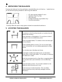
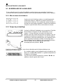
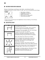
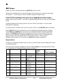
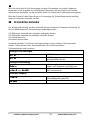
5 LOCATING THE BALANCE
The balance should not be placed in a location that will
reduce the accuracy.
Avoid extremes of temperature. Do not place in direct
sunlight or near air conditioning vents.
Avoid unsuitable tables. The table or floor must be rigid
and not vibrate.
Avoid unstable power sources. Do not use near large
users of electricity such as welding equipment or large
motors.
Do not place near vibrating machinery.
Avoid high humidity that might cause condensation.
Avoid direct contact with water. Do not spray or immerse
the balances in water.
Avoid air movement such as from fans or opening doors.
Do not place near open windows or air-conditioning
vents.
Keep the balance clean. Do not stack material on the
balances when they are not in use.
Avoid sources of static electricity. This can affect
measurement accuracy and may damage sensitive
electronics.

EN
© Adam Equipment Company 2015
11
3016612481Rev2.00-Jul15
6 SETTING UP THE BALANCE
6.1 ASSEMBLING THE BALANCE
Carefully follow the included quick setup guide to assemble the balance. Ensure that you
locate the balance on a solid level surface, free from vibration.
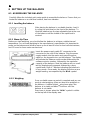
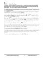
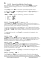
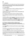
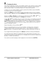
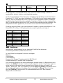
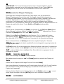
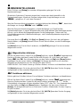
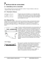
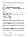
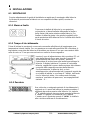
6.1.1 Levelling the balance
After placing the balance in a suitable location, level it
by using the spirit level on the front of the balance. To
level the balance turn the two adjustable feet at the rear
of the balance until the bubble in the spirit level is
centred.
6.1.2 Warm-Up Time
Before you start weighing, you should allow the balance to achieve a stable internal
temperature. For accurate weighing to the manufacturer’s specification it is important to
power on the balance and allow to warm up for at least 6 hours for load cell mechanisms,
and 12 hours for force motor mechanisms.
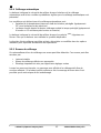
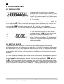
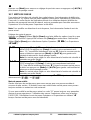
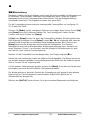
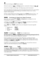
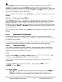
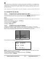
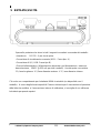
6.1.3 Weighing
Insert the power supply cable DC connector to the
connector on the rear of the balance. Plug the power
supply module into the mains and press the power
switch on the keypad to turn on the balance. The display
will indicate the balance serial number followed by the
software revision number, followed by the maximum
capacity of the balance. Next the balance will run a self-
test by displaying all segments followed by a busy
symbol and a line of 7 dashes indicating the balance is
in busy mode. Once ready, the display will show a zero
weight reading, accompanied by the 0 symbol.
Once a suitable warm-up period is complete and you are
ready to start weighing, place an item to be weighed on
the balance. A stable symbol is shown when the
balance is in stable condition. It will turn off if the
balance is not stable.
Exact zero is shown when the “0“ symbol is visible
on the top left of the display area.

EN
© Adam Equipment Company 2015
12
3016612481Rev2.00-Jul15
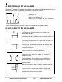
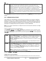
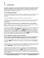
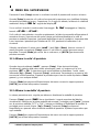
6.2 CALIBRATION
Units with an ‘i’ suffix can be calibrated using either internal calibration mechanism or by
using an external mass. Units with an ‘e’ suffix can only be calibrated with an external
mass. Internal calibration option must be enabled in the setup menu options or else
external calibration mode will be used when the [Cal] key is pressed.
6.2.1 Manual Calibration
Pressing the [Cal] key will start calibration. Calibration can also be initiated by a change
in internal temperature or a set time period as determined by the user.
Pressing [
0/T
] will abort the calibration at any time.
Calibration should be performed carefully and in conditions of no vibration, air movement
or other disturbance. Make sure the pan is empty, clean, and correctly fitted.
6.2.2 Calibration using Internal Calibration mass (if fitted)
Note: Internal calibration (if fitted) will only initiate if it is enabled as the default calibration
method in the Supervisor level calibration setup menu.
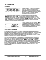
On pressing the [Cal] key the display will show the busy symbol and a line of 7 dashes
and then after a few seconds will display ‘CALIBRA
CALIBRACALIBRA
CALIBRA’. Then the busy symbol and a line of 7
dashes will reappear, followed by ‘CAL On
CAL OnCAL On
CAL On’. Then ‘CALIbrA
CALIbrACALIbrA
CALIbrA’ will appear again, followed by
the busy symbol and a line of dashes. Finally ‘CAL OFF
CAL OFFCAL OFF
CAL OFF’ will be displayed, followed by a
beep and the busy symbol and a line of dashes. A final beep will sound the end of
calibration and the display should return to ‘0
00
0.000
000000
000 g’ or similar. Internal calibration is now
complete and normal operations may proceed.
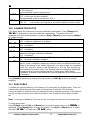
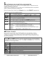
6.2.3 Calibration using External Calibration mass
Note: Calibration mass used should be a known accurate item, ideally with an OIML
or ASTM/ANSI classification appropriate to the accuracy of the balance.
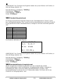
On pressing the [Cal] key the display will show the balance setting a new Zero condition
by showing “LOAD 0
LOAD 0LOAD 0
LOAD 0”. Make sure the pan is empty then press the [Setup] key to continue
The display will show the busy symbol and a line of dashes and then after a few seconds
will display the required calibration mass. For example, for a 213e model the display will
be “LOAd 100
LOAd 100LOAd 100
LOAd 100 g” where 100 g is the required calibration mass.
Place the selected mass on the balance. The balance will automatically continue. The
display will show the busy symbol and a line of dashes and after calibration is complete it
will sound a beep and display “vNLOAD
vNLOADvNLOAD
vNLOAD”. Remove the weight. Another beep will be heard
confirming the unloading action. The balance will display the busy symbol and a line of
dashes for a few seconds and then sound a beep and return to normal weighing.
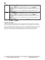
6.2.4 Automatic Calibration
The balance will indicate the need for calibration when the balance has automatic
calibration enabled and the set pre-conditions for automatic calibration have been met.
Conditions that will trigger an automatic calibration are:

EN
© Adam Equipment Company 2015
13
3016612481Rev2.00-Jul15
• Internal temperature change greater than a pre-set amount (typically 2ºC for
Precision balances).
• Time since last calibration exceeds a pre-set time (typically 4 hours, or 15 minutes
after power is applied).
The balance will indicate the need for calibration to be carried out by flashing the “
CAL
”
symbol on the display. As soon as the balance is calibrated the symbol will be turned off.
The Auto calibration feature can be enabled, disabled or changed within the user options
to meet the requirements of the users.
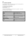
6.2.5 Calibration Errors
Occasionally during calibration an error will be detected. These errors can be caused by:
• Unstable readings
• Improper calibration weights being used
• Large shifts of zero from the factory settings
When an error is found a displayed message will be shown and the calibration must be
done again. If the balance has error messages more than once it is possible the
mechanics have been damaged.

EN
© Adam Equipment Company 2015
14
3016612481Rev2.00-Jul15
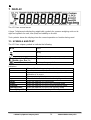
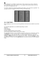
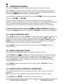
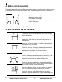
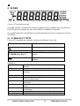
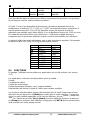
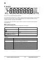
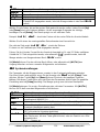
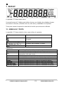
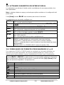
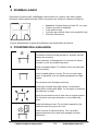
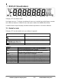
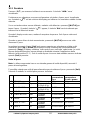
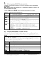
7 DISPLAY
The LCD has several areas-
A large 7 digit area to display the weight with symbols for common weighing units on its
right and symbols for zero, tare (Net) and stability on the left.
Text symbols above the display show the current operation or function being used.
7.1 SYMBOLS AND TEXT
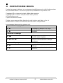
The LCD has unique symbols to indicate the following:
0
Zero
Busy
Stable
g,
mg, kg,
ct,
dwt, GN, ozt,
oz,
N, Custom, g/cc, Pcs, %,
Symbols shown for units and modes
Battery charge symbol
Indicators:
“CAL”
When calibration is occurring or about to occur
“
T
”
For a time driven calibration
“ºC”
When a temperature is shown or a temperature driven
calibration is to occur
“Net”
When a net weight is shown
“
Dynamic
”
When the balance is in the animal weighing mode
“
Hold
”
When the balance is in hold mode
“
P
arts
”
When the balance is in the Parts counting mode
“
P
ercent
”
When the balance is in the Percent weighing mode
“Density S
olid
”
When the balance is in the Solid Density mode
“Density L
iquid
”
When the balance is in the Liquid Density mode

EN
© Adam Equipment Company 2015
15
3016612481Rev2.00-Jul15
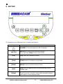
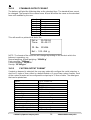
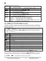
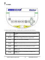
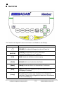
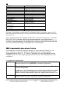
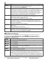
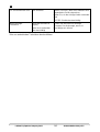
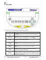
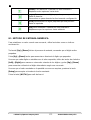
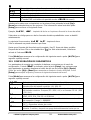
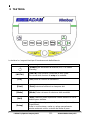
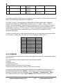
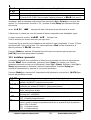
8 KEYPAD
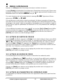
The keypad has the following keys to operate the balance.
Keys
Primary function
[POWER] To turn the balance to ON or Standby
[0/T]
[0/T] A combined zero and tare function.
To escape from setup functions and modes.
[Cal]
[Cal] Starts the calibration function
[Print] [Print] Instructs the balance to print data
[Mode] [Mode] Enters the Mode Selection Menu
[Unit]
[Unit] Selects weighing units by cycling through a set of
enabled units.
[Setup]
[
S
etup
]
Enters the setup parameters (Supervisor Menus).
Enters a function or saves a value while manually entering
unit weight or check weighing limits.

EN
© Adam Equipment Company 2015
16
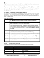
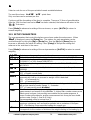
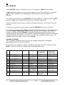
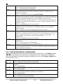
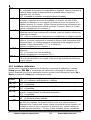
3016612481Rev2.00-Jul15
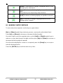
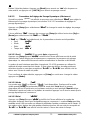
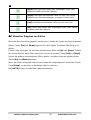
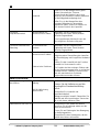
[Down] To decrement or change a displayed value or scroll
through options backwards
[Right]
To advance a flashing digit by one position to the
right.
To go back by one step during setup functions
[Left] To advance a flashing digit by one position to the left
[Up] To increase or change a displayed value or scroll
through options forward
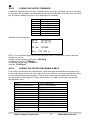
8.1 NUMERIC ENTRY METHOD
To set a value when required, use the keys as given below:-
[Up] and [Down] symbol keys start entry process, causing the active digit to flash.
Press [Up] and [Down] to increase or decrease the flashing digit.
Once each digit is set to the required value, use the [Left] and [Right] symbol keys to
advance or move back through the digits and then press [Up] and [Down] to increase or
decrease the flashing digit as required.
Once the value displayed on screen is as required, press the [Setup] key to accept or
enter the displayed value.
Press the [0/T] key to exit the menu at any time.

EN
© Adam Equipment Company 2015
17
3016612481Rev2.00-Jul15
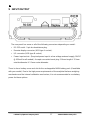
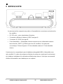
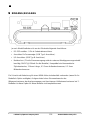
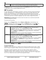
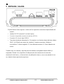
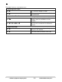
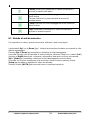
9 INPUT/OUTPUT
The rear panel has some or all of the following connectors depending on model:
• RS-232 serial - 9 pin d-subminiature plug.
• Remote display connector (USB type A socket).
• I/O connector (USB type B socket).
• Power input socket. (Required power input is a low-voltage external supply, 18VDC
@ 830mA for all models). Accepts concentric barrel plug 11.4mm length X 5.5mm
outside diameter X 2.1mm centre diameter.
There is also a battery cover and slot for the rechargeable NiMH battery pack (if available
with your model). Due to the high power requirements of the analytical balance weighing
mechanism and the internal calibration mechanism, it is not recommended to use battery
power for these options.

EN
© Adam Equipment Company 2015
18
3016612481Rev2.00-Jul15
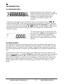
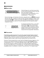
10 OPERATIONS
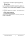
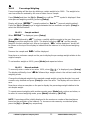
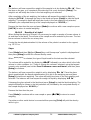
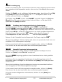
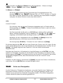
10.1 INITIALISATION
When the balance is first switched on, it will
display the balance serial number, the software
revision, the model capacity and then all
segments on the display will be shown.
Overall the time taken is usually 5 -10
seconds.
If Operator and Supervisor passcodes have been set, the display will show “PASS CD
PASS CDPASS CD
PASS CD”,
shortly followed by “0
00
0”. In this case you must enter the passcode to continue, using the
numeric entry method (see section Error! Reference source not found.). If passcode is
incorrectly entered then the message “ER CODE
ER CODEER CODE
ER CODE” will flash, shortly followed by “0
00
0”. Once a
passcode is correctly entered, or if passcodes have not been set, the balance will
continue as below.
The display will show zero reading along with
the zero symbol “0” and the weighing unit
last used. If automatic time calibration is
enabled the balance will calibrate 15 minutes
after power up, or again after the pre-set time
interval.
10.2 PASSCODES
This equipment has passcode security functions which can restrict certain operations to
particular users. Supervisor and Operator modes are available. If no passcode is set then
the default access is Supervisor level. Setting a Supervisor passcode gives the option to
lock down key parameters so that they are not available to be changed by operator-level
staff.
If a passcode has been set to limit access to the weighing functions of the balance then
when reset or turned on, or when the [Setup] key is pressed in Operator mode, the display
will show “PASS CD
PASS CDPASS CD
PASS CD” followed by “0
00
0”. Use the numeric entry method (see section 8.1) to
enter either the operator or supervisor code depending on the access level required. The
display show the digits entered as they are set. The active digit will have the “-“ symbol
flashing. Make sure to enter the correct passcode to continue. See Section 13.7 for
details.
La page est en cours de chargement...
La page est en cours de chargement...
La page est en cours de chargement...
La page est en cours de chargement...
La page est en cours de chargement...
La page est en cours de chargement...
La page est en cours de chargement...
La page est en cours de chargement...
La page est en cours de chargement...
La page est en cours de chargement...
La page est en cours de chargement...
La page est en cours de chargement...
La page est en cours de chargement...
La page est en cours de chargement...
La page est en cours de chargement...
La page est en cours de chargement...
La page est en cours de chargement...
La page est en cours de chargement...
La page est en cours de chargement...
La page est en cours de chargement...
La page est en cours de chargement...
La page est en cours de chargement...
La page est en cours de chargement...
La page est en cours de chargement...
La page est en cours de chargement...
La page est en cours de chargement...
La page est en cours de chargement...
La page est en cours de chargement...
La page est en cours de chargement...
La page est en cours de chargement...
La page est en cours de chargement...
La page est en cours de chargement...
La page est en cours de chargement...
La page est en cours de chargement...
La page est en cours de chargement...
La page est en cours de chargement...
La page est en cours de chargement...
La page est en cours de chargement...
La page est en cours de chargement...
La page est en cours de chargement...
La page est en cours de chargement...
La page est en cours de chargement...
La page est en cours de chargement...
La page est en cours de chargement...
La page est en cours de chargement...
La page est en cours de chargement...
La page est en cours de chargement...
La page est en cours de chargement...
La page est en cours de chargement...
La page est en cours de chargement...
La page est en cours de chargement...
La page est en cours de chargement...
La page est en cours de chargement...
La page est en cours de chargement...
La page est en cours de chargement...
La page est en cours de chargement...
La page est en cours de chargement...
La page est en cours de chargement...
La page est en cours de chargement...
La page est en cours de chargement...
La page est en cours de chargement...
La page est en cours de chargement...
La page est en cours de chargement...
La page est en cours de chargement...
La page est en cours de chargement...
La page est en cours de chargement...
La page est en cours de chargement...
La page est en cours de chargement...
La page est en cours de chargement...
La page est en cours de chargement...
La page est en cours de chargement...
La page est en cours de chargement...
La page est en cours de chargement...
La page est en cours de chargement...
La page est en cours de chargement...
La page est en cours de chargement...
La page est en cours de chargement...
La page est en cours de chargement...
La page est en cours de chargement...
La page est en cours de chargement...
La page est en cours de chargement...
La page est en cours de chargement...
La page est en cours de chargement...
La page est en cours de chargement...
La page est en cours de chargement...
La page est en cours de chargement...
La page est en cours de chargement...
La page est en cours de chargement...
La page est en cours de chargement...
La page est en cours de chargement...
La page est en cours de chargement...
La page est en cours de chargement...
La page est en cours de chargement...
La page est en cours de chargement...
La page est en cours de chargement...
La page est en cours de chargement...
La page est en cours de chargement...
La page est en cours de chargement...
La page est en cours de chargement...
La page est en cours de chargement...
La page est en cours de chargement...
La page est en cours de chargement...
La page est en cours de chargement...
La page est en cours de chargement...
La page est en cours de chargement...
La page est en cours de chargement...
La page est en cours de chargement...
La page est en cours de chargement...
La page est en cours de chargement...
La page est en cours de chargement...
La page est en cours de chargement...
La page est en cours de chargement...
La page est en cours de chargement...
La page est en cours de chargement...
La page est en cours de chargement...
La page est en cours de chargement...
La page est en cours de chargement...
La page est en cours de chargement...
La page est en cours de chargement...
La page est en cours de chargement...
La page est en cours de chargement...
La page est en cours de chargement...
La page est en cours de chargement...
La page est en cours de chargement...
La page est en cours de chargement...
La page est en cours de chargement...
La page est en cours de chargement...
La page est en cours de chargement...
La page est en cours de chargement...
La page est en cours de chargement...
La page est en cours de chargement...
La page est en cours de chargement...
La page est en cours de chargement...
La page est en cours de chargement...
La page est en cours de chargement...
La page est en cours de chargement...
La page est en cours de chargement...
La page est en cours de chargement...
La page est en cours de chargement...
La page est en cours de chargement...
La page est en cours de chargement...
La page est en cours de chargement...
La page est en cours de chargement...
La page est en cours de chargement...
La page est en cours de chargement...
La page est en cours de chargement...
La page est en cours de chargement...
La page est en cours de chargement...
La page est en cours de chargement...
La page est en cours de chargement...
La page est en cours de chargement...
La page est en cours de chargement...
La page est en cours de chargement...
La page est en cours de chargement...
La page est en cours de chargement...
La page est en cours de chargement...
La page est en cours de chargement...
La page est en cours de chargement...
La page est en cours de chargement...
La page est en cours de chargement...
La page est en cours de chargement...
La page est en cours de chargement...
La page est en cours de chargement...
La page est en cours de chargement...
La page est en cours de chargement...
La page est en cours de chargement...
La page est en cours de chargement...
La page est en cours de chargement...
La page est en cours de chargement...
La page est en cours de chargement...
La page est en cours de chargement...
La page est en cours de chargement...
La page est en cours de chargement...
La page est en cours de chargement...
La page est en cours de chargement...
La page est en cours de chargement...
La page est en cours de chargement...
La page est en cours de chargement...
La page est en cours de chargement...
La page est en cours de chargement...
La page est en cours de chargement...
La page est en cours de chargement...
La page est en cours de chargement...
La page est en cours de chargement...
La page est en cours de chargement...
La page est en cours de chargement...
La page est en cours de chargement...
La page est en cours de chargement...
La page est en cours de chargement...
La page est en cours de chargement...
La page est en cours de chargement...
La page est en cours de chargement...
La page est en cours de chargement...
La page est en cours de chargement...
La page est en cours de chargement...
La page est en cours de chargement...
La page est en cours de chargement...
La page est en cours de chargement...
La page est en cours de chargement...
La page est en cours de chargement...
La page est en cours de chargement...
La page est en cours de chargement...
La page est en cours de chargement...
La page est en cours de chargement...
La page est en cours de chargement...
La page est en cours de chargement...
La page est en cours de chargement...
La page est en cours de chargement...
La page est en cours de chargement...
La page est en cours de chargement...
La page est en cours de chargement...
La page est en cours de chargement...
La page est en cours de chargement...
La page est en cours de chargement...
La page est en cours de chargement...
La page est en cours de chargement...
La page est en cours de chargement...
La page est en cours de chargement...
La page est en cours de chargement...
La page est en cours de chargement...
La page est en cours de chargement...
La page est en cours de chargement...
La page est en cours de chargement...
La page est en cours de chargement...
La page est en cours de chargement...
La page est en cours de chargement...
La page est en cours de chargement...
La page est en cours de chargement...
La page est en cours de chargement...
La page est en cours de chargement...
La page est en cours de chargement...
La page est en cours de chargement...
La page est en cours de chargement...
La page est en cours de chargement...
La page est en cours de chargement...
La page est en cours de chargement...
La page est en cours de chargement...
La page est en cours de chargement...
La page est en cours de chargement...
La page est en cours de chargement...
La page est en cours de chargement...
La page est en cours de chargement...
La page est en cours de chargement...
La page est en cours de chargement...
-
 1
1
-
 2
2
-
 3
3
-
 4
4
-
 5
5
-
 6
6
-
 7
7
-
 8
8
-
 9
9
-
 10
10
-
 11
11
-
 12
12
-
 13
13
-
 14
14
-
 15
15
-
 16
16
-
 17
17
-
 18
18
-
 19
19
-
 20
20
-
 21
21
-
 22
22
-
 23
23
-
 24
24
-
 25
25
-
 26
26
-
 27
27
-
 28
28
-
 29
29
-
 30
30
-
 31
31
-
 32
32
-
 33
33
-
 34
34
-
 35
35
-
 36
36
-
 37
37
-
 38
38
-
 39
39
-
 40
40
-
 41
41
-
 42
42
-
 43
43
-
 44
44
-
 45
45
-
 46
46
-
 47
47
-
 48
48
-
 49
49
-
 50
50
-
 51
51
-
 52
52
-
 53
53
-
 54
54
-
 55
55
-
 56
56
-
 57
57
-
 58
58
-
 59
59
-
 60
60
-
 61
61
-
 62
62
-
 63
63
-
 64
64
-
 65
65
-
 66
66
-
 67
67
-
 68
68
-
 69
69
-
 70
70
-
 71
71
-
 72
72
-
 73
73
-
 74
74
-
 75
75
-
 76
76
-
 77
77
-
 78
78
-
 79
79
-
 80
80
-
 81
81
-
 82
82
-
 83
83
-
 84
84
-
 85
85
-
 86
86
-
 87
87
-
 88
88
-
 89
89
-
 90
90
-
 91
91
-
 92
92
-
 93
93
-
 94
94
-
 95
95
-
 96
96
-
 97
97
-
 98
98
-
 99
99
-
 100
100
-
 101
101
-
 102
102
-
 103
103
-
 104
104
-
 105
105
-
 106
106
-
 107
107
-
 108
108
-
 109
109
-
 110
110
-
 111
111
-
 112
112
-
 113
113
-
 114
114
-
 115
115
-
 116
116
-
 117
117
-
 118
118
-
 119
119
-
 120
120
-
 121
121
-
 122
122
-
 123
123
-
 124
124
-
 125
125
-
 126
126
-
 127
127
-
 128
128
-
 129
129
-
 130
130
-
 131
131
-
 132
132
-
 133
133
-
 134
134
-
 135
135
-
 136
136
-
 137
137
-
 138
138
-
 139
139
-
 140
140
-
 141
141
-
 142
142
-
 143
143
-
 144
144
-
 145
145
-
 146
146
-
 147
147
-
 148
148
-
 149
149
-
 150
150
-
 151
151
-
 152
152
-
 153
153
-
 154
154
-
 155
155
-
 156
156
-
 157
157
-
 158
158
-
 159
159
-
 160
160
-
 161
161
-
 162
162
-
 163
163
-
 164
164
-
 165
165
-
 166
166
-
 167
167
-
 168
168
-
 169
169
-
 170
170
-
 171
171
-
 172
172
-
 173
173
-
 174
174
-
 175
175
-
 176
176
-
 177
177
-
 178
178
-
 179
179
-
 180
180
-
 181
181
-
 182
182
-
 183
183
-
 184
184
-
 185
185
-
 186
186
-
 187
187
-
 188
188
-
 189
189
-
 190
190
-
 191
191
-
 192
192
-
 193
193
-
 194
194
-
 195
195
-
 196
196
-
 197
197
-
 198
198
-
 199
199
-
 200
200
-
 201
201
-
 202
202
-
 203
203
-
 204
204
-
 205
205
-
 206
206
-
 207
207
-
 208
208
-
 209
209
-
 210
210
-
 211
211
-
 212
212
-
 213
213
-
 214
214
-
 215
215
-
 216
216
-
 217
217
-
 218
218
-
 219
219
-
 220
220
-
 221
221
-
 222
222
-
 223
223
-
 224
224
-
 225
225
-
 226
226
-
 227
227
-
 228
228
-
 229
229
-
 230
230
-
 231
231
-
 232
232
-
 233
233
-
 234
234
-
 235
235
-
 236
236
-
 237
237
-
 238
238
-
 239
239
-
 240
240
-
 241
241
-
 242
242
-
 243
243
-
 244
244
-
 245
245
-
 246
246
-
 247
247
-
 248
248
-
 249
249
-
 250
250
-
 251
251
-
 252
252
-
 253
253
-
 254
254
-
 255
255
-
 256
256
-
 257
257
-
 258
258
-
 259
259
-
 260
260
-
 261
261
-
 262
262
-
 263
263
-
 264
264


Adam Nimbus NBL Serie Manuel utilisateur
- Taper
- Manuel utilisateur
- Ce manuel convient également à
dans d''autres langues
- italiano: Adam Nimbus NBL Serie Manuale utente
- English: Adam Nimbus NBL Serie User manual
- español: Adam Nimbus NBL Serie Manual de usuario
- Deutsch: Adam Nimbus NBL Serie Benutzerhandbuch
Autres documents
-
Comelit AD9191 Manuel utilisateur
-
-
Adam Equipment Table Top Game PW Manuel utilisateur
-
 Giropes Baxtran BAR Manuel utilisateur
-
Adam Equipment ASC Serie Manuel utilisateur
-
-
Baxtran ADA Manuel utilisateur
-
-
-
