United States Stove VG180L Le manuel du propriétaire
- Catégorie
- Poêle à bois
- Taper
- Le manuel du propriétaire

SAFETY NOTICE:
If this heater is not properly installed, a house re
may result. For your safety, follow the installation
instructions. Never use make-shift compromises
during the installation of this heater. Contact local
building or re ofcials about permits, restrictions
and installation requirements in your area.
CAUTION!
Please read this entire manual before you
install or use your new room heater. Failure
to follow instructions may result in property
damage, bodily injury, or even death.
Improper Installation Could Void Your Warranty!
SAVE THESE INSTRUCTIONS
THIS MANUAL WILL HELP YOU TO OBTAIN EFFICIENT, DEPENDABLE SERVICE FROM THE HEATER, AND ENABLE YOU
TO ORDER REPAIR PARTS CORRECTLY. KEEP IN A SAFE PLACE FOR FUTURE REFERENCE.
French version is available for download from the U. S. Stove website: http://www.usstove.com/
La version française est disponible pour téléchargement à partir du site U. S. Stove: http://www.usstove.com/
Approved for installation in the USA and Canada
CONFORMS TO UL 1482, AND CERTIFIED TO ULC-S627 AND ULC-S628
Also suitable for use in a Mobile or Manufactured home. (USA Only)
852909-3905G
MODEL: VG180L
U. S. Stove
227 Industrial Park Road P.O. Box 151
South Pittsburg, TN 37380
(800) 750-2723 • www.usstove.com
U.S. Environmental Protection Agency
Certied to comply with 2015 particulate emissions standards.

2
CAUTIONS:
• Hot while in operation. Keep children, clothing and furniture away. Contact may cause skin burns.
• Do not use chemicals or uids to ignite the re.
• Do not leave the stove unattended when the door is slightly opened.
• Do not burn garbage, ammable uid such as gasoline, naphtha or motor oil.
• Do not connect to or use in conjunction with any air distribution ductwork unless specically approved
for such installations.
• Always close the door after the ignition.
• Consult your municipal building department or re ofcials about permits, restrictions and installations
requirements in your area.
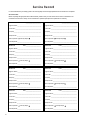
Combustible: Wood
Colors: Metallic Black
Flue Pipe Diameter: 6” (153cm)
Flue Pipe Type: (Standard Single Wall or Double Wall): Black or Blued Steel 2100°F (650°C)
Minimum Chimney Height: 12’ (3.7m)
Maximum Log Length: 17” (432mm)
Electrical 110 Volt, 60 Hz, 31 Watt
Dimensions
Overall: (without Pedestal)
Depth x Width x Height:
23.8” x 30” x 17.75” (605mm x 762mm x 451mm)
Combustion Chamber:
Width x Depth:
12.7” x 11.9” (322mm x 302mm)
Volume:
Cubic Feet:
1.7 cubic feet
Door Opening: Width x Height: 16.8” x 9” (406mm x 228mm)
Pyroceramic Glass Door: (Viewing) Width x Height: 17” x 10” (431mm x 254mm)
Weight (lbs): 433
Specications
Note: Register your product on line at www.usstove.com. See “Limited Warranty” section for specic
warranty information for your new purchase. Save your receipt with your records for any claims.
CONGRATULATIONS!
You’ve purchased a heater from North America’s oldest manufacturer of wood burning products.
By heating with wood you’re helping to CONSERVE ENERGY!
Wood is our only Renewable Energy Resource. Please do your part to preserve our wood supply. Plant at
least one tree each year. Future generations will thank you.
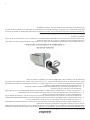
This manual describes the installation and operation of the Vogelzang, VG180L wood heater. This heater
meets the 2015 U.S. Environmental Protection Agency’s crib wood emission limits for wood heaters sold after
May 15, 2015. Under specic test conditions this heater has been shown to deliver heat at rates ranging from
9,550 to 25,696 Btu/hr.
Note: The BTU ratings mentioned above are based on the EPA test protocol burning dimensional Douglas
Fir lumber. Our advertised BTU’s are based on the rst hour of operation at high burn rate burning cordwood.

3
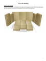
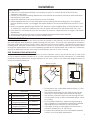
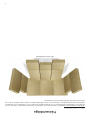
UNPACK AND INSPECT
Remove the packing from the appliance and inspect for any damage. Ensure that the bricks are positioned
correctly and not broken (see illustration for proper brick arrangement). Make sure that the bafe board,
above the air tubes, is in place and undamaged. DO NOT remove the bafe board.
Pre-Assembly
Brick Conguration

4
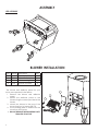
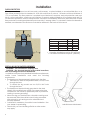
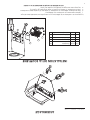
ASSEMBLY
LEG ASSEMBLY
BLOWER INSTALLATION
2
1
4
3
Key Part No. Description Qty.
1 891492 Blower Assembly 1
2 27493 B36 Air Deector 1
3 27494 B-36 Mounting Plate 1
4 83172 #10AX1/2 Screws 4
The blower and deector panel for your
stove come packed in the rebox.
1. Remove the blower and deector
panel.
2. Attach the deector panel to the
blower using the screws provided in the
blower.
3. Attach the blower to the rear of the
stove using four (4) screws (83172).
4. The mounting plate is installed on the
stove from the factory.
� DO NOT REMOVE THE MOUNTING PLATE
FROM THE STOVE THE

5
Installation
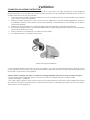
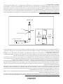
POSITIONING THE STOVE
It is very important to position the stove as close as possible to the chimney, and in an area that will favor
the most efcient heat distribution possible throughout the house. The stove must therefore be installed in
the room where the most time is spent, and in the most spacious room possible. Recall that stoves produce
radiating heat, the heat we feel when we are close to a stove. A stove also functions by convection, that is
through the displacement of hot air accelerated upwards and its replacement with cooler air. If necessary,
the hot air distribution from the stove may be facilitated by the use of a fan or blower.
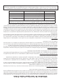
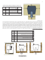
FREE STANDING STOVE INSTALLATION
A stove must never be installed in a hallway or near a staircase, since it may block the way in case of re
or fail to respect required clearances. It is of the utmost importance that the clearances to combustible
materials be strictly adhered to during installation of the stove. Refer to the table and diagrams below for
minimum required clearances.
Back wall / Arrière Mur
Side wall / Paroi Latérale
Side wall / Paroi Latérale
Back wall / Arrière Mur
Side wall / Paroi Latérale
Side wall / Paroi Latérale
Back wall / Arrière Mur
Ceiling / Plafond
Floor Protector / Protection de Plancher
C
B
A
E
E
D
D
F
G
K
H
L
J
M M
Back wall / Arrière Mur
Side wall / Paroi Latérale
Side wall / Paroi Latérale
S d
e
a
/
a
o
at
é a
e
E
E
D
D
Ceiling / Plafond
Back wall / Arrière Mur
Floor Protector / Protection de Plancher
g
F
G
Back wall / Arrière Mur
Side wall / Paroi Latérale
Side wall / Paroi Latérale
S de a / a o até a e
C
B
A
Back wall / Arrière Mur
Side wall / Paroi Latérale
Side wall / Paroi Latérale
Back wall / Arrière Mur
Side wall / Paroi Latérale
Side wall / Paroi Latérale
Back wall / Arrière Mur
Ceiling / Plafond
Floor Protector / Protection de Plancher
C
B
A
E
E
D
D
F
G
K
H
L
J
M M
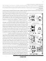
Dimension
A Backwall to Stove 12” (305mm)
B Sidewall to Stove 12” (305mm)
C Sidewall to Flue 13” (330mm)
D
Wall to Stove
(Angled Installation)
8” (203mm)
E
Wall to Flue
(Angled Installation)
8” (203mm)
F Ceiling Height 84” (2133mm)
G Backwall to Flue 13” (330mm)
SAFETY NOTICE
• If this stove is not properly installed, a house re may result. To reduce the risk of re, follow the
installation instructions.
• Consult your municipal building department or re ofcials about permits, restrictions and installations
requirements in your area.
• Use smoke detectors in the room where your stove is installed.
• Smoke expelled from the unit, by either paint curing, opening the fuel loading door, or a negative
pressure inside the home, could trigger the smoke detectors. Mount smoke detectors at least 10’ from
stove
• Never use gasoline, gasoline-type lantern fuel, kerosene, charcoal lighter uid, or similar liquids to start
or “freshen up” a re in this heater. Keep all such liquids well away from the heater while it is in use.
• In the event of a chimney re, push the air control full closed to deprive the re of oxygen. Call the re
department.
• A source of fresh air into the room or space heated shall be provided when required.
• Room heater, solid fuel type, also for use in mobile homes.
• Do not place any combustible material within 4’ (1.2m)
of the front of the unit.
• The clearance between the ue pipe and a wall are
valid only for vertical walls and for vertical ue pipe.
• The chimney connector must not pass through an attic
or roof space, closet or similar concealed space, a oor,
or a ceiling.
• For Canadian installations, where passage through a
wall, or partition of combustible construction is desired,
the installation must conform to CAN/CSA-B365.
• A ue pipe crossing a combustible wall must have a
minimum clearance of 18” (457.2mm).
• To reduce ue clearances from combustible materials,
contact your local safety department.

6
Installation
Back wall / Arrière Mur
Side wall / Paroi Latérale
Side wall / Paroi Latérale
Back wall / Arrière Mur
Side wall / Paroi Latérale
Side wall / Paroi Latérale
Back wall / Arrière Mur
Ceiling / Plafond
Floor Protector / Protection de Plancher
C
B
A
E
E
D
D
F
G
K
H
L
J
M M
FLOOR PROTECTOR
The stove must be placed on solid concrete, solid masonry, or when installed on a combustible oor, on a
Type 2 oor protector listed to standard UL 1618 with a minimum R value of 1.03 and a minimum thickness of
1/2” or equivalent. The oor protector is required to provide heat, live ember, and ash protection and must
be of a non-combustible, continuous solid surface to protect against inltration of live embers and ash. For
UL Listed oor protectors, refer to manufacturers instructions for installation directions. Manufacturers of listed
oor protectors include Imperial Metal Products and Hy-C among others. To calculate R-Values for alternative
methods, see Alternate Floor Protector Calculation Methods in the back of this manual.
Dimension Inch mm
H* Front 9 229
J Flue rear 2 51
K** Left 8 203
L** Right 8 203
M Flue Side 2 51
• Canadian installations require 18” (457mm)
• Canadian installations require 8” (203mm)
SPECIAL MOBILE HOME REQUIREMENTS
WARNING! - Do not install in a sleeping room
CAUTION! - The structural integrity of the mobile home oor,
wall, and ceiling/roof must be maintained.
In addition to the previously detailed installation requirements,
mobile home installations must meet the following
requirements:
• The heater must be permanently attached to the oor.
1. There are two holes in the pedestal base, use 3/8” bolts
through the oor.
2. To attach the leg model use two 3/8-16 UNC bolts
through the oor.
• The heater must be electrically grounded to the steel
chassis of the mobile home with 8 GA copper wire using
a serrated or star washer to penetrate paint or protective
coating to ensure grounding.
• When moving your mobile home, all exterior venting must
be removed while the mobile home is being relocated.
After relocation, all venting must be reinstalled and
securely fastened.
• Outside Air is mandatory for mobile home installation. See
your dealer for purchasing.
• Check with your local building ofcials as other codes
may apply.
Mobile Home Attachment

7
COMBUSTION AIR ASSEMBLY INSTRUCTIONS
This appliance requires a source of combustion air. If your home is of tight construction or has negative
pressure problems, you will need an outside source of air. Below is a list of possible indicators that a source of
outside combustion air may be required.
1. Your stove does not draw steadily, smoke rollout occurs, wood burns poorly, or back-drafts occur whether
or not there is combustion present.
2. Existing fuel-red equipment in the house, such as replaces or other heating appliances, smell, do
not operate properly, suffer smoke roll-out when opened, or back-drafts occur whether or not there is
combustion present.
3. Opening a window slightly on a calm (windless) day alleviates any of the above symptoms.
4. The house is equipped with a well-sealed vapor barrier and tight tting windows and/or has any powered
devices that exhaust house air.
5. There is excessive condensation on windows in the winter.
6. A ventilation system is installed in the house.
Intake Venting Kit Installation
If an outside air intake is required. You have two options. You may cut a rectangular hole in the oor of your
home and the oor protector, or purchase a standard 4” Dryer Vent kit from your local hardware supply store
and install it on the rear of the pedestal.
If using a Intake venting kit, the outlet cover must be of a design that DOES NOT close by means of a ap or trap door.
You must purchase a style that allows a continuous in-ow of air and that has a rodent screen.
“Intake Venting Kit” installation:
First using a pair of pliers or other means, remove the metal plate from the back of the pedestal and bend
the tabs out. Follow the manufacturer’s installation instructions for attaching the dryer vent kit to the home.
Then attach it to the appliance.
Ventilation

8
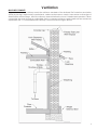
CHIMNEY
Your wood stove may be hooked up with a factory built or masonry chimney, matching the diameter
of the stove exhaust. If you are using a factory built chimney, it must comply with UL 103 or CSA-B365
standard; therefore it must be a Type HT (2100°F). It is extremely important that it be installed according to
the manufacturer’s specications. Take into account the chimney’s location to insure it is not too close to
neighbors or in a valley which may cause unhealthy or nuisance conditions.
If you are using a masonry chimney, it is important that it be built in compliance with the specications of
the National Building Code. It must be lined with re clay bricks, metal or clay tiles sealed together with re
cement. (Round ues are the most efcient).
The interior diameter of the chimney ue must be identical to the stove smoke exhaust. A ue which is too
small may cause draft problems, while a large ue favors rapid cooling of the gas, and hence the build-up of
creosote and the risk of chimney res. Note that it is the chimney and not the stove which creates the draft
effect; your stove’s performance is directly dependent on an adequate draft from your chimney.
Do not connect this unit to a chimney ue serving another appliance.
The following recommendations may be useful for the installation of your chimney:
• It must rise above the roof at least 3’ (0.9m) from the uppermost point of contact.
• The exterior portion should be double or triple wall pipe to ensure proper draft.
• The chimney must exceed any part of the building or other obstruction within a 10’ (3.04m) distance by a
height of 2’ (0.6m).
• Installation of an interior chimney is always preferable to an exterior chimney. The interior chimney will be
hotter than an exterior chimney that is being cooled by the ambient air outside the house. Therefore the
gas which circulates will cool slower, thus reducing the build-up of creosote and the risk of chimney res.
• The draft caused by the tendency for hot air to rise will be increased with an interior chimney.
• Using a re screen at the extremity of the chimney requires regular inspection in order to insure that it is
not obstructed thus blocking the draft, and it should be cleaned when used regularly.
Ventilation

9
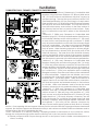
MASONRY CHIMNEY
Ensure that a masonry chimney meets the minimum standards of the National Fire Protection Association
(NFPA) by having it inspected by a professional. Make sure there are no cracks, loose mortar or other signs of
deterioration and blockage. Have the chimney cleaned before the stove is installed and operated. When
connecting the stove through a combustible wall to a masonry chimney, special methods are needed as
explained in the “5.5 Combustible Wall Chimney Connector Pass-Throughs” Section.
Ventilation

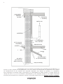
10
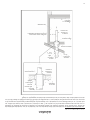
Method A. 12” (304.8 mm) Clearance to Combustible Wall
Member: Using a minimum thickness 3.5” (89 mm) brick and a
5/8” (15.9 mm) minimum wall thickness clay liner, construct a
wall pass-through. The clay liner must conform to ASTM C315
(Standard Specication for Clay Fire Linings) or its equivalent.
Keep a minimum of 12” (304.8 mm) of brick masonry between
the clay liner and wall combustibles. The clay liner shall run
from the brick masonry outer surface to the inner surface of
the chimney ue liner but not past the inner surface. Firmly
grout or cement the clay liner in place to the chimney ue
liner.
Method B. 9” (228.6 mm) Clearance to Combustible Wall
Member: Using a 6” (152.4 mm) inside diameter, listed, factory-
built Solid-Pak chimney section with insulation of 1” (25.4 mm)
or more, build a wall pass-through with a minimum 9” (228.6
mm) air space between the outer wall of the chimney length
and wall combustibles. Use sheet metal supports fastened
securely to wall surfaces on all sides, to maintain the 9” (228.6
mm) air space. When fastening supports to chimney length,
do not penetrate the chimney liner (the inside wall of the
Solid-Pak chimney). The inner end of the Solid-Pak chimney
section shall be ush with the inside of the masonry chimney
ue, and sealed with a non-water soluble refractory cement.
Use this cement to also seal to the brick masonry penetration.
Method C. 6” (152.4 mm) Clearance to Combustible Wall
Member: Starting with a minimum 24 gauge (.024” [.61 mm])
6” (152.4 mm) metal chimney connector, and a minimum 24
gauge ventilated wall thimble which has two air channels of
1” (25.4 mm) each, construct a wall pass-through. There shall
be a minimum 6” (152.4) mm separation area containing
berglass insulation, from the outer surface of the wall thimble
to wall combustibles. Support the wall thimble, and cover
its opening with a 24-gauge minimum sheet metal support.
Maintain the 6” (152.4 mm) space. There should also be a
support sized to t and hold the metal chimney connector.
See that the supports are fastened securely to wall surfaces
on all sides. Make sure fasteners used to secure the metal
chimney connector do not penetrate chimney ue liner.
Method D. 2” (50.8 mm) Clearance to Combustible Wall
Member: Start with a solid-pak listed factory built chimney
section at least 12” (304 mm) long, with insulation of 1” (25.4
mm) or more, and an inside diameter of 8” (2 inches [51 mm]
larger than the 6” [152.4 mm] chimney connector). Use this
as a pass-through for a minimum 24-gauge single wall steel
chimney connector. Keep solid-pak section concentric with
and spaced 1” (25.4 mm) off the chimney connector by
way of sheet metal support plates at both ends of chimney
section. Cover opening with and support chimney section on both sides with 24 gauge minimum sheet metal
supports. See that the supports are fastened securely to wall surfaces on all sides. Make sure fasteners used to
secure chimney ue do not penetrate ue liner.
NOTE: Connectors to a masonry chimney, excepting method B, shall extend in one continuous section
through the wall pass-through system and the chimney wall, to but not past the inner ue liner face.
A chimney connector shall not pass through an attic or roof space, closet or similar concealed space, or
a oor, or ceiling.
COMBUSTIBLE WALL CHIMNEY CONNECTOR PASS-THROUGHS
Ventilation

11
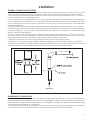
CHIMNEY CONNECTOR (STOVE PIPE)
Your chimney connector and chimney must have the same diameter as the stove outlet. If this is not the
case, we recommend you contact your dealer in order to insure there will be no problem with the draft.
The stove pipe must be made of aluminized or cold roll steel with a minimum thickness of 0.021” or 0.53 mm.
It is strictly forbidden to use galvanized steel.
Your stove pipe should be assembled in such a way that the male section (crimped end) of the pipe faces
down. Attach each of the sections to one another with three equidistant metal screws. Seal the joints with
furnace cement. The stove pipe must be fastened to the stove by at least two screws or other equivalent
mechanical methods.
The pipe must be short and straight. All sections installed horizontally must slope at least 1/4 inch per foot,
with the upper end of the section toward the chimney. Any installation with a horizontal run of stove pipe must
conform to NFPA 211. You may contact NFPA (National Fire Protection Association) and request the latest
edition of the NFPA Standard 211.
To insure a good draft, the total length of the stove pipe should never exceed 8’ to 10’ (2.4m to 3.04 m).
(Except for cases of vertical installation, cathedral-roof style where the smoke exhaust system can be much
longer and connected without problem to the chimney at the ceiling of the room).
There should never be more than two 90 degrees elbows in the smoke exhaust system.
Installation of a “barometric draft stabilizer” (replace register) on a smoke exhaust system is prohibited.
Furthermore, installation of a draft damper is not recommended. With a controlled combustion wood stoves
the draft is regulated upon intake of the combustion air in the stove and not at the exhaust.
To
Appliance
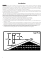
IMPORTANCE OF PROPER DRAFT
Draft is the force which moves air from the appliance up through the chimney. The amount of draft in your
chimney depends on the length of the chimney, local geography, nearby obstructions and other factors. Too
much draft may cause excessive temperatures in the appliance. Inadequate draft may cause backpufng
into the room and ‘plugging’ of the chimney.
Inadequate draft will cause the appliance to leak smoke into the room through appliance and chimney
connector joints. An uncontrollable burn or excessive temperature indicates excessive draft.
Ventilation

12
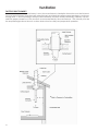
FACTORY BUILT CHIMNEY
When a metal prefabricated chimney is used, the manufacturer’s installation instructions must be followed.
You must also purchase (from the same manufacturer) and install the ceiling support package or wall pass-
through and “T” section package, restops (where needed), insulation shield, roof ashing, chimney cap, etc.
Maintain proper clearance to the structure as recommended by the manufacturer. The chimney must be
the required height above the roof or other obstructions for safety and proper draft operation.
Ventilation

13
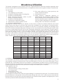
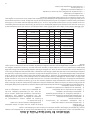
TYPE WEIGHT
(LBS. CU. FT., DRY)
PER CORD EFFICIENCY
RANKING
SPLITS MILLIONS
BTU’s/CORD
Hickory 63 4500 1.0 Well 31.5
White Oak 48 4100 .9 Fair 28.6
Red Oak 46 3900 .8 Fair 27.4
Beech 45 3800 .7 Hard 26.8
Sugar Maple 44 3700 .6 Fair 26.2
Black Oak 43 3700 .6 Fair 25.6
Ash 42 3600 .5 Well 25.0
Yellow Birch 40 3400 .4 Hard 23.8
Red Maple 38 3200 .3 Fair 22.6
Paper Birch 37 3100 .3 Easy 22.1
Elm/Sycamore 34 2900 .2 Very Difcult 20.1
Red Spruce 29 1800 .1 Easy 16.1
Woodstove Utilization
It is EXTREMELY IMPORTANT that you use DRY WOOD only in your wood oven. The wood should have dried for
9 to 15 months, such that the humidity content (in weight) is reduced below 20% of the weight of the log. It is
very important to keep in mind that even if the wood has been cut for one, two or even more years, it is not
necessarily dry, if it has been stored in poor conditions. Under extreme conditions it may rot, instead of drying.
This point cannot be over stressed; the vast majority of the problems related to the operation of a wood oven
is caused by the fact that the wood used was too damp or has dried in poor conditions.
These problems can be:
• Ignition problems
• Creosote build-up causing chimney res
• Low energy yield
• Blackened windows
• Incomplete log combustion
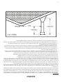
Smaller pieces of wood will dry faster. All logs exceeding 6” in diameter should be split. The wood should not
be stored directly on the ground. Air should circulate through the cord. A 24” to 48” air space should be left
between each row of logs, which should be placed in the sunniest location possible. The upper layer of wood
should be protected from the elements but not the sides.
This heater is designed to burn natural wood only. Higher efciencies and lower emissions generally result
when burning air dried seasoned hardwoods, as compared to softwoods or to green or freshly cut hardwoods.
DO NOT BURN:
1. Garbage;
2. Lawn clippings or yard waste;
3. Materials containing rubber, including tires;
4. Materials containing plastic;
5. Waste petroleum products, paints or paint
thinners, or asphalt products;
6. Materials containing asbestos;
7. Construction or demolition debris;
8. Railroad ties or pressure-treated wood;
9. Manure or animal remains;
10. Salt water driftwood or other previously salt
water saturated materials;
11. Unseasoned wood; or
12. Paper products, cardboard, plywood, or
particleboard. The prohibition against burning
these materials does not prohibit the use of re
starters made from paper, cardboard, saw dust,
wax and similar substances for the purpose of
starting a re in an affected wood heater.
Burning these materials may result in release of toxic fumes or render the heater ineffective and cause
smoke. Dead wood lying on the forest oor should be considered wet, and requires full seasoning time.
Standing dead wood can usually be considered to be about 2/3 seasoned. Splitting and stacking wood
before it is stored accelerates drying time. Storing wood on an elevated surface from the ground and under
a cover or covered area from rain or snow also accelerates drying time. A good indicator if wood is ready to
burn is to check the piece ends. If there are cracks radiating in all directions from the center then the wood
should be dry enough to burn. If your wood sizzles in the re, even though the surface is dry, it may not be
fully cured, and should be seasoned longer. Waste and other ammable materials should not be burned in
your oven. Any type of wood may be used in your oven, but specic varieties have better energy yields than
others. Please consult the following table in order to make the best possible choice.

14
Woodstove Utilization
TESTING YOUR WOOD
When the oven is thoroughly warmed, place one piece of split wood (about ve inches in diameter) parallel
to the door on the bed of red embers.
Keep the air control full open by pulling on it and close the door. If ignition of the piece is accomplished
within 90 seconds from the time if was placed in the oven, your wood is correctly dried. If ignition takes longer,
your wood is damp.
If your wood hisses and water or vapor escapes at the ends of the piece, your wood is soaked or freshly cut.
Do not use this wood in your oven. Large amounts of creosote could be deposited in your chimney, creating
potential conditions for a chimney re.
TAMPER WARNING
This wood heater has a manufacturer-set minimum low burn rate that must not be altered. It is against
federal regulations to alter this setting or otherwise operate this wood heater in a manner inconsistent with
operating instructions in this manual.
THE FIRST FIRES
The fresh paint on your stove needs to be cured to preserve its quality. Once the fuel charge is properly
ignited, only burn small res in your stove for the rst four hours of operation. Never open the air control more
than necessary to achieve a medium burn rate.
Make sure that there’s enough air circulation while curing the stove. The odors could be smelled during the
3 or 4 rst res. Never start your stove outside. You will not be able to see if you are over heating.
IGNITION
After making sure that the stove air intake controls are fully open (completely pull-out towards you), place
several rumpled sheets of paper in the center of the combustion chamber. Place 8 to 10 pieces of small dry
kindling wood over the paper in the form of a tent. You may also place a few pieces of heating wood, but
choose the smaller ones. No chemical product should be used to light the re.
Before igniting the paper and kindling wood, it is recommended that you warm up the chimney. This is done
in order to avoid back draft problems often due to negative pressure in the house. If such is the case, open a
window slightly near the stove and twist together a few sheets of newspaper into a torch. Light up this paper
torch and hold it as close as possible to the mouth of the pipe inside the combustion chamber to warm up
the chimney. Once the updraft movement is initiated, you are ready to ignite the stove by lighting the paper
and kindling wood inside the combustion chamber.
When you have achieved a good bed of hot embers, we recommend the following burn procedures:
CAUTION: Never alter the damper slide or the adjustment range to increase ring for any reason. Doing so
could result in heater damage and will void your warranty.
CAUTIONS:
• Ashes could contain hot embers even after two days without operating the stove.
• The ash pan can become very hot. Wear gloves to prevent injury.
• Never burn the stove with the stove door or ash clean out opening unsealed . This would result in over
ring the stove. Damage to the stove and even house re may result.
Primary Air Settings
(Slide Damper is located in center of stove under hearth plate)
(Damper Adjustment: Pulling out on damper decreases air)
Burn Rate Adjust Damper from fully closed Burn Time
Low 3/16” (4.7mm) @ 30 minutes
Medium - Low 1/4” (6.4mm) @ 30 minutes
Medium - High 9/32” (7.1mm) @ 30 minutes
High 3/4” (19mm) all minutes

15
The amount of visible smoke being produced can be an effective method of determining how efciently
the combustion process is taking place at the given settings. Visible smoke consist of unburned fuel and
moisture leaving your stove. Learn to adjust the air settings of your specic unit to produce the smallest
amount of visible smoke. Wood that has not been seasoned properly and has a high wood moisture content
will produce excess visible smoke and burn poorly.
WARNINGS
• NEVER OVERFIRE YOUR STOVE. IF ANY PART OF THE STOVE STARTS TO GLOW RED, OVER FIRING IS
HAPPENING. READJUST THE AIR INTAKE CONTROL AT A LOWER SETTING.
• THE INSTALLATION OF A LOG CRADLE OR GRATES IS NOT RECOMMENDED IN YOUR WOOD STOVE. BUILD
FIRE DIRECTLY ON FIREBRICK.
• NEVER PUT WOOD ABOVE THE FIREBRICK LINING OF THE FIREBOX.
• ATTEMPTS TO ACHIEVE HEAT OUTPUT RATES THAT EXCEED HEATER DESIGN SPECIFICATIONS CAN RESULT IN
PERMANENT DAMAGE TO THE HEATER.
OPERATION
Controlled combustion is the most efcient technique for wood heating because it enables you to select
the type of combustion you want for each given situation. The wood will burn slowly if the wood stove air
intake control is adjusted to reduce the oxygen supply in the combustion chamber to a minimum. On the
other hand, wood will burn quickly if the air control is adjusted to admit a larger quantity of oxygen in the
combustion chamber. The air intake control on your stove is very simple. If you pull on it out completely
towards you, it is fully open. If you push on it until it stops the combustion air is reduced to a minimum. Real
operating conditions may give very different results than those obtained during testing according to the
species of wood used, its moisture content, the size and density of the pieces, the length of the chimney,
altitude and outside temperature.
Efciencies can be based on either the lower heating value (LHV) or the higher heating value (HHV) of
the fuel. The lower heating value is when water leaves the combustion process as a vapor, in the case of
woodstoves the moisture in the wood being burned leaves the stove as a vapor. The higher heating value
is when water leaves the combustion process completely condensed. In the case of woodstoves this would
assume the exhaust gases are room temperature when leaving the system, and therefore calculations using
this heating value consider the heat going up the chimney as lost energy. Therefore, efciency calculated
using the lower heating value of wood will be higher than efciency calculated using the higher heating
value. In the United States all woodstove efciencies should be calculated using the higher heating value.
The best way to achieve optimum efciencies is to learn the burn characteristic of you appliance and
burn well-seasoned wood. Higher burn rates are not always the best heating burn rates; after a good re is
established a lower burn rate may be a better option for efcient heating. A lower burn rate slows the ow of
usable heat out of the home through the chimney, and it also consumes less wood.
The top down method of re building is recommended for this appliance. After making sure that the stove
air intake controls are fully open (completely pull-out towards you), Place the largest pieces of wood on the
bottom, laid in parallel and close together. Smaller pieces are placed in a second layer, crossways to the rst.
A third layer of still smaller pieces is laid crossways to the second, this time with some spaces between. Then
a fourth layer of loose, small kindling and twisted newspaper sheets tops off the pile.
RELOADING
Once you have obtained a good bed of embers, you should reload the unit. In order to do so, open the air
controls to maximum a few seconds prior to opening the stove’s door. Then proceed by opening the door
very slowly; open it one or two inches for 5 to 10 seconds, before opening it completely to increase the draft
and thus eliminate the smoke which is stagnant in a state of slow combustion in the stove. Then bring the red
embers to the front of the stove and reload the unit.
For optimal operation of your wood stove, we recommend you to operate it with a wood load approximately
equivalent to the height of re bricks.It is important to note that wood combustion consumes ambient oxygen
in the room. In the case of negative pressure, it is a good idea to allow fresh air in the room, either by opening
a window slightly or by installing a fresh air intake system on an outside wall.
Woodstove Utilization

16
It is strongly recommended that ashes in the metal container are taken outside immediately, and are not
stored within your home.
Creosote - Formation and Need for Removal when wood is burned slowly, it produces tar and other organic
vapors, which combine with expelled moisture to form creosote. The creosote vapors condense in the
relatively cool chimney ue of a slow-burning re. As a result, creosote residue accumulates on the ue lining.
When ignited, this creosote makes an extremely hot re. The chimney connector and chimney should be
inspected at least once every two months during the heating season to determine if a creosote build-up has
occurred. If creosote has accumulated (3mm or more), it should be removed to reduce the risk of a chimney
re.
We strongly recommend that you install a magnetic thermometer on your smoke exhaust pipe, approximately
18” above the stove. This thermometer will indicate the temperature of your gas exhaust fumes within the
smoke exhaust system. The ideal temperature for these gases is somewhere between 275°F and 500°F. Below
these temperatures, the build-up of creosote is promoted. Above 500 degrees, heat is wasted since a too
large quantity is lost into the atmosphere.
• To Prevent Creosote Build Up: Always Burn Dry Wood. This Allows Clean Burns And Higher Chimney
Temperatures, Therefore Less Creosote Deposit.
Leave the air control full open for about 5 min. every time you reload the stove to bring it back to proper
operating temperatures. The secondary combustion can only take place if the rebox is hot enough.
Always check for creosote deposit once every two months and have your chimney cleaned at least once
a year.
If a chimney or creosote re occurs, close all dampers immediately. Wait for the re to go out and the heater
to cool, then inspect the chimney for damage. If no damage results, perform a chimney cleaning to ensure
there is no more creosote deposits remaining in the chimney.
ASH DISPOSAL
Whenever ashes get 3 to 4 inches deep in your rebox or ash pan, and when the re has burned down and
cooled, remove excess ashes. Leave an ash bed approximately 1 inch deep on the rebox bottom to help
maintain a hot charcoal bed.
Ashes should be placed in a metal container with a tight-tting lid. The closed container of ashes should
be placed on a noncombustible oor or on the ground, away from all combustible materials, pending nal
disposal. The ashes should be retained in the closed container until all cinders have thoroughly cooled.
SMOKE AND CO MONITORS
Burning wood naturally produces smoke and carbon monoxide(CO) emissions. CO is a poisonous gas when
exposed to elevated concentrations for extended periods of time. While the modern combustion systems in
heaters drastically reduce the amount of CO emitted out the chimney, exposure to the gases in closed or
conned areas can be dangerous. Make sure your stove gaskets and chimney joints are in good working
order and sealing properly to ensure unintended exposure. It is recommended that you use both smoke and
CO monitors in areas having the potential to generate CO.
OPERATIONAL TIPS
• Operational Tips for Good, Efcient, and Clean Combustion
• Get the appliance hot and establish a good coal bed before adjusting to a low burn rate (this may take
30 minutes or more depending on your wood)
• Use smaller pieces of wood during start-up and a high burn rate to increase the stove temperature
• Be considerate of the environment and only burn dry wood
• Burn small, intense res instead of large, slow burning res when possible
• Learn your appliance’s operating characteristics to obtain optimum performance
• Burning unseasoned wet wood only hurts your stoves efciency and leads to accelerated creosote
buildup in your chimney
Woodstove Utilization

17
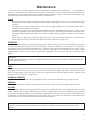
Your wood stove is a high efciency stove and therefore requires little maintenance. It is important to
perform a visual inspection of the stove every time it is emptied, in order to insure that no parts have been
damaged, in which case repairs must be performed immediately. Inspect and clean the chimney and
connector pipe periodically for creosote buildup or obstructions.
GLASS
• Inspect and clean the glass regularly in order to detect any cracks. If you spot one, turn the stove off
immediately. Do not abuse the glass door by striking or slamming shut. Do not use the stove if the glass
is broken.
• If the glass on your stove breaks, replace only with the glass supplied from your heater dealer. Never
substitute other materials for the glass.
• To replace the glass, remove the screws retaining the glass mouldings inside the door. Remove the
mouldings and replace the damaged piece with a new one. Perform the procedure backwards after
replacing. When replacing the glass, you should change the glass gasket to make sure you keep it
sealed.
• Never wash the glass with a product that may scratch. Use a specialized product, available in the
stores where wood stoves are sold. The glass should be washed only when cold.
GASKETING
It is recommended that you change the door gasket (which makes your stove door air tight) once a year,
in order to insure good control over the combustion, maximum efciency and security. To change the
door gasket, simply remove the damaged one. Carefully clean the available gasket groove, apply a high
temperature silicone sold for this purpose and install the new gasket. You may light up your stove again
approximately 24 hours after having completed this operation. This unit’s door uses a 3/4” diameter rope
gasket.
WARNING:
NEVER OPERATE THE STOVE WITHOUT A GASKET OR WITH A BROKEN ONE. DAMAGE TO THE STOVE OR EVEN
HOUSE FIRE MAY RESULT.
PAINT
Only clean your stove with a dry soft cloth that will not harm the paint nish. If the paint becomes scratched or
damaged, it is possible to give your wood stove a brand new look by repainting it with a 1200° F heat resistant
paint. For this purpose, simply scrub the surface to be repainted with ne sand paper, clean it properly, and
apply thin coats (2) of paint successively.
BLOWER (IF EQUIPPED)
The blower needs to be removed and air blown clean. Make sure the blades do not have build up.
FIREBRICK
The rebrick should be cleaned and inspected as necessary. Replace any damaged or broken brick.
AIR TUBES
The secondary air tubes must be cleaned with a wire brush. If debris remains in holes lightly tap with a wooden
stick to remove. The air tubes assembled in this unit are designed to provide an accurate mix of secondary
air to insure the highest efciency. Any damage or deterioration of these tubes may reduce the efciency of
combustion. The air tubes are held in position by either screws or snap pins. Locate these to either side of the
tube and remove to allow the tube to be removed and replaced.
Maintenance
This wood heater needs periodic inspection and repair for proper operation. It is against federal
regulations to operate this wood heater in a manner inconsistent with operating instructions in this
manual.

18
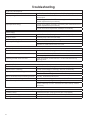
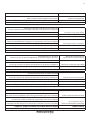
High Fuel Consumption
Possible Cause Possible Remedies (Unplug blower rst if equipped)
Improper regulation of draft or air inlet Close air inlet control as much as possible to maintain desired
heat output.
Check all gaskets, reinstall if necessary (see maintenance for
gasket replacement procedure).
Improper door tting Check door gasket, reinstall if necessary (see maintenance for
gasket replacement procedure).
Check door latch adjustment. Readjust if necessary.
Back Pufng
Possible Cause Possible Remedies (Unplug blower rst if equipped)
Gusts of wind. Chimney may need wind diverter.
2-10-3 rule not properly maintained. Raise chimney to appropriate height.
Chimney Blockage. Smoke shelf in chimney is lled with creosote, soot and ash.
Tree limb or other obstruction too close.
Persistent soot, creosote or ash build up in chimney
Possible Cause Possible Remedies (Unplug blower rst if equipped)
Cool exhaust ue gasses. Use double or triple wall external chimney.
Burning unseasoned / wet wood Use dry, seasoned hardwood.
Smoke rolls out when feed or ash doors are opened
Possible Cause Possible Remedies (Unplug blower rst if equipped)
Wind Gusts blowing down the chimney. Smoke shelf in chimney is lled with creosote, soot and ash.
Chimney may need wind diverter.
Opening heater door too soon. Open air control, crack door for 5-10 seconds before fully
opening door.
Low Heat Output
Possible Cause Possible Remedies (Unplug blower rst if equipped)
Obstruction in chimney. Check for blockage in chimney, remove if necessary.
Improperly sealed venting. Check all gasketing, replace if necessary.
Check exhaust venting seals, reseal if necessary.
Wet or unseasoned wood being burned. Burn dry, seasoned hard wood.
Improper wood loading. Load wood according to directions under utilization.
Poor chimney draft. Improper chimney height or wrong size ue in use.
Inspect chimney for soot, creosote and ash buildup, clean if
necessary.
Troubleshooting

19
2
1
3
4
6
7
8
9
5
9
8
1 2 3
4
5
11
10
7
6
1
2
3
4
8
6
5
7
9
2
1
3
4
6
7
8
9
5
9
8
1 2 3
4
5
11
10
7
6
1
2
3
4
8
6
5
7
9
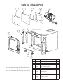
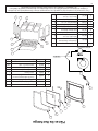
Key Part No. Description Qty.
1 26699 Cover Plate, Access Panel 1
2 88206 Access Panel Insulation 1
3 27493 B36 Air Deector 1
4 27494 B-36 Mounting Plate 1
5 891492 Blower Assembly (B36) 1
6 26410 Tensioner, Damper Rod 2
7 26708 Damper Rod 1
8 892260 Trim, Stainless (21”) 1
9 892334 10.00 X 3.50 Glass 2
10 26683 Window Cover 2
11 69953 Door Assembly 1
In order to maintain warranty, components
must be replaced using original manufacturers
parts purchased through your dealer or directly
from the appliance manufacturer. Use of third
party components will void the warranty.
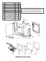
Parts List / Repair Parts

20
Wiring Schematic
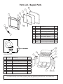
Key Part No. Description Qty.
1 891135 Handle, Spring (Lg-Nickel) 1
2 892333 4" Handle 1
3 40585 Large Viewing Glass Door 1
4 26314 Gasket Clamp 1
5 26312 Glass Clamp, Side 4
6 26311 Glass Clamp, Bottom 2
7 88174 Glass Gasket (1 x 1/8) 4.4ft
8 892204 Glass 1
9 88082 3/4 Round Rope Gasket-Blk 4.7ft
Key Part No. Description Qty.
1 88198 Ceramic Fiber Board Top 1
2 86726 Tube (Ø5/32) , Secondary Air 2
3 892422 Back Panel, Firebox 1
4 26706 Right Brick Retainer 1
5 89066 Firebrick (4-1/2 X 9) 5
6 891530 Firebrick (4.5 X 7.5 X 1.25) 2
7 27338 Firebrick (3 X 4-1/2) 3
8 26705 Left Brick Retainer 1
9 86727 Tube (Ø3/16) , Secondary Air 1
2
1
3
4
6
7
8
9
5
9
8
1 2 3
4
5
11
10
7
6
1
2
3
4
8
6
5
7
9
2
1
3
4
6
7
8
9
5
9
8
1 2 3
4
5
11
10
7
6
1
2
3
4
8
6
5
7
9
In order to maintain warranty, components must be replaced using original manufacturers parts
purchased through your dealer or directly from the appliance manufacturer. Use of third party
components will void the warranty.
Parts List / Repair Parts
La page est en cours de chargement...
La page est en cours de chargement...
La page est en cours de chargement...
La page est en cours de chargement...
La page est en cours de chargement...
La page est en cours de chargement...
La page est en cours de chargement...
La page est en cours de chargement...
La page est en cours de chargement...
La page est en cours de chargement...
La page est en cours de chargement...
La page est en cours de chargement...
La page est en cours de chargement...
La page est en cours de chargement...
La page est en cours de chargement...
La page est en cours de chargement...
La page est en cours de chargement...
La page est en cours de chargement...
La page est en cours de chargement...
La page est en cours de chargement...
La page est en cours de chargement...
La page est en cours de chargement...
La page est en cours de chargement...
La page est en cours de chargement...
La page est en cours de chargement...
La page est en cours de chargement...
La page est en cours de chargement...
La page est en cours de chargement...
-
 1
1
-
 2
2
-
 3
3
-
 4
4
-
 5
5
-
 6
6
-
 7
7
-
 8
8
-
 9
9
-
 10
10
-
 11
11
-
 12
12
-
 13
13
-
 14
14
-
 15
15
-
 16
16
-
 17
17
-
 18
18
-
 19
19
-
 20
20
-
 21
21
-
 22
22
-
 23
23
-
 24
24
-
 25
25
-
 26
26
-
 27
27
-
 28
28
-
 29
29
-
 30
30
-
 31
31
-
 32
32
-
 33
33
-
 34
34
-
 35
35
-
 36
36
-
 37
37
-
 38
38
-
 39
39
-
 40
40
-
 41
41
-
 42
42
-
 43
43
-
 44
44
-
 45
45
-
 46
46
-
 47
47
-
 48
48


United States Stove VG180L Le manuel du propriétaire
- Catégorie
- Poêle à bois
- Taper
- Le manuel du propriétaire
dans d''autres langues
Documents connexes
-
United States Stove AWC21M Le manuel du propriétaire
-
-
-
-
-
Autres documents
-
Ashley AWC31M Mode d'emploi
-
Ashley Hearth Products AW40 Le manuel du propriétaire
-
United States Stove Company VG3200-P Le manuel du propriétaire
-
US Stove Company US2500E-BP Le manuel du propriétaire
-
Vogelzang Plate Steel Wood Stove Le manuel du propriétaire
-
Ashley Hearth Products AW2020E Manuel utilisateur
-
-
 Nectre N550W Guide d'installation
-
 Regency Fireplace Products Classic F2450 Le manuel du propriétaire

