United States Stove Company TH-100 Le manuel du propriétaire
- Catégorie
- Poêle à bois
- Taper
- Le manuel du propriétaire

853954-4305L
Report Number: F22-781
Tested Per EPA Methods 28R and ASTME2515
and ASTME2780 and CSAB415.1
Certified to UL 1482-2022 and
ULC-S627:2023
Mobile home/transportable building approved
TH100
* All Pictures In This Manual Are For Illustrative Purposes Only. Actual Product May Vary.
© 2023 United States Stove Company, 227 Industrial Park Rd., South Pittsburg, TN 37380 Ph. 800-750-2723
THIS MANUAL IS SUBJECT TO CHANGE WITHOUT NOTICE.
Owner’s Instruction and Operation Manual
SAFETY NOTICE: If this heater is not properly installed, a house fire may result. For
your safety, follow the installation instructions. Never use make-shift compromises
during the installation of this heater. Contact local building or fire ocials about
permits, restrictions and installation requirements in your area. NEVER OPERATE
THIS PRODUCT WHILE UNATTENDED.
CAUTION! Please read this entire manual before you install or use your new room
heater. Failure to follow instructions may result in property damage, bodily injury, or
even death. Improper Installation Will Void Your Warranty!
Save These Instructions In A Safe Place For Future Reference.
CALIFORNIA PROPOSITION 65 WARNING:
This product can expose you to chemicals including carbon
monoxide, which is known to the State of California to cause
cancer, birth defects, and/or other reproductive harm. For
more information, go to www.P65warnings.ca.gov
U.S. Environmental Protection Agency
Certified to comply with 2020 particulate
emissions standards.
Model Number:

2
© 2023 United States Stove Company
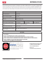
This manual describes the installation and operation of the USSC TH100 wood heater. This heater meets the 2020
U.S. Environmental Protection Agency’s cordwood emission limits for wood heaters sold after May 15, 2020. Under
specific test conditions this heater has been shown to deliver heat at rates ranging from 10,652 to 26,028 Btu/hr with
1.7 g/hr and 75% eciency. Note: The BTU ratings mentioned above are based on the EPA test protocol under specific
test conditions. Our advertised BTU’s are based on the first hour of operation at high burn rate burning dry cordwood.
Combustible: Wood
Colors: Black
Flue Pipe Diameter: 6” (153 mm)
Flue Pipe Type: Black or Blued Steel 2100°F (650°C)
Minimum Chimney Height: 12’ (3.7 m)
Maximum Log Length: 11” (279 mm)
Electrical: 120VAC, 0.55A, 60Hz
Dimensions
DEPTH WIDTH HEIGHT
Overall: Depth x Width x Height: 13” (330 mm) 16.4” (417 mm) 26.75” (680 mm)
Combustion Chamber: Width x
Depth: 11.25” x 8.5” (286 mm X 216 mm)
Firebox Volume: Cubic Feet: .59 cubic feet
Door Opening: Width x Height: 9.6” x 9.6” (244 mm X 244 mm)
Pyroceramic Glass Door: (Viewing)
Width x Height: 9.5” x 10.5” (241 mm X 267 mm)
INTRODUCTION
CAUTIONS:
• HOT WHILE IN OPERATION. KEEP CHILDREN, CLOTHING AND FURNITURE AWAY. CONTACT MAY CAUSE
SKIN BURNS.
• DO NOT USE CHEMICALS OR FLUIDS TO IGNITE THE FIRE.
• DO NOT LEAVE THE STOVE UNATTENDED WHEN THE DOOR IS SLIGHTLY OPENED.
• DO NOT BURN GARBAGE, FLAMMABLE FLUID SUCH AS GASOLINE, NAPHTHA OR MOTOR OIL.
• DO NOT CONNECT TO ANY AIR DISTRIBUTION DUCT OR SYSTEM.
• ALWAYS CLOSE THE DOOR AFTER THE IGNITION.
For Customer Service, please call:
1-800-750-2723 Ext 5050 or;
Text to 423-301-5624 or;
Email us at:
customerservice@usstove.com
Note: Register your product online at
www.usstove.com or download the free
app today. This app is available only
on the App Store for iPhone and iPad.
Search US Stove. Save your receipt with
your records for any claims.

© 2023 United States Stove Company
3
INSTALLATION CHECKLIST
Your Wood Stove should be installed by a qualified installer only. An NFI qualified Installer can be found at;
www.nficertified.org/public/find-an-nfi-pro/
CUSTOMER SERVICE
1-800-750-2723 ext 5050
Text to 423-301-5624
Email to: Customerservice@usstove.com
COMMISSIONING CHECKLIST
This checklist is to be completed in full by the qualified person who installs this unit. Keep this page for future reference.
Failure to install and commission according to the manufacturer’s instructions and complete this checklist will
invalidate the warranty.
Please Print
Customer Name: Telephone Number:
Address:
Model:
Serial Number:
Installation Company Name: Phone Number:
Installation Technician’s Name: License Number:
DESCRIPTION OF WORK
Location of installed appliance: __________________________________________________________________________________
Chimney System: New Chimney System Yes No If yes, Brand _________________________________________
If no, Date of inspection of the existing chimney system: __________________________________________________________
COMMISSIONING
Confirm Hearth Pad Installation as per Installation Instructions ...................................................................................................
Confirm proper placement of internal parts ..........................................................................................................................................
Check soundness of door gasket and door seals .................................................................................................................................
Confirm clearances to combustibles as per installation instructions in this manual ..............................................................
Check the operations of the air controls .................................................................................................................................................
Confirm all flue pipe and chimney system are secure and sealed ..................................................................................................
Confirm the stove properly drafts when fired .......................................................................................................................................
Check to ensure a CO alarm is installed as per local building codes and is functional ............................................................
Explain the safe operation, proper fuel usage, cleaning and routine maintenance requirements ........................................
Declaration of Completion: As the qualified person responsible for the work described above, I confirm that the appliance
as associated work has been installed as per manufacturer’s instructions and following any applicable building and
installation codes.
Signed: ______________________________________ Print Name: __________________________________Date: ______________
Home Owner: RETAIN THIS INFORMATION FOR FUTURE REFERENCE

4
© 2023 United States Stove Company
ASSEMBLY INSTRUCTIONS
TOOLS AND MATERIALS
You will need the following items for installation:
• A drill phillips head screwdriver.
• A ratchet wrench with a 7/16” and 1/2” sockets or
wrenches to install flue collar and leg assembly to the
unit.
• An 1/8” drill bit to drill pilot holes into the vent pipe for
securing each section.
• A non-combustible floor protector as specified in this
manual.
• All chimney and chimney connector components for
your particular chimney installation.
• Additional items for Mobile home/transportable
buildings may be needed. See “For use in Mobile home/
transportable buildings” section of this manual.
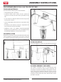
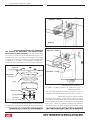
LEG INSTALLATION
Carefully lay the heater on its back and install all four legs
with the hardware provided. Note: To prevent scratching
lay cardboard down before placing the heater on its back.
50FAK AIR INTAKE
Attach the 50FAK air intake using the hardware provided.
BLOWER ASSEMBLY (INCLUDED)
The blower assembly must be disconnected from
the source of electrical supply before attempting the
installation. The blower assembly is intended for use only
with a stove that is marked to indicate such use. Do not
route the supply cord near or across hot surfaces! Fix the
assembly to the back of the stove with the four screws
provided. To install:
FOR CUSTOMER SERVICE CALL: 8007502723 EXT 5050

© 2023 United States Stove Company
5
ASSEMBLY INSTRUCTIONS
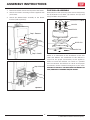
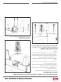
1. Remove the blank from the back panel of the heater.
2. Attach the blower mounting bracket supplied with
your heater.
3. Attach the CB36 blower assembly to the blower
bracket (sold separately).
Step 1: Remove
Step 2: Attach
Step 3: Attach
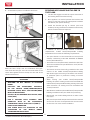
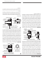
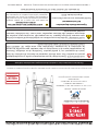
FLUE COLLAR ASSEMBLY
Mount the flue collar to the top of the unit as shown using
the (3) 5/16-18 x 1-1/2 bolts, (3) washers, and (3) weld
tabs provided in the parts box.
5/16-18 x 1-1/2 BOLT
DIFFUSER
WASHER
GASKET
HEATER TOP
WELD TAB
Above is an illustration of the installation of the flue
collar and diuser. The installation of this diuser is
critical for the proper functionality of this appliance.
Failure to install this diuser can result in a possible
over fire situation. This diuser is critical to the proper
functionality for the cleanest burning fires in your stove.
FAILURE TO INSTALL THE DIFFUSER CAN RESULT IN
FIRE, PROPERTY DAMAGE AND/OR DEATH.
Optional

6
© 2023 United States Stove Company
INSTALLATION
SAFETY NOTICE
• DO NOT INSTALL IN AN ALCOVE
• THIS ROOM HEATER SHALL NOT BE INSTALLED
IN A FACTORY-BUILT FIREPLACE.
• IF THIS STOVE IS NOT PROPERLY INSTALLED,
A HOUSE FIRE MAY RESULT. TO REDUCE THE
RISK OF FIRE, FOLLOW THE INSTALLATION
INSTRUCTIONS.
• CONSULT YOUR MUNICIPAL BUILDING
DEPARTMENT OR FIRE OFFICIALS ABOUT
PERMITS, RESTRICTIONS AND INSTALLATIONS
REQUIREMENTS IN YOUR AREA.
• USE SMOKE DETECTORS IN THE ROOM WHERE
YOUR STOVE IS INSTALLED.
• KEEP FURNITURE AND DRAPES WELL AWAY
FROM THE STOVE.
• NEVER USE GASOLINE, GASOLINE-TYPE
LANTERN FUEL, KEROSENE, CHARCOAL
LIGHTER FLUID, OR SIMILAR LIQUIDS TO START
OR “FRESHEN UP” A FIRE IN THIS HEATER.
KEEP ALL SUCH LIQUIDS WELL AWAY FROM
THE HEATER WHILE IT IS IN USE.
• IN THE EVENT OF A CHIMNEY FIRE, PUSH THE
AIR CONTROL FULL CLOSED TO DEPRIVE THE
FIRE OF OXYGEN. CALL THE FIRE DEPARTMENT.
• DO NOT CONNECT TO ANY AIR DISTRIBUTION
DUCT OR SYSTEM.
• A SOURCE OF FRESH AIR INTO THE ROOM OR
SPACE HEATED SHALL BE PROVIDED WHEN
REQUIRED.
• THIS ROOM HEATER SHALL NOT BE INSTALLED
IN A FACTORY BUILT FIREPLACE.
US Stove highly recommends your stove be installed by a
qualified NFI (US) or WETT (Canada) technician. To find
the nearest qualified installer, go to:
https://nficertified.org,
https://www.wettinc.ca/
POSITIONING THE STOVE
It is very important to position the wood stove as close
as possible to the chimney, and in an area that will favor
the most ecient heat distribution possible throughout
the house. The stove must therefore be installed in the
room where the most time is spent, and in the most
spacious room possible. Recall that wood stoves produce
radiating heat, the heat we feel when we are close to a
wood stove. A wood stove also functions by convection,
that is through the displacement of hot air accelerated
upwards and its replacement with cooler air. If necessary,
the hot air distribution from the stove may be facilitated
by the installation of a blower. The wood stove must not
be hooked up to a hot air distribution system since an
excessive accumulation of heat may occur. A wood stove
must never be installed in a hallway or near a staircase,
since it may block the way in case of fire or fail to respect
required clearances.

© 2023 United States Stove Company
7
INSTALLATION
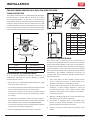
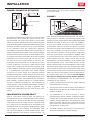
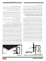
FLOOR PROTECTOR
This heater must have a non-combustible floor protector,
UL 1618 listed or equal, with an R-Value of at least
2.8 installed beneath it if the floor is constructed of
combustible material. The floor protector should be large
enough to extend under the stove and beyond each side
as indicated below. If there is a horizontal run of chimney
connector pipe, there needs to be floor protection under
it that extends two inches beyond either side of the pipe.
REAR
FRONT
SIDE SIDE
Front 18” (457 mm)
Sides 8” (204 mm)
Rear 2” (51 mm)
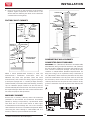
CLEARANCES TO COMBUSTIBLES
It is of utmost importance that the clearances to
combustible materials be strictly adhered to during
installation of the stove.
• Do not place any combustible material within 18” (458
mm) of the front of the unit.
• The clearance between the flue pipe and a wall are valid
only for vertical walls and for vertical flue pipe.
• The chimney connector must not pass through an attic
or roof space, closet or similar concealed space, a floor,
or a ceiling.
• For Canadian installations, where passage through a
wall, or partition of combustible construction is desired,
the installation must conform to CAN/CSA-B365.
• To reduce flue clearances from combustible materials,
contact your local safety department.
• Floor to ceiling height must be at least 7’ (2.13m).
E
F
E
D
B
AC
Key in mm
A 13 331
B 13 331
C14.5 369
D 18 458
E 10 254
F15.5 394
G 60 1524
H84 2134
G
H
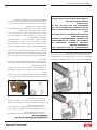
OUTSIDE COMBUSTION AIR
Your wood stove is approved to be installed with an
outside air intake (4FAK) which is necessary for a mobile
home/transportable building. This type of installation is
also required in air tight houses and houses with negative
pressure problems. You can purchase this option through
your heater dealer. Make sure to specify the part number
mentioned in this booklet. Installation instructions are
supplied with the air intake kit. Outside combustion air
may be required if:
1. Your stove does not draw steadily, smoke roll-out
occurs, wood burns poorly, or back-drafts occur
whether or not there is combustion present.
2. Existing fuel-fired equipment in the house, such as
fireplaces or other heating appliances, smell, do
not operate properly, suer smoke roll-out when
opened, or back-drafts occur whether or not there is
combustion present.
3. Opening a window slightly on a calm (windless) day
alleviates any of the above symptoms.
4. The house is equipped with a well-sealed vapor
barrier and tight fitting windows and/or has any
powered devices that exhaust house air.
5. There is excessive condensation on windows in the
winter.
FOR CUSTOMER SERVICE CALL: 8007502723 EXT 5050

8
© 2023 United States Stove Company
INSTALLATION
6. A ventilation system is installed in the house.
Slide the hose clamp over the aluminium flex pipe.
Then slide the flex pipe over the air intake tube of the
stove. Next tighten the hose clamp over the end of the
aluminium flex hose.
FOR USE IN MOBILE HOME/TRANSPORTABLE
BUILDINGS
• WARNING! DO NOT INSTALL IN SLEEPING
ROOM.
• CAUTION! THE STRUCTURAL INTEGRITY
OF THE MOBILE HOME/TRANSPORTABLE
BUILDING FLOOR, WALL, AND CEILING/ROOF
MUST BE MAINTAINED.
• INSTALL IN ACCORDANCE WITH 24 CFR, PART
3280 (HUD).
• USE A FACTORY BUILT CHIMNEY THAT
COMPLIES WITH UL 103 STANDARDS;
THEREFORE IT MUST BE A TYPE HT (2100°F).
• USE A SPARK ARRESTER.
• THE STOVE MUST BE ATTACHED TO THE
STRUCTURE OF THE MOBILE HOME/
TRANSPORTABLE BUILDING.
SECURING APPLIANCE’S WITH LEGS TO
THE FLOOR
1. The bracket engages around the square extrusion of
the leveling bolt inserted into the leg.
2. Once appliance is leveled, position the bracket and
attach to the floor using the appropriate hardware
needed for your specific flooring.
3. Install one bracket per leg or consult your local
authority having jurisdiction to determine how many
points of attachment are required.
In addition to the previously detailed installation
requirements, mobile home/transportable building
installations must meet the following requirements:
• The space heater is to be connected to a factory-built
chimney conforming to UL 103, Standard for 650°C
Factory-Built Chimneys.
• The heater must be permanently attached to the floor.
There are two holes in the pedestal base, use 3/8” bolts
through the floor.
• The heater must be electrically grounded to the steel
chassis of the mobile home/transportable building
with 8 GA copper wire using a serrated or star washer
to penetrate paint or protective coating to ensure
grounding.
• When moving your mobile home/transportable
building, all exterior venting must be removed while the
mobile home/transportable building is being relocated.
After relocation, all venting must be reinstalled and
securely fastened.
• Outside Air is mandatory for mobile home/transportable
building installation. See your dealer for purchasing.
• Check with your local building ocials as other codes
may apply.
• Only use the specified components listed in this manual
for this unit. The use of components that are not meant
for this unit can cause unsafe conditions.

© 2023 United States Stove Company
9
INSTALLATION
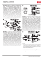
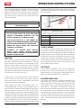
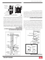
CHIMNEY CONNECTOR (STOVE PIPE)
3 screws
Flow
Direction
of Flue
Gases
Install
crimped
end
towards
stove.
Male Part Downwards
1/4” slope per foot
The chimney connector and chimney must have the same
diameter as the stove outlet (6”). If this is not the case,
we recommend you contact your dealer to ensure there
will be no problem with the draft. The stovepipe must be
made of aluminized or cold roll steel and have a minimum
thickness of 0.021” or 0.53 mm. It is strictly forbidden
to use galvanized steel. The smoke pipe should be
assembled to promote the male section (crimped end) of
the pipe to be faced down. Attach each section to another
with three metal screws spaced an equal distance apart.
The pipe must be short and straight. All sections installed
horizontally must slope at least 1/4 inch per foot, with
the upper end of the section toward the chimney. Any
installation with a horizontal run of chimney pipe must
conform to NFPA 211. To ensure a good draft, the total
length of the coupling pipe should never exceed 8’ to 10’
(2.4m to 3.04m). Except for cases of vertical installation,
in a cathedral-roof style where the smoke exhaust
system can be much longer and connected without
problem to the chimney at the ceiling of the room. There
should never be more than two 90 degrees elbows in the
smoke exhaust system. The installation of a “barometric
draft stabilizer” (fireplace register) on a smoke exhaust
system is prohibited. Furthermore, the installation of
a draft damper is not recommended. With a controlled
combustion wood stove, the draft is regulated upon
intake of the combustion air in the stove and not at the
exhaust.
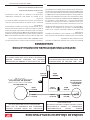
IMPORTANCE OF PROPER DRAFT
Draft is a force that moves air from the appliance up
through the chimney. The amount of draft in your chimney
depends on the length of the chimney, local geography,
nearby obstructions and other factors. Too much draft
may cause excessive temperatures in the appliance. An
inadequate draft may cause back-pung into the room
and “plugging” of the chimney. An inadequate draft
will cause the appliance to leak smoke into the room
through appliance and chimney connector joints. An
uncontrollable burn or excessive temperature indicates
an excessive draft.
CHIMNEY
Your wood stove may be hooked up with a 6” factory-
built or masonry chimney. If you are using a factory-built
chimney, it must comply with UL 103 or CAN/ULC-S629
standard; therefore it must be a Type HT (2100°F).
It must be installed according to the manufacturer’s
specifications. Take into account the chimney’s location
to ensure it is not too close to neighbors or in a valley which
may cause unhealthy or nuisance conditions. If you are
using a masonry chimney, it must be built in compliance
with the specifications of the National Building Code.
It must be lined with fire clay bricks, metal or clay tiles
sealed together with fire cement. Round flues are the
most ecient. The interior diameter of the chimney flue
must be identical to the stove smoke exhaust. A flue
which is too small may cause draft problems, while a large
flue favors rapid cooling of the gas, and hence the build-
up of creosote and the risk of chimney fires. Note that it
is the chimney and not the stove which creates the draft
eect; your stove’s performance is directly dependent on
an adequate draft from your chimney. Do not connect
this unit to a chimney flue serving another appliance.
The following recommendations may be useful for the
installation of your chimney:
1. It must rise above the roof at least 3’ (0.9m) from the
uppermost point of contact.
2. The chimney must exceed any part of the building or
other obstruction within a 10’ (3.04m) distance by a
height of 2’ (0.6m).
3. The installation of an interior chimney is always
preferable to an exterior chimney. Indeed, the interior
chimney will, by definition, be hotter than an exterior
chimney, being heated up by the ambient air in the
house. Therefore the gas which circulates will cool
more slowly, thus reducing the build-up of creosote
and the risk of chimney fires.
4. The draft caused by the tendency for hot air to rise
will be increased with an interior chimney.

10
© 2023 United States Stove Company
INSTALLATION
5. Using a fire screen at the extremity of the chimney
requires regular inspection to ensure that it is not
obstructed thus blocking the draft, and it should be
cleaned when used regularly.
FACTORY BUILT CHIMNEY
Listed Cap
Maintain 2”
Clearance
Listed
Chimney
Ceiling
Support
Ceiling
Support
Chimney
Connector
** Refer to Clearance
to Combustibles
Combustible Wall
Floor
Protector
To Stove
Storm Collar
Flashing
Listed
Chimney Attic
Insulation
Sheild
Specified
Clearance
Chimney
Connector
Combustible
Ceiling Joists
To Stove
When a metal prefabricated chimney is used, the
manufacturer’s installation instructions must be
followed. You must also purchase (from the same
manufacturer) and install the ceiling support package
or wall pass-through and “T” section package, firestops
(where needed), insulation shield, roof flashing, chimney
cap, etc. Maintain proper clearance to the structure as
recommended by the manufacturer. The chimney must be
the required height above the roof or other obstructions
for safety and proper draft operation.
MASONRY CHIMNEY
Ensure that a masonry chimney meets the minimum
standards of the National Fire Protection Association
(NFPA) by having it inspected by a professional. Make
sure there are no cracks, loose mortar or other signs
of deterioration and blockage. Be sure to the chimney
cleaned before the stove is installed and operated. When
connecting the stove through a combustible wall to a
masonry chimney, special methods are needed.
Sheathing
Airtight
Cleanout
Door
Floor
Protector
Thimble
12” of Brick
Combustible Wall
1” Clearance
with Firestop
Rafter
Concrete Cap
Flashing
To Stove
1” Clearance
Eave
Flashing
Fireclay Flue
Liner With
Airspace
COMBUSTIBLE WALL CHIMNEY
CONNECTOR PASSTHROUGHS
METHOD A - 12” (304.8 mm) Clearance to Combustible
Wall Member: Using a minimum thickness 3.5” (89 mm)
brick and a 5/8” (15.9 mm) minimum wall thickness clay
liner, construct a wall pass-through. The clay liner must
conform to ASTM C315 (Standard Specification for
Clay Fire Linings) or its equivalent. Keep a minimum of
12” (304.8 mm) of brick masonry between the clay liner
and wall combustibles. The clay liner shall run from the
brick masonry outer surface to the inner surface of the
chimney flue liner but not past the inner surface. Firmly
grout or cement the clay liner in place to the chimney flue
liner.

© 2023 United States Stove Company
11
INSTALLATION
METHOD B - 9” (228.6 mm) Clearance to Combustible
Wall Member: Using a 6” (152.4 mm) inside diameter,
listed, factory-built Solid-Pak chimney section with
insulation of 1” (25.4 mm) or more, build a wall pass-
through with a minimum 9” (228.6 mm) air space
between the outer wall of the chimney length and wall
combustibles. Use sheet metal supports fastened
securely to wall surfaces on all sides, to maintain the
9” (228.6 mm) air space. When fastening supports to
chimney length, do not penetrate the chimney liner (the
inside wall of the Solid-Pak chimney). The inner end of
the Solid-Pak chimney section shall be flush with the
inside of the masonry chimney flue, and sealed with a
non-water soluble refractory cement. Use this cement to
also seal to the brick masonry penetration.
METHOD C - 6” (152.4 mm) Clearance to Combustible
Wall Member: Starting with a minimum 24 gage (.024”
[.61 mm]) 6” (152.4 mm) metal chimney connector, and
a minimum 24 gage ventilated wall thimble which has
two air channels of 1” (25.4 mm) each, construct a wall
pass-through. There shall be a minimum 6” (152.4 mm)
separation area containing fiberglass insulation, from the
outer surface of the wall thimble to wall combustibles.
Support the wall thimble, and cover its opening with a
24-gage minimum sheet metal support. Maintain the 6”
(152.4 mm) space. There should also be a support sized
to fit and hold the metal chimney connector. See that
the supports are fastened securely to wall surfaces on
all sides. Make sure fasteners used to secure the metal
chimney connector do not penetrate chimney flue liner.
METHOD D - 2” (50.8 mm) Clearance to Combustible
Wall Member: Start with a solid-pak listed factory
built chimney section at least 12” (304 mm) long, with
insulation of 1” (25.4 mm) or more, and an inside diameter
of 8” (2 inches [51 mm] larger than the 6” [152.4 mm]
chimney connector). Use this as a pass-through for a
minimum 24-gauge single wall steel chimney connector.
Keep solid-pak section concentric with and spaced 1”
(25.4 mm) o the chimney connector by way of sheet
metal support plates at both ends of chimney section.
Cover opening with and support chimney section on both
sides with 24 gage minimum sheet metal supports. See
that the supports are fastened securely to wall surfaces
on all sides. Make sure fasteners used to secure chimney
flue line do not penetrate the inner liner.
NOTES:
• Connectors to a masonry chimney, excepting method
B, shall extend in one continuous section through the
wall pass-through system and the chimney wall, to but
not past the inner flue liner face.
• A chimney connector shall not pass through an attic or
roof space, closet or similar concealed space, or a floor,
or ceiling.

12
© 2023 United States Stove Company
OPERATION INSTRUCTIONS
CAUTIONS: HOUSE FIRE HAZARDS
• DO NOT STORE WOOD ON FLOOR PROTECTOR,
UNDERNEATH STOVEPIPE(S) OR ANYWHERE
WITHIN CLEARANCES TO COMBUSTIBLE
SURFACES SPECIFIED FOR THIS APPLIANCE.
• NEVER OPERATE WITH SECONDARY TUBES,
FIBERBOARD, OR INSULATION REMOVED.
OPERATING SAFETY PRECAUTIONS
• NEVER OVERFIRE THIS APPLIANCE BY
BUILDING EXCESSIVELY HOT FIRES AS A
HOUSE/BUILDING FIRE MAY RESULT. YOU ARE
OVERFIRING THE APPLIANCE IF IT BEGINS TO
GLOW OR TURN RED.
• NEVER BUILD EXCESSIVELY LARGE FIRES IN
THIS TYPE OF APPLIANCE AS DAMAGE TO THE
FIREBOX OR SMOKE LEAKAGE MAY RESULT.
• DO NOT BUILD FIRE TOO CLOSE TO THE GLASS.
• HOT WHILE IN OPERATION. KEEP CHILDREN,
CLOTHING, AND FURNITURE AWAY. CONTACT
MAY CAUSE SKIN BURNS. DO NOT TOUCH THE
APPLIANCE UNTIL IT HAS COOLED.
• PROVIDE ADEQUATE AIR FOR COMBUSTION
TO THE ROOM WHERE THE APPLIANCE IS
INSTALLED.
• INSPECT CHIMNEY LINER EVERY 60 DAYS.
REPLACE LINER IMMEDIATELY IF IT IS RUSTING
OR LEAKING SMOKE INTO THE ROOM.
• ATTEMPTS TO ACHIEVE HEAT OUTPUT
RATES THAT EXCEED HEATER DESIGN
SPECIFICATIONS CAN RESULT IN PERMANENT
DAMAGE TO THE HEATER.
WARNING: EXPLOSION HAZARD
• NEVER USE CHEMICALS, GASOLINE, GASOLINE-
TYPE LANTERN FUEL, KEROSENE, CHARCOAL
LIGHTER FLUID, OR SIMILAR FLAMMABLE
LIQUIDS TO START OR “FRESHEN UP” A FIRE IN
THE APPLIANCE.
• KEEP ALL FLAMMABLE LIQUIDS, ESPECIALLY
GASOLINE, OUT OF THE VICINITY OF THE
APPLIANCE - WHETHER IN USE OR IN STORAGE.
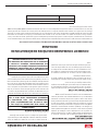
WOOD STOVE UTILIZATION
Your heating appliance was designed to burn well
seasoned natural wood only; no other materials should
be burned. Any type of well seasoned natural wood
may be used in your stove, but specific varieties have
better energy yields than others. Higher eciencies and
lower emissions generally result when burning air dried
seasoned hardwoods, as compared to softwoods or too
green or freshly cut hardwoods. The following resources
can assist in learning the burn characteristics of various
species of wood:
http://firewoodresource.com/firewood-btu-ratings/; or
https://forestry.usu.edu/forest-products/wood-heating
The operation of this wood heater in a manner
inconsistent with the owner’s manual will void your
warranty and is also against federal regulations. Waste
and other flammable materials should not be burned in
your stove. DO NOT BURN:
1. Garbage;
2. Lawn clippings or yard waste;
3. Materials containing rubber, including tires;
4. Materials containing plastic;
5. Waste petroleum products, paints or paint thinners,
or asphalt products;
6. Materials containing asbestos;
7. Construction or demolition debris;
8. Railroad ties or pressure-treated wood;
9. Manure or animal remains;
10. Saltwater driftwood or other previously salt water-
saturated materials;
11. Unseasoned wood; or
12. Paper products, cardboard, plywood, or particleboard.
The prohibition against burning these materials does
not prohibit the use of fire starters made from paper,
cardboard, sawdust, wax, and similar substances to
start a fire in an aected wood heater.
Burning these materials may result in the release of toxic
fumes or render the heater ineective and cause smoke.
Deadwood lying on the forest floor should be considered
wet and requires full seasoning time. Standing deadwood
can usually be considered to be about 2/3 seasoned.
Smaller pieces of wood will dry faster. All logs exceeding
6” in diameter should be split. The wood should not be
stored directly on the ground. Air should circulate through
NEVER OPERATE THIS PRODUCT WHILE UNATTENDED

© 2023 United States Stove Company
13
OPERATION INSTRUCTIONS
the logs. A 24” to 48” air space should be left between
each row of logs, which should be placed in the sunniest
location possible. The upper layer of wood should be
protected from the element but not the sides. A good
indicator of if the wood is ready to burn is to check the
piece ends. If cracks are radiating in all directions from
the center then the wood should be dry enough to burn.
If your wood sizzles in the fire, even though the surface
is dry, it may not be fully cured and should be seasoned
longer. It is EXTREMELY IMPORTANT that you use DRY
WOOD only in your wood stove. The wood should have
dried for 9 to 15 months, such that the humidity content
(in weight) is reduced below 20% of the weight of the log.
It is very important to keep in mind that even if the wood
has been cut for one, two, or even more years, it is not
necessarily dry, if it has been stored in poor conditions.
Under extreme conditions, it may rot instead of drying.
This point cannot be overstressed; the vast majority of
the problems related to the operation of a wood stove is
caused by the fact that the wood used was too damp or
had dried in poor conditions. These problems can be:
• ignition problems
• creosote build-up causing chimney fires
• low energy yield
• blackened windows
• incomplete log combustion
Do not burn manufactured logs made of wax
impregnated sawdust or logs with any chemical
additives.
TESTING YOUR WOOD
• When the stove is thoroughly warmed, place one piece
of split wood (about five inches in diameter) parallel to
the door on the bed of red embers.
• Keep the air control fully open and close the door. If
the wood ignites within 90 seconds from the time it
was placed in the stove, your wood is correctly dried. If
ignition takes longer, your wood is damp.
• If your wood hisses and water or vapor escapes at
the ends of the piece, your wood is soaked or freshly
cut (green). Do not use this wood in your stove. Large
amounts of creosote could be deposited in your
chimney, creating potential conditions for a chimney
fire.
TAMPER WARNING
This wood heater has a manufacturer-set minimum low
burn rate that must not be altered. It is against federal
regulations to alter this setting or otherwise operate this
wood heater in a manner inconsistent with operating
instructions in this manual.
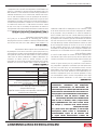
EFFICIENCIES
Eciencies can be based on either the lower heating
value (LHV) or the higher heating value (HHV) of the
fuel. The lower heating value is when water leaves the
combustion process as a vapor, in the case of woodstoves
the moisture in the wood being burned leaves the stove
as a vapor. The higher heating value is when water leaves
the combustion process completely condensed. In the
case of woodstoves this would assume the exhaust gases
are room temperature when leaving the system, and
therefore calculations using this heating value consider
the heat going up the chimney as lost energy. Therefore,
eciency calculated using the lower heating value of
wood will be higher than eciency calculated using the
higher heating value. The best way to achieve optimum
eciencies is to learn the burn characteristic of you
appliance and burn well-seasoned wood. Higher burn
rates are not always the best heating burn rates; after a
good fire is established a lower burn rate may be a better
option for ecient heating. A lower burn rate slows the
flow of usable heat out of the home through the chimney,
and it also consumes less wood.
NOTICE INITIAL BURNS TO CURE PAINT
BECAUSE OF THE HIGH OPERATING TEMPERATURES,
THIS APPLIANCE IS COATED WITH A SPECIAL HIGH
TEMP PAINT WHICH REQUIRES A SERIES OF LOW TO
MEDIUM BURNS TO FULLY CURE FOR DURABILITY
AND A LIFETIME OF SERVICE.
Proper curing of the high-temp paint requires a series of
three initial burns. The appliance should be allowed to
cool o between each burn. The first two burns should
be small fires and low temperatures (250°F) for a
duration of 20 minutes each. The third fire should be at
a temperature of approximately 500°F for 20 minutes.
Provide adequate cross ventilation to clear any smoke or
odor caused by initial firings.
Notice: Use solid wood fuel only! Do not burn garbage,
or flammable fluids. Do not use coal. This appliance
is not designed to accommodate the air flow (draft)
required to properly burn coal or coal products. Do
not elevate the fire using grates or irons. Build the fire
directly on the firebrick.
FUELING INSTRUCTIONS
This wood stove has been certified by the US EPA
to meet strict 2020 guidelines. To ensure this unit
produces the optimal minimum emissions it is critical

14
© 2023 United States Stove Company
OPERATION INSTRUCTIONS
that only well-seasoned cordwood is burned (see the
“Fuel Recommendations” section of this manual).
Burning unseasoned wet wood only hurts your stoves
eciency and leads to accelerated creosote buildup in
your chimney. Be considerate of the environment and
only burn dry wood.
CAUTION:
DO NOT LEAVE APPLIANCE UNATTENDED THE
WITH DOOR OPEN.
WARNINGS:
• NEVER OVERFIRE YOUR STOVE. IF ANY PART
OF THE STOVE STARTS TO GLOW RED, OVER
FIRING IS HAPPENING. READJUST THE AIR
INTAKE CONTROL AT A LOWER SETTING.
• THE INSTALLATION OF A LOG CRADLE OR
GRATES IS NOT RECOMMENDED IN YOUR WOOD
STOVE. BUILD FIRE DIRECTLY ON FIREBRICK.
• NEVER PUT WOOD ABOVE THE FIREBRICK
LINING OF THE FIREBOX.
• ATTEMPTS TO ACHIEVE HEAT OUTPUT
RATES THAT EXCEED HEATER DESIGN
SPECIFICATIONS CAN RESULT IN PERMANENT
DAMAGE TO THE HEATER.
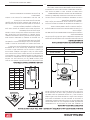
IGNITION
After making sure that the stove air intake controls are
fully open (completely pull-out towards you), The top
down method of fire building is recommended for this
appliance. After making sure that the stove air intake
controls are fully open (completely pull-out towards
you), Place the largest pieces of wood on the bottom, laid
in parallel and close together. Smaller pieces are placed in
a second layer, crossways to the first.
A third layer of still smaller pieces is laid crossways
to the second, this time with some spaces between.
Then a fourth layer of loose, small kindling and twisted
newspaper sheets tops o the pile.
Before igniting the paper and kindling wood, it is
recommended that you warm up the chimney. This is
done in order to avoid back draft problems often due to
negative pressure in the house. If such is the case, open
a window slightly near the stove and twist together a few
sheets of newspaper into a torch. Light up this paper torch
and hold it as close as possible to the mouth of the pipe
inside the combustion chamber to warm up the chimney.
Once the updraft movement is initiated, you are ready to
ignite the stove by lighting the paper and kindling wood
inside the combustion chamber. When you have achieved
a good bed of hot embers, we recommend the following
burn procedures:
HIGH
LOW
Primary Air Settings
(Slide Damper is located in center of stove under hearth plate)
(Damper Adjustment: Pulling out on damper increases air)
Burn Rate Adjust Damper From Fully Closed
Low Closed
Medium 1/8” (3.18mm)
Medium - High 1/2” (12.7mm)
High Pull Rod Out Fully
VISIBLE SMOKE
The amount of visible smoke being produced can be
an eective method of determining how eciently the
combustion process is taking place in the given settings.
Visible smoke consists of unburned fuel and moisture
leaving your stove. Learn to adjust the air settings of your
specific unit to produce the smallest amount of visible
smoke. Wood that has not been seasoned properly and
has a high wood moisture content will produce excess
visible smoke and burn poorly.
AIR TUBES
The air tubes assembled in this unit are designed to
provide an accurate mix of secondary air to ensure the
highest eciency. Any damage or deterioration of these
tubes may reduce the eciency of combustion.
BLOWER OPERATION
The variable-speed blower circulates air warmed by the
firebox into the living area to distribute the heat more
evenly. The blower control knob is located on the side
of the blower housing. Turn the knob clockwise to turn
the blower on. The speed is controlled by turning the
knob clockwise for slower speeds and counter-clockwise
for faster speeds. To turn the blower o, turn the speed
control knob fully counter-clockwise. It is recommended
to turn the blower o when the unit is not in operation.
The blower should be removed at the beginning of every
“burn” season and air-blown clean, removing any dust or
build-up.

© 2023 United States Stove Company
15
CHIMNEY MAINTENANCE
CAUTION:
DO NOT OVERFIRE APPLIANCE. YOU ARE
OVERFIRING IF ANY PART OF THE APPLIANCE
GLOWS RED. CLOSE THE DOOR AND SHUT DAMPER
IMMEDIATELY TO REDUCE THE AIR SUPPLY AND
SLOW DOWN THE FIRE.
CAUTION:
SLOW BURNING FIRES FOR EXTENDED USE OR
BURNING GREEN WOOD MAY CAUSE EXCESSIVE
CREOSOTE BUILD-UP. IGNITION OF CREOSOTE
OR OVERFIRING COULD CAUSE A CHIMNEY
FIRE. CHIMNEY FIRES BURN EXTREMELY HOT
AND MAY IGNITE SURROUNDING COMBUSTIBLE
MATERIALS. IN CASE OF A CHIMNEY FIRE, CALL
THE FIRE DEPARTMENT IMMEDIATELY!
CREOSOTE FORMATION AND NEED FOR
REMOVAL
When wood is burned slowly, it produces tar and other
organic vapors, which combine with expelled moisture
to form creosote. The creosote vapors condense in the
relatively cool chimney flue of a slow-burning fire. As a
result, creosote residue accumulates on the flue lining.
When ignited this creosote makes an extremely high
temper fire. The chimney connector and chimney should
be inspected at least once every two months during the
heating season to determine if a creosote build-up has
occurred. If creosote has accumulated (3 mm or more),
it should be removed to reduce the risk of a chimney fire.
We strongly recommend that you install a magnetic
thermometer on your smoke exhaust pipe, approximately
18” above the stove. This thermometer will indicate the
temperature of your gas exhaust fumes within the smoke
exhaust system. The ideal temperature for these gases
is somewhere between 275°F and 500°F. Below these
temperatures, the build-up of creosote is promoted.
Above 500°F, heat is wasted since a too large quantity is
lost into the atmosphere.
TO PREVENT CREOSOTE BUILD UP
• Always burn dry wood. This allows clean burns and
higher chimney temperatures, therefore less creosote
deposit.
• Leave the air control fully open for about 5 min. every
time you reload the stove to bring it back to proper
operating temperatures. The secondary combustion
can only take place if the firebox is hot enough.
• Always check for creosote deposit once every two
months and have your chimney cleaned at least once
a year.
• If a chimney or creosote fire occurs, close all dampers
immediately. Wait for the fire to go out and the heater
to cool, then inspect the chimney for damage. If no
damage results, perform a chimney cleaning to ensure
no more creosote deposits is remaining in the chimney.
CAUTION:
A CHIMNEY FIRE MAY CAUSE IGNITION OF WALL
STUDS OR RAFTERS WHICH WERE ASSUMED TO
BE A SAFE DISTANCE AWAY FROM THE CHIMNEY.
IF A CHIMNEY FIRE OCCURS, HAVE YOUR
CHIMNEY INSPECTED BY A QUALIFIED EXPERT
BEFORE USING AGAIN.
ASH REMOVAL & DISPOSAL
Whenever ashes get 3 to 4 inches deep in your firebox,
and when the fire has burned down and cooled, remove
excess ashes. Leave an ash bed approximately 1 inch deep
on the firebox bottom to help maintain a hot charcoal bed.
Ashes should be placed in a metal container with a tight-
fitting lid. The closed container of ashes should be placed
on a non-combustible floor or the ground, away from all
combustible materials, pending final disposal. The ashes
should be retained in the closed container until all cinders
have thoroughly cooled.
CAUTIONS:
• ASHES COULD CONTAIN HOT EMBERS EVEN
AFTER TWO DAYS WITHOUT OPERATING THE
STOVE.
• THE ASH PAN CAN BECOME VERY HOT. WEAR
GLOVES TO PREVENT INJURY.
• NEVER BURN THE STOVE WITH THE ASH TRAP
OPEN. THIS WOULD RESULT IN OVER FIRING
THE STOVE. DAMAGE TO THE STOVE AND EVEN
HOUSE FIRE MAY RESULT.
SMOKE & CO MONITORS
Burning wood naturally produces smoke and carbon
monoxide(CO) emissions. CO is a poisonous gas when
exposed to elevated concentrations for extended
periods. While the modern combustion systems in
heaters drastically reduce the amount of CO emitted
NEVER OPERATE THIS PRODUCT WHILE UNATTENDED

16
© 2023 United States Stove Company
CHIMNEY MAINTENANCE
out the chimney, exposure to the gases in closed or
confined areas can be dangerous. Make sure your stove
gaskets and chimney joints are in good working order
and sealing properly to ensure unintended exposure. It is
recommended that you use both smoke and CO monitors
in areas having the potential to generate CO.
GLASS CARE
• Inspect and clean the glass regularly to detect any
cracks. If you spot one, turn the stove o immediately.
Do not abuse the glass door by striking or slamming
shut. Do not use the stove if the glass is broken.
• If the glass on your stove breaks, replace only with
the glass supplied from your heater dealer. Never
substitute other materials for the glass.
• To replace the glass, remove the screws retaining the
glass moldings inside the door. Remove the moldings
and replace the damaged piece with a new one.
Perform the procedure backward after replacing it.
When replacing the glass, you should change the glass
gasket to make sure you keep it sealed.
• Never wash the glass with a product that may scratch.
Use a specialized product, available in the stores where
wood stoves are sold. The glass should be washed only
when cold.
GASKET CARE
WARNING:
NEVER OPERATE THE STOVE WITHOUT THE
GASKET OR WITH A DAMAGED OR BROKEN
GASKET. OPERATING WITHOUT A GASKET OR
DAMAGED GASKET WILL RESULT IN DAMAGE TO
YOUR STOVE AND CAN RESULT IN A HOUSE FIRE.
This unit’s door uses a 5/8” diameter rope gasket. It is
recommended that you change the door gasket (which
makes your stove door air tight) once a year, in order
to ensure good control over the combustion, maximum
eciency and security. To change the door gasket, simply
remove the damaged one. Carefully clean the available
gasket groove, apply a high temperature silicone sold for
this purpose, and install the new gasket. You may light
up your stove again approximately 24 hours after having
completed this operation.
ATTENTION:
THIS WOOD HEATER NEEDS PERIODIC INSPECTION
AND REPAIR FOR PROPER OPERATION. IT IS
AGAINST FEDERAL REGULATIONS TO OPERATE
THIS WOOD HEATER IN A MANNER INCONSISTENT
WITH OPERATING INSTRUCTIONS IN THIS
MANUAL.
For Parts Assistance Call: 800-750-2723 Ext 5051 or Email: parts@usstove.com
The information in this owner’s manual is specific to your unit. When ordering replacement parts the information
in this manual will help to ensure the correct items are ordered. Before contacting customer service write down the
model number and the serial number of this unit. That information can be found on the certification label attached
to the back of the unit. Other information that may be needed would be the part number and part description of the
item(s) in question. Part numbers and descriptions can be found in the “Repair Parts” section of this manual. Once
this information has been gathered you can contact customer service by phone 1-800-750-2723 Ext 5051 or Email
parts@usstove.com.
Model Information
Model Number
Serial Number
HOW TO ORDER REPAIR PARTS

© 2023 United States Stove Company
17
INSTRUCTIONS SPECIFIC FOR CANADIAN
INSTALLATIONS
Do not obstruct the space under the heater and do not
obstruct the combustion air openings.
Refer to the chimney manufacturer’s instructions for
disassembling the chimney for transportation of a
transportable building.
This heater meets the requirements of CAN/ULC-S627
and is suitable for installation on a combustible floor and
does not require radiant floor protection.
The parts or materials to be employed for ember
protectors and the minimum areas to be covered and
their relation to the space heater, as well as the notice:
“In Canada, to comply with CSA B365, Installation Code
for Solid-Fuel-Burning Appliances and Equipment, any
combustible covering beneath the appliance and/or
within the area extending horizontally at least 450 mm
(18 in) beyond the appliance on any side equipped with a
door, and at least 200 mm (8 in) beyond the appliance on
other sides, shall be protected by a continuous, durable,
non-combustible pad that will provide ember protection.
The 450 mm (18 in) ember protection required on any
side with a
door shall extend for the full width of the appliance plus
the 200 mm (8 in) required on each side of the appliance
without a door. Where an appliance is installed less than
200 mm (8 in) from a wall, the ember pad need only
extend to the base of the wall. An ember pad shall not be
placed on top of a carpet unless the pad is structurally
supported to prevent displacement and distortion.
Note: Do not install the chimney directly at the outlet
of the appliance. A chimney connector (flue pipe) is
required.
If this appliance is installed in a transportable building,
removal of the chimney is required for transportation of
the building.
DO NOT INSTALL IN AN ALCOVE
DO NOT INSTALL IN ANY FIREPLACE
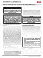
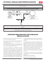
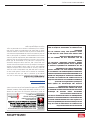
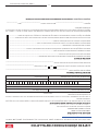
OPTIONAL CB36 BLOWER WIRING DIAGRAM
WHITE /
BLANC
GREEN /
VERT
WHITE /
BLANC
BLACK /
NOIR
BLACK /
NOIR
BLACK /
NOIR
BLOWER
RHEOSTAT /
RHÉOSTAT DU
VENTILATEUR
BLOWER MOTOR
BLOWER SPECS: 120VAC, 60 Hz AC,0.55amp /
MTEUR DU
VENTILATEUR
DÉTAILS TECHNIQUES: 120VAC, 60 Hz CA,0,55AMP
BLACK /
NOIR
BLACK /
NOIR
NOTICE: DO NOT ALLOW THE POWER CORD TO TOUCH HOT SURFACES! KEEP THE POWER CORD AT LEAST
12”/30.5CM FROM THE STOVE OR PIPE SURFACES.
DANGER: SHOCK HAZARD DISCONNECT POWER SOURCE BEFORE INSTALLATION AND WHENEVER SERVICING
BLOWER ASSEMBLY.
CAUTION: MOVING PARTS CAN CAUSE INJURY. DO NOT OPERATE WITH COVER REMOVED.
NOTICE: ANY REPLACEMENT WIRING MUST HAVE EQUIVALENT INSULATION AND TEMPERATURE RATING
(105° C).

18
© 2023 United States Stove Company
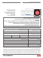
IN ORDER TO MAINTAIN WARRANTY, COMPONENTS MUST BE REPLACED USING ORIGINAL
MANUFACTURERS PARTS PURCHASED THROUGH YOUR DEALER OR DIRECTLY FROM THE APPLIANCE
MANUFACTURER. USE OF THIRD PARTY COMPONENTS WILL VOID THE WARRANTY.
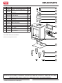
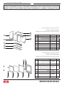
REPAIR PARTS
Key Part # Description Qty
183432 5/16-18 X 1-1/2 HX HD C/S PL 3
283045 Washer, 5/16”ID X 3/4” OD X
1/16 THK 3
3 893719 Diuser 1
440292A 6” Flue Collar 1
588042 1/4” Rope Gasket 1
683431 Weld Tab 3
7 50BK Blower Kit 1
8 CB36 Blower Assembly 1
9 893162 Knob, Wooden 1
10 50FAK Fresh Air Kit 1
11 40754 Leg, 8KW 4
12 83525 Elevator Bolt 4
13 29104 Leg Fastener 2
1
2
3
4
5
6
9
10
11
12
13
7
8
To order parts:
Call 1-800-750-2723 Ext 5051 or
Email to: parts@usstove.com

© 2023 United States Stove Company
19
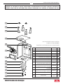
IN ORDER TO MAINTAIN WARRANTY, COMPONENTS MUST BE REPLACED USING ORIGINAL
MANUFACTURERS PARTS PURCHASED THROUGH YOUR DEALER OR DIRECTLY FROM THE APPLIANCE
MANUFACTURER. USE OF THIRD PARTY COMPONENTS WILL VOID THE WARRANTY.
REPAIR PARTS
To order parts:
Call 1-800-750-2723 Ext 5051 or
Email to: parts@usstove.com
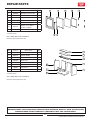
Key Part # Description Qty
1 893910 Wooden Scale Handle 1
2893730 Handle 1
3 40909 Door 1
4 88126 5/8” Rope Gasket 1
5 893718 Main Glass 1
6 88174 Gasket - Flat, Glass
(3/16T x 3/8W) 1
7 893731 Glass Clamp 4
3
2 1
4 5 6 7
To order parts:
Call 1-800-750-2723 Ext 5051 or
Email to: parts@usstove.com
Key Part # Description Qty
1 893716 Top Bae 1
2 893711 Bottom Bae 1
3 893717 Tube Assembly 1
4 893713 Back Liner 2
5 893715 Right Liner 1
6 893712 Left Liner 1
7 40911 Log Guard 1
8 893714 Bottom Liner 1 5
6
8
7
4
3
2
1

20
© 2023 United States Stove Company
SERVICE RECORD
It is recommended that your heating system is serviced regularly and that the appropriate Service Interval Record is
completed.
SERVICE PROVIDER
Before completing the appropriate Service Record below, please ensure you have carried out the service as described in
the manufacturer’s instructions. Always use the manufacturer's specified spare part when replacement is necessary.
Service 01 Date: ______________________
Engineer Name: ____________________________________
License No.: ________________________________________
Company: __________________________________________
Telephone No.: _____________________________________
Stove Inspected: Chimney Swept:
Items Replaced: ____________________________________
Service 03 Date: ______________________
Engineer Name: ____________________________________
License No.: ________________________________________
Company: __________________________________________
Telephone No.: _____________________________________
Stove Inspected: Chimney Swept:
Items Replaced: ____________________________________
Service 05 Date: ______________________
Engineer Name: ____________________________________
License No.: ________________________________________
Company: __________________________________________
Telephone No.: _____________________________________
Stove Inspected: Chimney Swept:
Items Replaced: ____________________________________
Service 07 Date: ______________________
Engineer Name: ____________________________________
License No.: ________________________________________
Company: __________________________________________
Telephone No.: _____________________________________
Stove Inspected: Chimney Swept:
Items Replaced: ____________________________________
Service 02 Date: ______________________
Engineer Name: ____________________________________
License No.: ________________________________________
Company: __________________________________________
Telephone No.: _____________________________________
Stove Inspected: Chimney Swept:
Items Replaced: ____________________________________
Service 04 Date: ______________________
Engineer Name: ____________________________________
License No.: ________________________________________
Company: __________________________________________
Telephone No.: _____________________________________
Stove Inspected: Chimney Swept:
Items Replaced: ____________________________________
Service 06 Date: ______________________
Engineer Name: ____________________________________
License No.: ________________________________________
Company: __________________________________________
Telephone No.: _____________________________________
Stove Inspected: Chimney Swept:
Items Replaced: ____________________________________
Service 08 Date: ______________________
Engineer Name: ____________________________________
License No.: ________________________________________
Company: __________________________________________
Telephone No.: _____________________________________
Stove Inspected: Chimney Swept:
Items Replaced: ____________________________________
La page est en cours de chargement...
La page est en cours de chargement...
La page est en cours de chargement...
La page est en cours de chargement...
La page est en cours de chargement...
La page est en cours de chargement...
La page est en cours de chargement...
La page est en cours de chargement...
La page est en cours de chargement...
La page est en cours de chargement...
La page est en cours de chargement...
La page est en cours de chargement...
La page est en cours de chargement...
La page est en cours de chargement...
La page est en cours de chargement...
La page est en cours de chargement...
La page est en cours de chargement...
La page est en cours de chargement...
La page est en cours de chargement...
La page est en cours de chargement...
-
 1
1
-
 2
2
-
 3
3
-
 4
4
-
 5
5
-
 6
6
-
 7
7
-
 8
8
-
 9
9
-
 10
10
-
 11
11
-
 12
12
-
 13
13
-
 14
14
-
 15
15
-
 16
16
-
 17
17
-
 18
18
-
 19
19
-
 20
20
-
 21
21
-
 22
22
-
 23
23
-
 24
24
-
 25
25
-
 26
26
-
 27
27
-
 28
28
-
 29
29
-
 30
30
-
 31
31
-
 32
32
-
 33
33
-
 34
34
-
 35
35
-
 36
36
-
 37
37
-
 38
38
-
 39
39
-
 40
40


United States Stove Company TH-100 Le manuel du propriétaire
- Catégorie
- Poêle à bois
- Taper
- Le manuel du propriétaire
dans d''autres langues
Documents connexes
-
United States Stove VG900 Le manuel du propriétaire
-
United States Stove VG180L Le manuel du propriétaire
-
-
-
United States Stove Company VG1120 Series Le manuel du propriétaire
-
Ashley Hearth Products AW2020E Manuel utilisateur
-
US Stove Company US2000E Series Le manuel du propriétaire