
Requirements
Source Device
The following equipment must be installed on the source device or
computer that acts as a source of VGA/Audio content:
• VGA video card with HDB-15 connector
• Audio source with stereo output
Display Device
• A VGA, SVGA, UXGA, WUXGA or multisync monitor or multimedia
projector with an HDB-15 connector
• Stereo audio speakers
Cables
• 1 VGA/Audio cable for each source device you will be connecting
• 1 VGA/Audio cable for your display device
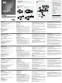
Hardware Review
A
VS0201/VS0401 Front View
1. Port Selection Pushbuttons
2. Port LEDs
3. Power Pushbutton
4. Power LED
Configuration minimale
Périphérique source
L’équipement suivant doit être installé sur le périphérique source ou sur
l’ordinateur servant de source du contenu VGA/audio :
• Carte vidéo VGA avec connecteur HDB-15
• Source audio avec sortie stéréo
Périphérique d’affichage
• Un moniteur VGA, SVGA, UXGA, WUXGA ou multisync ou un
projecteur multimédia équipé d'un connecteur HDB-15
• Haut-parleurs audio stéréo
Câbles
• 1 câble VGA/audio pour chaque périphérique source à installer
• 1 câble VGA/audio pour votre périphérique d’affichage
Description de l’appareil
A
VS0201/VS0401 Vue avant
1. Boutons de sélection de port
2. Voyants des ports
3. Bouton d’alimentation
4. Voyant d’alimentation
Voraussetzungen
Signalquelle
Auf den Signalquellen oder Computern, die das VGA-/Audiosignal
senden, muss mindestens Folgendes installiert sein:
• VGA-Grafikkarte mit HDB-15-Anschluss
• Tonquelle mit Stereoausgang
Anzeigegerät
• Ein VGA-, SVGA-, UXGA-, WUXGA- oder Multisync-Monitor bzw.
–Projektor mit HDB-15-Buchse
• Stereo-LautsprecherStereo-Lautsprecher
Kabel
• 1 VGA-/Audiokabel für jede zu installierende Signalquelle
• 1 VGA-/Audiokabel für Ihr Anzeigegerät
Hardwareübersicht
A
VS0201/VS0401 Vorderseitige Ansicht
1. Portauswahl-Drucktasten
2. Port-LEDs
3. Ein-/Aus-Schalter
4. LED-Betriebsanzeige
Requisitos
Dispositivo fuente
En los dispositivos fuente de señal de audio/VGA o computadoras que
se conectan al equipo debe estar instalado lo siguiente:
• Tarjeta gráfica VGA con conector HDB-15
• Fuente de audio con salida estereofónica
Dispositivo de visualización
• Un monitor o un proyector multimedia VGA, SVGA, UXGA, WUXGA o
multisync con una toma HDB-15
• Altavoz estereofónico
Cables
• 1 cable de audio/VGA para cada dispositivo fuente que desee instalar
• 1 cable de audio/VGA para el dispositivo de visualización
Presentación del hardware
A
VS0201/VS0401 Vista frontal
1. Botones de selección de puerto
2. Indicadores LED de los puertos
3. Botón de encendido/apagado
4. Indicador LED de alimentación
Requisiti
Dispositivo sorgente
Sul computer sorgente del contenuto VGA/audio, o su quello che opera
come tale, devono essere installati i seguenti dispositivi:
• Scheda video VGA con connettore HDB-15
• Sorgente audio con uscita stereo
Dispositivo di visualizzazione
• Un monitor o un proiettore multimediale VGA, SVGA, UXGA, WUXGA
o Multisync con un connettore HDB-15
• Altoparlanti audio stereo
Cavi
• 1 cavo VGA/audio per ogni dispositivo sorgente da collegare.
• 1 cavo VGA/audio per il dispositivo di visualizzazione
Hardware
A
VS0201/VS0401 Vista anteriore
1. Pulsanti di selezione della porta
2. LED delle porte
3. Interruttore d'alimentazione
4. LED d’alimentazione
VS0201/VS0401 Rear View
1. Grounding Terminal
2. RS-232 Serial Port
3. External IR Receiver Port
4. Video / Audio Input
5. Power Jack
6. Video / Audio Output
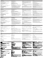
Hardware Installation
B
Installation of the VS0201 / VS0401 is simply a matter of plugging in the
appropriate cables.
To install the switch, refer to the installation diagram as you perform the
following steps:
1. Use a VGA/Audio cable to connect the VGA/Audio input of the video
display and speaker devices to the VGA/Audio output ports on the
rear of the VS0201 / VS0401.
2. Use VGA/Audio cables to connect the VGA/Audio output ports on
the source device(s) to the VGA/Audio input ports on the VS0201 /
VS0401. Two/Four VGA/Audio input ports are located on the rear of
the switch.
3. Use a grounding wire to ground the unit by connecting one end of
the wire to the grounding terminal, and the other end of the wire to a
suitable grounded object.
VS0201/VS0401 Vue arrière
1. Prise de terre
2. Port série RS-232
3. Port du récepteur infrarouge externe
4. Entrée vidéo/audio
5. Prise d’alimentation
6. Sortie vidéo/audio
Installation du matériel
B
L’installation du VS0201 / VS0401 se résume simplement à connecter
les câbles appropriés.
Pour installer le commutateur, reportez-vous au schéma d'installation
pour effectuer les étapes suivantes :
1. Utilisez un câble VGA/audio pour relier l’entrée VGA/audio du
périphérique d’affichage et des haut-parleurs aux ports de sortie
VGA/audio situés à l’arrière du VS0201 / VS0401.
2. Utilisez des câbles VGA/audio pour relier les ports de sortie VGA/
audio du ou des périphériques sources aux ports d’entrée VGA/
audio du commutateur VS0201 / VS0401. Deux/quatre ports d’entrée
VGA/audio sont situés à l’arrière du commutateur.
3. Pour mettre l’unité à la terre, reliez une extrémité du câble à la borne
de terre et l'autre extrémité à un objet correctement mis à la terre.
VS0201/VS0401 Rückseitige Ansicht
1. Erdungsanschluss
2. Serieller RS-232-Port
3. Port für externen Infrarot-Empfänger
4. Grafik-/Audioeingang
5. Stromeingangsbuchse
6. Grafik- / Audio-Ausgang
Hardware installieren
B
Die Installation des VS0201 / VS0401 ist mit ein paar wenigen
Kabelanschlüssen erledigt.
Für die Durchführung der folgenden Installationsschritte für den Switch,
siehe das Installationsdiagramm:
1. Verbinden Sie die VGA-/Audio-Eingänge der Bildschirme und der
Lautsprecher mit den VGA-/Audio-Ausgängen auf der Rückseite des
VS0201 / VS0401. Verwenden Sie dazu je ein VGA-/Audiokabel.
2. Verbinden Sie die VGA-/Audio-Ausgänge der Signalquelle(n) mit den
VGA-/Audio-Eingängen am VS0201 / VS0401. Verwenden Sie dazu
je ein VGA-/Audiokabel. Auf der Rückseite des Switchs befinden sich
zwei bzw. vier VGA-/Audio-Eingänge.
3. Erden Sie die Einheit mithilfe eines Erdleiters. Verbinden Sie dazu
das eine Ende des Leiters mit der Erdungsschelle und das andere
Ende mit einem geerdeten Gegenstand.
VS0201/VS0401 Vista posterior
1. Toma de tierra
2. Puerto serie RS-232
3. Puerto para receptor de infrarrojos externo
4. Entrada gráfica/de audio
5. Entrada de alimentación
6. Salida gráfica/de audio
Instalar el hardware
B
La instalación del VS0201 / VS0401 es tan sencilla como conectar
unos cables.
Para instalar el conmutador, véase el diagrama de instalación cuando
vaya a efectuar los pasos listados a continuación:
1. Conecte las entradas de VGA/audio de las pantallas y los altavoces
a los puertos de salida de VGA/audio en el panel posterior del
VS0201 / VS0401. Para ello, utilice cables de VGA/audio.
2. Conecte los puertos de salida de audio/VGA de los dispositivos
fuente a los puertos de entrada de audio/VGA del VS0201 / VS0401.
Para ello, utilice cables de audio/VGA. En el panel posterior del
conmutador se encuentran dos/cuatro puertos de entrada de audio/
VGA.
3. Emplee un conductor de tierra para poner la unidad a masa. Para
ello, conecte un extremo del conductor al terminal de tierra del
equipo y el otro extremo a un objeto ya puesto a tierra.
VS0201/VS0401 Vista posteriore
1. Terminale di messa a terra
2. Porta seriale RS-232
3. Porta ricevitore IR esterno
4. Entrata video/audio
5. Presa d’alimentazione
6. Uscita video/audio
Installazione dell’hardware
B
L’installazione del VS0201/VS0401 si limita al collegamento dei cavi.
Per installare lo switch, fare riferimento all’illustrazione sull’installazione
mentre si eseguono i seguenti passaggi:
1. Utilizzare i cavi VGA/audio per collegare le porte in entrata VGA/
audio dei dispositivi di visualizzazione e degli altoparlanti alle porte
in uscita VGA/audio del VS0201/VS0401.
2. Utilizzare i cavi VGA/audio per collegare le porte in uscita VGA/audio
del/dei dispositivo/i sorgente alle porte in entrata VGA/audio del
VS0201/VS0401. Sul retro dello switch si trovano due/quattro porte
VGA/audio in entrata.
3. Utilizzare un filo apposito per mettere a terra l’unità collegando
un’estremità del filo all’apparecchio da mettere a terra e l’altra
estremità a un dispositivo dotato di adeguata messa a terra.
4. Inserire la spina dell’alimentatore in dotazione in una presa di
corrente CA, quindi inserire il cavo dell’alimentatore nella presa
d’alimentazione del VS0201/VS0401.
4. Plug the provided power adapter into an appropriate AC power
source; plug the power adapter cable into the power jack on the
VS0201 / VS0401.
5. (Optional) To control the VS0201 / VS0401 system through the RS-
232 port, connect the hardware/software controller here.
6. (Optional) Connect the IR Receiver into the External IR Receiver
Input Port.
The installation is complete, you may power on the display and source
devices.
Note: The VS0201 and VS0401 installations are the same, with the
only
difference being that the VS0401 has two additional source
ports.
Installing the RS-232 Controller
In order to use the RS-232 serial interface to attach a high-end
controller (such as a PC) to the VS0201 / VS0401, use a RS-232 serial
cable. The end connecting to the VS0201 / VS0401 should have a 9-pin
male connector. Refer to step 5 on the diagram.
Operation
The VS0201 / VS0401 2/4-Port VGA Switch with Audio offers easy
source device selection with either the front panel pushbuttons, IR
remote control, or RS-232 serial interface.
4. Branchez une extrémité de l’adaptateur secteur fourni sur une prise
de courant adaptée et l’autre extrémité sur la prise d’alimentation du
commutateur VS0201 / VS0401.
5. (Facultatif) Pour commander le système VS0201 / VS0401 par le
biais du port RS-232, connectez ici le contrôleur matériel/logiciel.
6. (Facultatif) Connectez le récepteur infrarouge au port d’entrée pour
récepteur infrarouge externe
L’installation est terminée. Vous pouvez à présent allumer les
périphériques d'affichage et les périphériques sources.
Remarque : Les installations du VS0201 et VS0401 sont identiques, à
la seule différence que le VS0401 possède deux ports de
source supplémentaires.
Configuration du contrôleur RS-232
Pour utiliser l’interface série RS-232 pour la connexion d’un contrôleur
haut de gamme (ordinateur, par exemple) au VS0201 / VS0401, utilisez
un câble série RS-232. L’extrémité du câble à relier au VS0201 /
VS0401 doit être équipée d’un connecteur mâle à 9 broches. Référez-
vous à l’étape 5 du schéma.
4. Schließen Sie das mitgelieferte Netzteil an eine stromführende
Steckdose an, und verbinden Sie das Kabel des Netzteils mit dem
VS0201 / VS0401.
5. (Optional) Um den VS0201 / VS0401 über den RS-232-Port steuern
zu können, schließen Sie hier den Hardware-/Software-Controller an.
6. (Optional) Schließen Sie den Infrarot-Empfänger an die
Infrarotbuchse an.
Damit ist die Installation abgeschlossen. Jetzt können Sie die
Anzeigegeräte und die Signalquellen einschalten.
Hinweis:
Die Installation der Geräte VS0201 und VS0401 unterscheidet
sich nicht. Der einzige Unterschied besteht darin, dass der
VS0401
zwei zusätzliche Ports für Signalquellen besitzt.
RS-232-Steuereinheit anschließen
Um die serielle RS-232-Schnittstelle mit einer Hochleistungs-
Steuereinheit (z.B. einem PC) für den VS0201 / VS0401 einzusetzen,
verwenden Sie ein serielles RS-232-Kabel. Das eine Ende des Kabels
sollte einen 9-poligen Stecker besitzen. Siehe Schritt 5 im Diagramm.
Bedienung
Der 2-/4-Port-VGA-Switch mit Tonübertragung VS0201 / VS0401
bietet eine einfache Auswahl der gewünschten Signalquelle über die
4. Conecte un extremo del adaptador de alimentación incluido a
una toma eléctrica y el otro extremo a la entrada de corriente del
conmutador VS0201 / VS0401.
5. (Opcional) Para controlar el VS0201 / VS0401 a través del puerto
RS-232, conecte la controladora de hardware/software aquí.
6. (Opcional) Conecte el receptor de infrarrojos al puerto para el
receptor de infrarrojos externo.
La instalación ha concluido. A continuación podrá encender las
pantallas y los dispositivos fuente de señal.
Nota: La instalación es idéntica para las unidades VS0201 y VS0401.
La única diferencia es que el VS0401 posee dos puertos
adicionales para conectar fuentes de señal.
Instalar la controladora RS-232
Para utilizar la interfaz serie RS-232 para la conexión de una
controladora de altas prestaciones (p.ej. una computadora) al VS0201
/ VS0401, use un cable serie RS-232. El extremo del cable que se
conecta al VS0201 / VS0401 debe disponer de un conector macho de
9 patillas. Véase el paso 5 del diagrama.
Funcionamiento
El conmutador VGA de 2/4 puertos con transmisión de audio VS0201 /
VS0401 permite seleccionar fácilmente el dispositivo fuente mediante
5. (Opzionale) Per modificare le impostazioni di sistema del VS0201/
VS0401 tramite porta RS-232, collegare qui il controller hardware/
software.
6. (Opzionale) Collegare il ricevitore a infrarossi alla porta d’entrata del
ricevitore a infrarossi esterno
A questo punto l’installazione è completata ed è possibile accendere lo
schermo e i dispositivi sorgente.
Nota: le installazioni per il VS0201 e VS0401 sono le stesse, l’unica
differenza sono le due porte sorgenti in più del VS0401.
Installazione del controller RS-232
Per collegare un controller sofisticato (come un PC) al VS0201/VS0401
tramite l’interfaccia seriale RS-232, utilizzare un cavo seriale RS-232.
L’estremità da collegare al VS0201/VS0401 dovrà essere dotata di un
connettore maschio a 9 pin. Fare riferimento al punto 5 della figura.
Funzionamento
Lo switch VS0201/VS0401 a 2/4 porte VGA consente una facile e
flessibile selezione del dispositivo sorgente tramite i pulsanti anteriori, il
telecomando o l’interfaccia seriale RS-232.
Selezione manuale della porta
Per selezionare un dispositivo sorgente da visualizzare sullo schermo
Manual Source Selection
To select the source device to view on your VGA display, press the front
panel pushbutton that corresponds to the port it is connected to.
Remote Control Source Selection
To select a source device with the remote control, press the number
button that corresponds to the port it is connected to. Alternatively, you
may also cycle through the source devices by pushing the Port Up and
Port Down buttons on the remote control unit.
RS-232 Serial Interface Source Selection
The VS0201 / VS0401’s built-in bi-directional RS-232 serial interface
allows system control through a high-end controlle
r, PC, and/or home
automation / home theater software package.
Fonctionnement
Le commutateur VGA à 2/4 ports avec audio VS0201 / VS0401 permet
de sélectionner rapidement et simplement le périphérique source désiré
à l’aide des boutons du panneau avant, de la télécommande ou de
l’interface série RS-232.
Sélection de source manuelle
Pour sélectionner manuellement le périphérique source sont vous
souhaitez afficher les signaux sur votre périphérique d’affichage VGA,
appuyez sur le bouton du panneau avant correspondant au port auquel
il est connecté.
Sélection de la source par télécommande
Pour sélectionner un périphérique source à l’aide de la télécommande,
appuyez sur la touche numérique correspondant au port auquel il
est connecté. Vous pouvez également faire défiler les périphériques
sources en appuyant sur les boutons Port Up et Port Down de la
télécommande.
Sélection de la source par l’interface série RS-232
L’interface série RS-232 bidirectionnelle intégrée au VS0201 / VS0401
permet le contrôle du système par un contrôleur haut de gamme, un
ordinateur et/ou un logiciel de domotique ou de home cinéma.
vorderseitigen Drucktasten, über die Infrarot-Fernbedienung oder über
die serielle RS-232-Schnittstelle.
Signalquelle manuell auswählen
Um eine Signalquelle zur Anzeige auf Ihrem VGA-Bildschirm
auszuwählen, drücken Sie die vorderseitigen Drucktaste, die den Port
des angeschlossenen Gerätes darstellt.
Signalquelle per Fernbedienung auswählen
Um eine Signalquelle über die Fernbedienung auszuwählen, drücken
Sie die Zifferntaste mit der Nummer, die den Port des angeschlossenen
Gerätes darstellt. Alternativ dazu können Sie die Taste Port auf/ab auf
der Fernbedienung drücken, um zyklisch zwischen den Signalquellen
umzuschalten.
Signalquelle über serielle RS-232-Schnittstelle auswählen
Über die bidirektionale RS-232-Schnittstelle des VS0201 / VS0401
ist die Systemsteuerung über einen hochwertigen Controller, PC bzw.
Hausautomatisierungs- bzw. Heimkinosoftware möglich.
los botones del panel frontal, el mando a distancia por infrarrojos o la
interfaz serie RS-232.
Seleccionar la fuente de señal manualmente
Para seleccionar un dispositivo fuente para mostrarlo en su pantalla
VGA, pulse el botón del panel frontal que corresponde al puerto donde
tiene conectado el dispositivo en cuestión.
Seleccionar la fuente de señal a través del mando a distancia
Para seleccionar un dispositivo fuente con el mando a distancia, pulse
la tecla numérica que corresponde al número del puerto donde tiene
conectado el dispositivo en cuestión. También puede pulsar los botones
Port Up y Port Down del mando a distancia para alternar cíclicamente
entre las diferentes fuentes de señal.
Seleccionar la fuente de señal vía interfaz serie RS-232
La interfaz serie RS-232 bidireccional incorporada del VS0201 /
VS0401 permite controlar el sistema a través de una controladora de
altas prestaciones, el PC y/o un software de control de domótica / cine
en casa.
VGA, premere il pulsante sul pannello anteriore corrispondente alla
porta a cui è collegato il dispositivo.
Selezione della sorgente da telecomando
Per selezionare un dispositivo sorgente tramite telecomando, premere
il pulsante numerato corrispondente alla porta a cui è collegato il
dispositivo. In alternativa, è possibile spostarsi circolarmente fra i
dispositivi sorgente disponibili premendo i pulsanti Porta Su/Porta Giù
sul telecomando.
Selezione della sorgente tramite interfaccia seriale RS-232
L'interfaccia RS-232 bidirezionale incorporata nel VS0201/VS0401
consente di controllare il sistema tramite un sofisticato controller, PC, e/
o pacchetto software per la domotica/home theater.
B
Package Contents
1 VS0201 / VS0401 2/4-Port VGA Switch with Audio
1 Power Adapter
1 User Instructions
Important Notice
Considering environmental protection,
ATEN does not provide a fully printed user
manual for this product. If the information
contained in the Quick Start Guide is not
enough for you to configure and operate
your product, please visit our website
www.aten.com, and download the full user
manual.
Online Registration
http://eservice.aten.com
Technical Phone Support
International:
886-2-86926959
North America:
1-888-999-ATEN Ext: 4988
United Kingdom:
44-8-4481-58923
All information, documentation, and
specifications contained in this media
are subject to change without prior
notification by the manufacturer. Please
visit our website to find the most up to
date version.
VS0201 Front View VS0401 Front View
VS0201 Rear View VS0401 Rear View
Hardware Installation
© Copyright 2012 ATEN
®
International Co., Ltd.
ATEN and the ATEN logo are trademarks of ATEN International Co., Ltd. All rights reserved.
All other trademarks are the property of their respective owners.
This product is RoHS compliant.
Part No. PAPE-1223-810G
Printing Date: 08/2012
2/4-Port VGA Switch with Audio
Quick Start Guide
VS0201 / VS0401
5
4
3
2
1
OR
6
1
2
3 4
4
6
2
1
5
3
1
2
3 4
4
6
2
1
5
3
VS0201 / VS0401 2/4-Port VGA Switch with Audio
www.aten.com
Commutateur VGA à 2/4 ports avec audio VS0201 / VS0401
www.aten.com
VS0201 / VS0401 2/4-Port-VGA-Switch mit Tonübertragung
www.aten.com
VS0201 / VS0401 Conmutador VGA de 2/4 puertos con transmisión de audio
www.aten.com
Switch VS0201 / VS0401 a 2/4 porte VGA con audio
www.aten.com
A
Hardware Review
La page est en cours de chargement...
-
 1
1
-
 2
2


ATEN VS0201 Guide de démarrage rapide
- Taper
- Guide de démarrage rapide
- Ce manuel convient également à
dans d''autres langues
- italiano: ATEN VS0201 Guida Rapida
- English: ATEN VS0201 Quick start guide
- español: ATEN VS0201 Guía de inicio rápido
- Deutsch: ATEN VS0201 Schnellstartanleitung
- русский: ATEN VS0201 Инструкция по началу работы
- português: ATEN VS0201 Guia rápido
- 日本語: ATEN VS0201 クイックスタートガイド
Documents connexes
-
ATEN VB100 Guide de démarrage rapide
-
ATEN VS0102 Guide de démarrage rapide
-
-
-
-
-
-
ATEN VS481B Guide de démarrage rapide
-
ATEN VE500R Guide de démarrage rapide
-
ATEN VS1508 Guide de démarrage rapide