
A/V Over Cat 5 Extender
© Copyright 2010 ATEN
®
International Co., Ltd.
ATEN and the ATEN logo are trademarks of ATEN International Co., Ltd. All rights reserved. All other
trademarks are the property of their respective owners.
This product is RoHS compliant.
Manual Part No. PAPE-1285-120G Printing Date: 07/2010
VE500 A/V Over Cat 5 Extender User Guide
Prolongateur A/V VE500 Cat 5 - Guide d'utilisation
VE500 Audio-Video-Verlängerung Over Cat 5 Benutzerhandbuch
VE500 Alargador A/V sobre Cat. 5 Manual de usuario
VE500T / VE500R / VE500RQ
User Guide
www.aten.com
www.aten.com
www.aten.com
www.aten.com
Configuration minimale
Périphérique source
Le composant suivant doit être installé sur le périphérique source ou sur l'ordinateur agissant
en tant que source du contenu VGA/audio :
• Connecteur HDB-15
• Port haut-parleurs (en option)
Transmetteur
• Transmetteur ATEN VE500T A/V Cat 5
• Commutateur matriciel A/V ATEN VM0808T 8 x 8 Cat 5
Récepteur
• Récepteur ATEN VE500R A/V Cat 5
• Récepteur ATEN VE500RQ A/V avec fonction de compensation de signal
Périphérique(s) d’affichage
• Un périphérique d’affichage VGA, SVGA, XGA, SXGA, UXGA, WUXGA ou multisync ou un
récepteur équipé d'un connecteur HDB-15
• Haut-parleurs (en option)
Câbles
• Utilisez un câble VGA/Audio/RS-232 pour connecter le périphérique source au transmetteur
(VE500T / VM0808T)
• Utilisez un câble de catégorie 5e pour connecter le transmetteur (VE500T / VM0808T) au
récepteur VE500R / VE500RQ
• Utilisez un câble VGA/Audio/RS-232 pour connecter le VE500R / VE500RQ au périphérique
d’affichage
Remarque : les câbles ne sont pas fournis avec l’appareil VE500R / VE500RQ.
Description du matériel (A)
A. VE500T – Vue avant
1. Port d’entrée vidéo
2. Port d'entrée audio stéréo
3. Port série RS-232
4. Voyant d’alimentation
Voraussetzungen
Signalquelle
Auf den Signalquellen oder Computern, die das VGA-/Audiosignal senden, muss mindestens
Folgendes installiert sein:
• HDB-15-Anschluss
• Lautsprecherbuchse (optional)
Sender
• ATEN VE500T Audio-Video-Sender Over Cat 5
• ATEN VM0808T 8 x 8 Audio-Video-Matrix-Switch für Kat. 5-Kabel
Empfänger
• ATEN VE500R Audio-Video-Empfänger Over Cat 5
• ATEN VE500RQ Audio-Video-Empfänger Over Cat 5 mit Signalkompensation
Anzeigegerät(e)
• Ein VGA-, SVGA-, XGA-, SXGA-, UXGA-, WUXGA- oder Multisync-Anzeigegerät bzw.
–Empfangsgerät mit HDB-15-Buchse
• Lautsprecher (optional)
Kabel
• Verbinden Sie die Signalquelle mit dem Sender. Verwenden Sie dazu je ein VGA-, Audio-
und RS-232-Kabel.
• Verbinden Sie den Sender (VE500T / VM0808T) über ein Kat. 5e-Kabel mit dem VE500R- /
VE500RQ-Empfänger.
• Verbinden Sie den VE500R / VE500RQ mit dem Anzeigegerät. Verwenden Sie dazu je ein
VGA-, Audio- und RS-232-Kabel.
Hinweis: Die Kabel sind nicht im Lieferumfang des VE500R / VE500RQ enthalten.
Hardwareübersicht (A)
A. Vorderseitige Ansicht des VE500T
1. Grafikeingang
2. Stereo-Audio-Eingang
3. Serieller RS-232-Port
4. LED-Betriebsanzeige
Requisitos
Dispositivo fuente
En los dispositivos fuente de señal de audio/VGA u ordenadores que se conectan al equipo
debe estar instalado lo siguiente:
• Conector HDB-15
• Enchufe para altavoces (opcional)
Transmisor
• Transmisor A/V sobre Cat. 5 ATEN VE500T
• Conmutador A/V de matriz 8 x 8 ATEN VM0808T de Cat. 5
Receptor
• Receptor A/V sobre Cat. 5 ATEN VE500R
• Receptor A/V sobre Cat. 5 ATEN VE500RQ con compensación de señal
Dispositivo(s) de visualización
• Un dispositivo de visualización VGA, SVGA, XGA, SXGA, UXGA, WUXGA o multisync o un
receptor con un conector HDB-15
• Altavoces (opcional)
Cables
• Conecte el dispositivo fuente al transmisor (VE500T / VM0808T). Para ello, conecte un
cable VGA/audio/RS-232.
• Utilice un cable de Cat. 5e para conectar el transmisor (VE500T / VM0808T ) al receptor
VE500R / VE500RQ.
• Conecte el VE500R / VE500RQ al dispositivo de visualización. Para ello, conecte un cable
VGA/audio/RS-232.
Nota: los cables no vienen incluidos en el paquete del VE500R / VE500RQ.
Presentación del hardware (A)
A. VE500T – Vista frontal
1. Puerto de entrada de señal gráfica
2. Entrada de audio estéreo
3. Puerto serie RS-232
4. Indicador LED de alimentación
C. VE500R – Vue avant
1. Port série RS-232
2. Bouton de compensation de l'image (augmenter)
3. Bouton de compensation de l'image (diminuer)
4. Voyant de compensation de l'image
5. Voyant de liaison
6. Voyant d’alimentation
E. VE500R/RQ – Vue arrière
1. Prise d’alimentation
2. Port de sortie audio symétrique
3. Port de sortie audio stéréo
4. Port d’unité à unité (E/S distante)
5. Port de sortie vidéo
Installation du matériel (B)
1. Utilisez un câble VGA/audio pour connecter l’ordinateur ou les ports de sortie audio/
vidéo d’une autre source audio/vidéo au port d’entrée vidéo et aux ports d’entrée audio
symétrique/stéréo du transmetteur (panneau avant).
2. Si vous utilisez un périphérique série RS-232 dans votre installation, utilisez un câble série
pour connecter le PC au port femelle RS-232 du transmetteur (panneau avant).
3. Branchez le câble VGA de l’écran local sur le port de sortie vidéo du transmetteur (panneau arrière).
4. Raccordez les haut-parleurs stéréo locaux au mini-port de sortie audio stéréo du
transmetteur (panneau arrière)
5. Pour les systèmes audio symétriques, utilisez un câble audio symétrique (non fourni) pour
connecter votre source audio symétrique au connecteur d’entrée audio à vis imperdable, 5
pôles, du transmetteur (panneau arrière). Raccordez vos haut-parleurs audio symétrique
locaux au connecteur de sortie audio à vis imperdable, 5 pôles, du transmetteur (panneau arrière).
Remarque : si les deux sources audio sont connectées, la source audio stéréo est prioritaire.
6. Branchez l’un des adaptateurs secteur fournis sur une prise de courant et raccordez le
câble d’alimentation de l’adaptateur à la prise d’alimentation du transmetteur (panneau arrière).
7. Utilisez un câble de catégorie 5e pour relier le port d’E/S distante (Remote I/O) du
transmetteur (panneau arrière) et le port d’E/S distante (Remote I/O) du récepteur (panneau arrière).
8. Branchez le câble VGA de l’écran distant sur le port de sortie vidéo du récepteur (panneau arrière).
9. Raccordez les haut-parleurs stéréo distants au mini-port de sortie audio du récepteur
(panneau arrière) ou les haut-parleurs audio symétrique distants au connecteur de sortie
audio à vis imperdable, 5 pôles, du récepteur (panneau arrière).
10. Branchez les autres adaptateurs secteur sur une prise de courant et raccordez le câble
d’alimentation de l’adaptateur à la prise d’alimentation du récepteur (panneau arrière).
11. Connectez le périphérique série RS-232 au port série RS-232 situé sur le panneau avant du récepteur.
Remarque : le câble VGA/audio et le câble de catégorie 5e ne sont pas fournis avec le
produit. Ils doivent être achetés séparément.
C. Vorderseitige Ansicht des VE500R
1. Serieller RS-232-Port
2. Bildkompensations-Drucktaste +
3. Bildkompensations-Drucktaste -
4. Bildkompensations-LED
5. Verbindungsanzeige
6. LED-Betriebsanzeige
E. Rückseitige Ansicht des VE500R/RQ
1. Stromeingangsbuchse
2. Symmetrischer Audio-Ausgang
3. Stereo-Audio-Ausgang
4. Anschluss für Gerät an Gerät (E/A für Gegenstelle)
5. Grafikausgang
Hardware installieren (B)
1. Verbinden Sie die Audio-/Grafikausgänge des Computers oder der betreffenden Signalquelle
mit dem Eingang Video In und den symmetrischen Audio-Eingängen (Vorderseite) am Sender.
Verwenden Sie dazu je ein VGA- und ein symmetrisches Audio-Kabel.
2. Wenn Sie auch serielle RS-232-Geräte installieren möchten, verbinden Sie den PC mit einer RS-
232-Buchse des Empfängers (Vorderseite).
3. Schließen Sie das VGA-Kabel des lokalen Anzeigegerätes an den Grafik-Ausgang Video Out
(Rückseite) des Senders an.
4. Schließen Sie die lokalen Stereo-Lautsprecher an den Mini-Stereo-Ausgang Audio Out
(Rückseite) des Senders an.
5. Bei Verwendung symmetrischer Audiosysteme schließen Sie ein symmetrisches Audiokabel (nicht
im Lieferumfang enthalten) an den 5-poligen, verschraubbaren Audio-Eingang (Rückseite) des
Senders an. Schließen Sie in diesem Fall die lokalen, symmetrischen Stereo-Lautsprecher an den
5-poligen, verschraubbaren Audio-Ausgang Audio Out (Rückseite) des Senders an.
Hinweis : Wenn Sie zwei Tonquellen anschließen, erhält die Stereo-Audio-Quelle Priorität.
6. Verbinden Sie das eine Ende des mitgelieferten Netzteils mit einer Steckdose und das Netzkabel
mit der Stromeingangsbuchse des Senders (Rückseite).
7. Verbinden Sie den Anschluss Remote I/O (Rückseite) des Senders mit dem Anschluss Remote I/O
(Rückseite) des Empfängers.
8. Schließen Sie das VGA-Kabel des entfernten Anzeigegerätes an den Grafik-Ausgang Video Out
(Rückseite) des Empfängers an.
9. Verbinden Sie die Stereo-Lautsprecher der Gegenstelle mit dem Mini-Stereo-Ausgang Audio Out
(Rückseite) oder Ihre symmetrischen Lautsprecher mit der 5-poligen, verschraubbaren Buchse
Audio Out (Rückseite) am Empfänger.
10. Verbinden Sie die anderen Netzteile mit einer Steckdose; verbinden Sie das Stromkabel des
Adapter=s mit der Stromeingangsbuchse des Empfängers (Rückseite).
11. Schließen Sie das serielle RS-232-Gerät an den seriellen RS-232-Anschluss auf der Vorderseite des
Empfängers an.
Hinweis : Die VGA-, Audio- und Kat. 5e-Kabel sind nicht im Lieferumfang enthalten. Sie
müssen sie separat erwerben.
C. VE500R – Vista frontal
1. Puerto serie RS-232
2. Botón de compensación de imagen +
3. Botón de compensación de imagen -
4. Indicador de compensación de imagen
5. Indicador de enlace (Link)
6. Indicador LED de alimentación
E. VE500R/RQ – Vista posterior
1. Entrada de alimentación
2. Salida de audio simétrica
3. Salida de audio estéreo
4. Puerto de conexión unidad a unidad (E/S remoto)
5. Salida de señal gráfica
Instalar el hardware (B)
1. Emplee un cable VGA/audio para conectar las salidas de audio/vídeo del ordenador o de otra
fuente de señal A/V a las entradas Video In y Audio In estéreo / simétricas (panel frontal) del
transmisor.
2. Si utiliza un dispositivo RS-232 en su instalación, conecte también el PC al puerto RS-232 serie del
transmisor (panel frontal). Para ello, emplee un cable RS-232 serie.
3. Conecte el cable VGA del monitor local al puerto Video Out del transmisor (panel posterior).
4. Conecte los altavoces estéreo locales al puerto Audio Out mini-estéreo del transmisor (panel
posterior).
5. Para sistemas de audio simétricos, conecte su fuente de sonido simétrica a la toma Audio In de 5
patillas con rosca (panel posterior). Conecte los altavoces simétricos locales al puerto Audio Out
de 5 patillas con rosca del transmisor (panel posterior).
Nota: Si conecta ambas fuentes de sonido, la fuente estéreo es la que tendrá la prioridad.
6. Conecte uno de los adaptadores de alimentación incluidos a una toma eléctrica y el cable de
alimentación del adaptador a la entrada de alimentación del transmisor.
7. Conecte el puerto Remote I/O (panel posterior) del transmisor al puerto Remote I/O del receptor
(panel posterior). Para ello, emplee un cable de Cat. 5e.
8. Conecte el cable VGA de la pantalla remota al puerto Video Out del receptor (panel posterior).
9. Conecte los altavoces estéreo remotos a la salida Audio Out mini-estéreo del receptor (panel
posterior). O conecte los altavoces simétricos a la salida Audio Out de 5 patillas con rosca del
receptor (panel posterior).
10. Conecte los demás adaptadores de alimentación a una toma eléctrica y el cable de alimentación del
adaptador a la entrada de alimentación del receptor.
11. Conecte el dispositivo serie RS-232 al puerto serie RS-232 del panel frontal del receptor.
Nota: el cable de VGA/Audio y el de Cat. 5e no están incluidos en el paquete. Deberá adquirirlos
por separado.
Utilisation
Contrôle de la compensation du signal sur l’appareil VE500R
• Réglage manuel : pour effectuer un réglage fin du signal vidéo, appuyez sur la touche plus (+)
pour augmenter la compensation du signal vidéo ou sur la touche moins (–) pour diminuer la
compensation du signal vidéo.
• Détection automatique : appuyez simultanément sur les deux touches (+ / –) pendant 2
secondes pour déclencher la fonction de détection automatique et effacer les réglages en mémoire.
Contrôle RVB et de la compensation du signal sur l’appareil VE500RQ
• Appuyez sur le bouton Couleur/+ puis relâchez-le pour entrer dans le mode de réglage de la
couleur Rouge. Utilisez (+) et (-) pour ajuster.
• Appuyez le bouton Couleur/+ et maintenez-le enfoncé pendant deux secondes pour faire
apparaître l'affichage à l'écran (lorsqu'aucune couleur n'est sélectionnée).
• Appuyez le bouton Couleur/+ et maintenez-le enfoncé pendant deux secondes pour modifier
la couleur ou régler la compensation (si sélectionnée). La séquence est R _ G _ B _ Video
Compensation _ exit _ R …
• Appuyez sur le bouton Couleur/+ et relâchez-le pour augmenter la valeur (retard /
compensation) lorsqu’une couleur / valeur de compensation est sélectionnée.
• Appuyez simultanément sur les boutons Couleur et Sélection et maintenez-les enfoncés
pour déclencher la fonction de détection automatique (ajuste les couleurs R / V / B et la
compensation automatiquement) et effacer les réglages en mémoire.
• Appuyez sur le bouton Sélection/– puis relâchez-le pour entrer dans le mode de réglage de la
couleur Rouge. Utilisez (+) et (–) pour ajuster.
• Appuyez sur le bouton Sélection/– et relâchez-le pour diminuer la valeur (retard /
compensation) lorsqu’une couleur / valeur de compensation est sélectionnée
Voyant d'état
Caractéristiques techniques
Bedienung
Bildkompensation am VE500R
• Manuelle Kompensation - Falls es erforderlich wird, das Bildsignal nachzujustieren, drücken
Sie die Plustaste (+), um die Bildkompensation zu erhöhen bzw. die Minustaste (-), um sie
zu verringern.
• Automatische Kompensation - Halten Sie beide Tasten (+ / –) 2 Sekunden lang gedrückt, um
eine automatische Abstimmung durchzuführen und die zuvor abgespeicherten Werte zu löschen.
RGB- und –Bildkompensation am VE500RQ
• Drücken Sie die Taste Color/+, und lassen Sie sie los, um die Einstellfunktion der Farbe Rot
aufzurufen. Drücken Sie die Tasten (+) bzw. (-), um den gewünschten Wert einzustellen.
• Halten Sie die Taste Color/+ zwei Sekunden lang gedrückt, um das OSD-Bildschirmmenü
einzublenden (sofern keine Farbeinstellfunktion ausgewählt wurde).
• Halten Sie die Taste Color/+ zwei Sekunden lang gedrückt, um zwischen der
Farbeinstellfunktion und Bildkompensation umzuschalten (sofern ausgewählt). Die
Reihenfolge ist R _ G _ B _ Bildkompensation _ Beenden _ R …
• Drücken Sie die Taste Color/+ bei ausgewählter Farbeinstellfunktion, und lassen Sie sie los,
um den Wert (Laufzeit/Kompensation) zu erhöhen.
• Drücken und halten Sie die Tasten Color und Select gleichzeitig, um eine automatische
Abstimmung durchzuführen und die gespeicherten Werte zu löschen. Dabei wird die RGB-
Kompensation automatisch durchgeführt.
• Drücken Sie die Taste Select/–, und lassen Sie sie los, um die Einstellfunktion der Farbe Rot
aufzurufen. Drücken Sie die Tasten (+) bzw. (-), um den gewünschten Wert einzustellen.
• Drücken Sie die Taste Select/– bei ausgewählter Farbeinstellfunktion, und lassen Sie sie
los, um den Wert (Laufzeit/Kompensation) zu verringern.
LED-Anzeige
Technische Daten
Funcionamiento
VE500R Control de compensación
• Compensación manual - si tuviera que efectuar un ajuste fino de la señal gráfica, pulse el
botón más (+) para aumentar la compensación de la señal gráfica o pulse el botón menos (-) para reducirla.
• Compensación automática - mantenga pulsados ambos botones (+ / –) durante 2 segundos
para activar la detección automática y borrar los ajustes guardados.
VE500RQ Control RGB y de compensación
• Pulse y suelte el botón Color/+ para acceder a la función de ajuste para el color rojo. Pulse
los botones (+) y (-) para ajustar el valor deseado.
• Mantenga pulsado el botón Color/+ durante dos segundos para abrir el menú en pantalla
(cuando no tenga seleccionada ninguna función de ajuste de color).
• Mantenga pulsado el botón Color/+ durante dos segundos para cambiar entre el ajuste
de color o de compensación (cuando tenga alguna de estas funciones seleccionada). La
secuencia es R _ V _ A _ Compensación de imagen _ salir _ R …
• Pulse y suelte el botón Color/+ para incrementar el valor (tiempo de propagación/
compensación) cuando tenga seleccionado un color o la compensación.
• Mantenga pulsados los botones Color y Select simultáneamente para ejecutar
la compensación automática (ajusta la compensación para los colores R, V y A
automáticamente) y borra los valores almacenados.
• Pulse y suelte el botón Select/– para acceder a la función de ajuste para el color rojo. Pulse
los botones (+) y (-) para ajustar el valor deseado.
• Pulse y suelte el botón Select/– para reducir el valor (tiempo de propagación/compensación)
cuando tenga seleccionado un color o la compensación.
Indicador LED
VE500T
Alimentación VERDE Se enciende cuando la unidad está recibiendo corriente eléctrica.
VE500R
Alimentación VERDE Se enciende cuando la unidad está recibiendo corriente eléctrica.
Enlace NARANJA
Se ilumina cuando la conexión con el transmisor se ha establecido.
•
Parpadea cuando existe un problema de conexión con el transmisor.
•
Comp. de
imagen
AZUL Se enciende cuando está activada la función de compensación de imagen.
VE500RQ
A AZUL Parpadea cuando se ha seleccionado el color Azul. Pulse los botones +/- para ajustarlo.
•
V / Enlace
VERDE /
NARANJA
Se ilumina de color NARANJA cuando la conexión con el transmisor se ha establecido.
•
Parpadea de color NARANJA cuando existe un problema de conexión con el transmisor.
•
Parpadea de color VERDE cuando se ha seleccionado el color Verde. Pulse los botones +/-
•
para ajustarlo.
R /
Alimentación
ROJO /
VERDE
Se enciende de color VERDE cuando la unidad está recibiendo corriente eléctrica.
•
Parpadea de color ROJO cuando se ha seleccionado el color Rojo. Pulse los botones +/-
•
para ajustarlo.
Se ilumina de color ROJO (y el indicador + V /Enlace de color VERDE) para indicar que ha
•
seleccionado la compensación de imagen para efectuar su ajuste.
Especificaciones
B. VE500T – Vue arrière
1. Prise d’alimentation
2. Ports d’entrée/sortie audio symétrique
3. Port de sortie audio stéréo
4. Port d’unité à unité (E/S distante)
5. Port de sortie vidéo
B. Rückseitige Ansicht des VE500T
1. Stromeingangsbuchse
2. Symmetrische Audio-Ein-/Ausgänge
3. Stereo-Audio-Ausgang
4. Anschluss für Gerät an Gerät
(E/A für Gegenstelle)
5. Grafikausgang
B. VE500T – Vista posterior
1. Entrada de alimentación
2. Puertos de entrada/salida de audio simétricos
3. Salida de audio estéreo
4. Puerto de conexión unidad a unidad (E/S remoto)
5. Salida de señal gráfica
A B
Hardware Overview Hardware Installation
Package Contents
1 VE500T / VE500R / VE500RQ A/V Over Cat 5 Extender
1 Power Adapter
1 Rack Mount Kit
1 Terminal Block
1 Grounding Wire
1 User Guide
Online Registration
International:
http://support.aten.com
North America:
http://www.aten-usa.com/product_registration
Technical Phone Support
International:
886-2-86926959
North America:
1-888-999-ATEN Ext:4988
United Kingdom:
44-8-4481-58923
The following contains information that relates to China:
Requirements
Source Device
The following equipment must be installed on the source device or computer that acts as a
source of VGA/Audio content:
• HDB-15 connector
• Speaker port (optional)
Transmitter
• ATEN VE500T A/V Over Cat 5 Transmitter
• ATEN VM0808T 8 x 8 Cat 5 A/V Matrix Switch
Receiver
• ATEN VE500R A/V Over Cat 5 Receiver
• ATEN VE500RQ A/V Over Receiver with Deskew
Display Device(s)
• A VGA, SVGA, XGA, SXGA, UXGA, WUXGA or multisync display device or receiver with an
HDB-15 connector
• Speakers (optional)
Cables
•
Use a VGA/Audio/RS-232 cable connect the source device to the transmitter (VE500T / VM0808T)
• Use Cat 5e cable to connect the transmitter (VE500T / VM0808T /) to the VE500R /
VE500RQ receiver
• Use a VGA/Audio/RS-232 cable connect the VE500R / VE500RQ to the display device
Note: Cables are not provided in this VE500R / VE500RQ package.
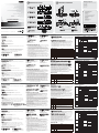
Hardware Review (A)
A. VE500T Front View
1. Video In Port
2. Stereo Audio In Port
3. RS-232 Serial Port
4. Power LED
C. VE500R Front View
1. RS-232 Serial Port
2. Picture Compensation Up Pushbutton
3. Picture Compensation Down Pushbutton
4. Picture Compensation LED
5. Link LED
6. Power LED
E. VE500R/RQ Rear View
1. Power Jack
2. Balanced Audio Out Port
3. Stereo Audio Out Port
4. Unit to Unit Port (Remote I/O)
5. Video Out Port
Hardware Installation (B)
1. Use a VGA/Audio cable to connect the computer or other audio/video source’s to the Transmitter’s
Video In port and stereo / balanced Audio In ports (front panel).
2. If you are using an RS-232 serial device in your installation, use a serial cable to connect
the PC to the Transmitter’s female RS-232 port (front panel).
3. Plug the local display’s VGA cable into the Transmitter’s Video Out port (rear panel).
4. Plug your local stereo speakers into the Transmitter’s mini stereo Audio Out port (rear panel).
5. For balanced audio, use a balanced audio cable (not supplied) to connect your balanced
audio source to the Transmitter’s 5-pole captive screw Audio In connector (rear panel).
Plug your local balanced audio speakers into the Transmitter’s 5-pole captive screw Audio
Out connector (rear panel).
Note: If both audio sources are connected, the stereo audio source has priority.
6. Plug one of the power adapters (supplied with this package) into an AC source; plug the
adapter’s power cable into the Transmitter’s Power Jack (rear panel).
7. Use Cat 5e to connect the Transmitter’s Remote I/O port (rear panel) and the Receiver’s
Remote I/O port (rear panel).
8. Plug the remote display’s VGA cable into the Receiver’s Video Out port (rear panel).
9. Plug the remote stereo speakers into the Receiver’s mini stereo Audio Out port (rear
panel), or the remote balanced audio speakers into the Receiver’s 5-pole captive screw
Audio Out connector (rear panel).
10. Plug the other power adapters into an AC source; plug the adapter’s power cable into the
Receiver’s Power Jack (rear panel).
11. Connect the RS-232 serial device to the RS-232 serial port on the Receiver’s front panel.
Note: VGA/Audio cable and Category 5e cable are not supplied with this package. These
require a separate purchase.
Operation
VE500R Compensation Control
• Manual Tuning – To fine-tune the video signal, press the plus (+) button to increase the video
signal compensation; press the minus (–) button to decrease the video signal compensation.
• Auto-detect – Press both buttons (+ / –) for 2 seconds to trigger the auto-detection function
and clear the stored the settings.
VE500RQ RGB and Compensation Control
• Press and release Color/+ button to enter Red color mode. Use (+) and (–) to adjust.
• Press and hold Color/+ button for two seconds to invoke the OSD (when no color is selected).
• Press and hold Color/+ button for two seconds to change the color mode or compensation
(when selected). The sequence is R _ G _ B _ Video Compensation _ exit _ R …
• Press and release Color/+ button to increase value (delay time / compensation) when any
color / compensation is selected.
• Press and hold both Color and Select buttons simultaneously to trigger the auto-detect
function (adjusts R/G/B/Compensation automatically) and clear the stored settings.
• Press and release Select/– button to enter Red color mode. Use (+) and (–) to adjust.
• Press and release Select/– button to decrease value (delay time / compensation) when any
color / compensation is selected.
LED Display
Specifications
B. VE500T Rear View
1. Power Jack
2. Balanced Audio In/Out Ports
3. Stereo Audio Out Port
4. Unit to Unit Port (Remote I/O)
5. Video Out Port
D. VE500RQ Front View
1. RS-232 Serial Port
2. Color Pushbutton
3. Select Pushbutton
4. Blue LED
5. Green / Link LED
6. Red / Power LED
D. VE500RQ – Vue avant
1. Port série RS-232
2. Bouton Couleur
3. Bouton de sélection
4. Voyant bleu
5. Voyant vert/de liaison
6. Voyant rouge/d’alimentation
D. Vorderseitige Ansicht des
VE500RQ
1. Serieller RS-232-Port
2. Farbeinstellungs-Drucktaste
3. Auswahl-Drucktaste
4. Blaue LED
5. Grün / Verbindungsanzeige
6. Rot / Betriebsanzeige
D. VE500RQ – Vista frontal
1. Puerto serie RS-232
2. Botón Color
3. Botón de selección
4. Indicador LED azul
5. Indicador verde / enlace
6. Indicador rojo / alimentación
F. All Units Side View
1. Grounding Terminal
F. Vue latérale de toutes les
unités
1. Prise de terre
F. Seitliche Ansicht aller
Geräte
1. Erdungsanschluss
F. Vista lateral de todos los
dispositivos
1. Toma de tierra
VE500T
Power GREEN Lights to indicate that the unit is receiving power.
VE500R
Power GREEN Lights to indicate that the unit is receiving power.
Link ORANGE
Lights steadily to indicate that the connection to the Transmitter is OK.
•
Flashes to indicate there is a problem with the connection to the Transmitter.
•
Pic. Comp. BLUE Lights to indicate that Picture Compensation has been activated.
VE500RQ
B BLUE Flashes to indicate Blue color is selected; use +/– Pushbutton to adjust.
•
G / Link GREEN /
ORANGE
Lights ORANGE steadily to indicate that the connection to the Transmitter is OK.
•
Flashes ORANGE to indicate there is a problem with the connection to the
•
Transmitter.
Flashes GREEN to indicate Green color is selected; use +/– Pushbutton to adjust.
•
R / Power
RED /
GREEN
Lights GREEN to indicate that the unit is receiving power.
•
Flashes RED to indicate Red color is selected; use +/– Pushbutton to adjust.
•
Lights RED steadily (+ G / Link LED lights GREEN) to indicate Video
•
Compensation will be selected for adjustment.
VE500T
Alimentation VERT S’allume pour indiquer que l’appareil est sous tension.
VE500R
Alimentation VERT S’allume pour indiquer que l’appareil est sous tension.
Liaison ORANGE
S’allume en continu pour indiquer que la connexion au transmetteur est correcte.
•
Clignote pour signaler un problème au niveau de la connexion au transmetteur.
•
Comp. image BLEU S’allume pour indiquer que la compensation de l’image a été activée.
VE500RQ
B BLEU
S’allume pour indiquer que la couleur Bleue est sélectionnée ; utilisez le bouton +/–
•
pour ajuster.
G / Liaison
VERT/
ORANGE
S‘allume (ORANGE) en continu pour indiquer que la connexion au transmetteur
•
fonctionne correctement.
Clignote (ORANGE) pour signaler un problème au niveau de la connexion au
•
transmetteur.
S’allume (VERT) pour indiquer que la couleur Verte est sélectionnée ; utilisez le bouton
•
+/– pour ajuster.
R /
Alimentation
ROUGE/
VERT
S’allume (VERT) pour indiquer que l’appareil est sous tension.
•
S’allume (ROUGE) pour indiquer que la couleur Rouge est sélectionnée ; utilisez le
•
bouton +/– pour ajuster.
S’allume (ROUGE) en continu (le voyant + G/Liaison s’allume en VERT) pour indiquer
•
que la Compensation vidéo va être sélectionnée pour être ajustée.
VE500T
Betrieb GRÜN Leuchtet, wenn das Gerät mit Strom gespeist wird.
VE500R
Stromversor
gung
GRÜN
Leuchtet, wenn das Gerät mit Strom gespeist wird.
Link ORANGE
Leuchtet stetig, wenn die Verbindung zum Sender hergestellt wurde.
•
Blinkt, wenn ein Problem mit der Verbindung zum Sender besteht.
•
Bildkomp. BLAU Leuchtet, wenn die Bildkompensation aktiviert wurde.
VE500RQ
B BLAU
Blinkt, wenn die Farbe Blau ausgewählt wurde; drücken Sie die Tasten +/-, um den
•
gewünschten Wert einzustellen.
G /
Verbindung
GRÜN /
ORANGE
Leuchtet ORANGE, wenn die Verbindung zum Sender hergestellt wurde.
•
Blinkt ORANGE, wenn ein Problem mit der Verbindung zum Sender besteht.
•
Blinkt GRÜN, wenn die Farbe Grün ausgewählt wurde; drücken Sie die Tasten +/-, um den
•
gewünschten Wert einzustellen.
R / Betrieb
ROT /
GRÜN
Leuchtet GRÜN, wenn das Gerät mit Strom gespeist wird.
•
Blinkt ROT, wenn die Farbe Rot ausgewählt wurde; drücken Sie die Tasten +/-, um den
•
gewünschten Wert einzustellen.
Leuchtet ROT, (+ G / Link-Anzeige leuchtet GRÜN), um anzuzeigen dass die
•
Bildkompensation zur Einstellung ausgewählt wurde.
Function VE500T VE500R VE500RQ
Connectors
Video In
1 x HDB-15 Male
(Blue)
N/A
Video Out 1 x HDB-15 Female (Blue)
Audio In
Stereo
1 x Mini Stereo Jack
Female (Green)
N/A
Balanced
1 x Captive Screw
Connector, 5 pole
(Green)
Audio
Out
Stereo 1 x Mini Stereo Jack Female (Green)
Balanced 1 x Captive Screw Connector, 5 pole (Green)
RS-232
1 x DB-9 Female
(Black)
1 x DB-9 Male (Black)
Unit to Unit 1 x RJ-45 Female
Power 1 x DC Jack (Black)
Switches
Compensation / Up
N/A
1 x Pushbutton
N/A
Compensation /
Down
1 x Pushbutton
Color / Up
N/A
1 x Pushbutton
Select / Down 1 x Pushbutton
LEDs
Power 1 (Green) 1 (Green)
N/A
Link
N/A
1 (Orange)
Picture
Compensation
1 (Blue)
B
N/A
1 (Blue)
G / Link 1 (Green/Orange)
R / Power 1 (Red/Green)
Video N/A
1920x1200@60Hz (30 m);
1600x1200 @60Hz
(150 m)
1920x1200 @60Hz (150 m);
1280x1024 @60Hz (300 m)
Power Consumption DC 5.3V, 2.98W DC 5.3V, 4.04W DC 5.3V, 5.03W
Environment
Operating Temp. 0–50°C
Storage Temp. -20–60°C
Humidity 0–80% RH, Non-condensing
Physical
Properties
Housing Metal
Weight 0.48 kg
Dimensions
(LxWxH)
20.00 x 8.00 x 2.50 cm
Function VE500T VE500R VE500RQ
Connecteurs
Entrée vidéo
1 connecteur HDB-
15 mâle (bleu)
N/D
Sortie vidéo 1 connecteur HDB-15 femelle (bleu)
Entrée
audio
Stéréo
1 mini-connecteur
stéréo femelle (vert)
N/D
Symé-
trique
1 connecteur à vis
imperdable, 5 pôles
(vert)
Sortie
audio
Stéréo 1 mini-connecteur stéréo femelle (vert)
Symé-
trique
1 connecteur à vis imperdable, 5 pôles (vert)
RS-232
1 connecteur DB-
9 femelle (noir)
1 connecteur DB-9 mâle (noir)
Port d’unité à unité 1 connecteur RJ-45 femelle
Alimentation 1 prise c.c. (noire)
Commuta-
teurs
Compensation/
Augmenter
N/D
1 bouton poussoir
N/D
Compensation/
Diminuer
1 bouton poussoir
Couleur/Augmenter
N/D
1 bouton poussoir
Sélection/Diminuer 1 bouton poussoir
Voyants
Alimentation 1 voyant (vert) 1 voyant (vert)
N/D
Liaison
N/D
1 voyant (orange)
Compensation de
l’image
1 voyant (bleu)
B
N/D
1 voyant (bleu)
G/Liaison 1 voyant (vert/orange)
R/Alimentation 1 voyant (rouge/vert)
Vidéo N/D
1920x1200 à 60 Hz (30 m);
1600x1200 à 60 Hz (150 m)
1920x1200à 60 Hz (150 m) ;
1280 x 1024 à 60Hz (300 m)
Consommation électrique CC 5,3 V, 2,98 W CC 5,3 V, 4,04 W CC 5,3 V, 5,03 W
Environne-
ment
Température de
fonctionnement
0 à 50 °C
Température de
stockage
-20 à 60 °C
Humidité Humidité relative de 0 à 80 %, sans condensation
Propriétés
physiques
Boîtier Métallique
Poids 0.48 kg
Dimensions
(Long x Larg x Haut)
20.00 x 8.00 x 2.50 cm
Funktion VE500T VE500R VE500RQ
Anschlüsse
Grafikeingänge
1 x HDB-
15 Männlein (blau)
--
Grafikausgänge 1 x HDB-15 Weiblein (blau)
Audio-
Eingänge
Stereo
1 x Mini-Stereo-
Buchse, Weiblein
(grün)
--
Symmetrisch
1 x
Schraubbuchse,
5-polig (grün)
Audio-
Ausgang
Stereo 1 x Mini-Stereo-Buchse, Weiblein (grün)
Symmetrisch 1 x Schraubbuchse, 5-polig (grün)
RS-232
1 x DB-9 Weiblein
(schwarz)
1 x DB-9 Männlein (schwarz)
Gerät an Gerät 1 x RJ-45 Weiblein
Stromversorgung 1 x Stromeingangsbuchse (schwarz)
Schalter
Kompensation / Aufwärts
--
1 x Drucktaster
--
Kompensation / Abwärts 1 x Drucktaster
Farbe / Aufwärts
--
1 x Drucktaster
Auswahl / Abwärts 1 x Drucktaster
LED-Anzeigen
Stromversorgung 1 (grün) 1 (grün)
--
Link
--
1 (orange)
Bildkompensation 1 (blau)
B
--
1 (blau)
G / Verbindung 1 (grün/orange)
R / Betrieb 1 (rot/grün)
Grafik --
1920x1200 bei 60Hz
(30 m);
1600x1200 bei 60Hz
(150 m)
1920x1200 bei 60Hz
(150 m) ;
1280 x 1024 bei 60Hz
(300 m)
Stromverbrauch 5,3 V=, 2,98 W 5,3 V=, 4,04 W 5,3 V=, 5,03 W
Umgebung
Betriebstemperatur 0-50 °C
Lagertemperatur -20-60 °C
Feuchtigkeit 0 -80% rel. Luftfeuchte, nicht kondensierend
Physische
Eigenschaften
Gehäuse Metall
Gewicht 0.48 kg
Abmessungen
(L x B x H)
20.00 x 8.00 x 2.50 cm
Funktion VE500T VE500R VE500RQ
Conectores
Entrada de señal
gráfica
1 conector HDB-
15 macho (azul)
--
Salida de señal
gráfica
1 conector HDB-15 hembra (azul)
Entra-
da de
audio
Estéreo
1 conector mini
estéreo hembra
(verde)
--
Simétrica
1 x toma con rosca,
5 patillas (verde)
Salida
de
audio
Estéreo 1 conector mini estéreo hembra (verde)
Simétrica 1 x toma con rosca, 5 patillas (verde)
RS-232
1 conector DB-
9 hembra (negro)
1 conector DB-9 macho (negro)
Puerto de unidad a
unidad
1 conector RJ-45 hembra
Alimentación 1 toma de c.c. (negra)
Conmuta-
dores
Compensación /
Subir
--
1 pulsador
--
Compensación /
Bajar
1 pulsador
Color / Arriba
--
1 pulsador
Seleccionar / Abajo 1 pulsador
Indicadores
LED
Alimentación 1 (verde) 1 (verde)
--
Enlace
--
1 (naranja)
Compensación de
imagen
1 (azul)
A
--
1 (azul)
V / Enlace 1 (verde/anaranjado)
R / Alimentación 1 (rojo/verde)
Señal gráfica --
1920x1200 a 60Hz (30 m);
1600x1200 a 60Hz (150
m)
1920x1200 a 60Hz (150 m);
1280x1024 a 60Hz (300 m)
Consumo 5,3V de c.c., 2,98 W 5,3 V de c.c., 4,04 W 5,3 V de c.c., 5,03 W
Entorno
Temperatura de
funcionamiento
0 a 50 °C
Temperatura de
almacenamiento
-20 a 60 °C
Humedad 0 a 80% de HR, sin condensar
Propiedades
físicas
Carcasa Metálica
Peso 0.48 kg
Dimensiones
(L x An x Al)
20.00 x 8.00 x 2.50 cm
1
1
12 3 4
AUDIO IN RS-232 POWERVGA IN
1 2 3 4
12345
VGA OUTREMOTE I/OAUDIO OUT
L+ L- R+ R-
AUDIO OUT
L+ L- R+ R-
AUDIO IN
1 2 3 4 5
1234
5
VGA OUTREMOTE I/OAUDIO OUTL+ L- R+ R-
AUDIO OUT
1 2 3 4 5
1 2 3 654
Picture Compensation
LINK POWER
1 2 3 4 5 6
1 2 3 654
1 2 3 4 5 6
A. VE500T Front View
B. VE500T Rear View
C. VE500R Front View
D. VE500RQ Front View
E. VE500R/RQ Rear View
F. All Units Side View
VGA OUTREMOTE I/OAUDIO OUTL+ L- R+R-
AUDIO OUT
VGA OUTREMOTE I/OAUDIO OUT
L+ L- R+ R-
AUDIO OUT
L+ L- R+ R-
AUDIO IN
1
11
Local
PC
VGA/Audio
Cable
Cat 5e Cable
2
5
657
89
9710
43
AUDIO IN RS-232 POWERVGA IN
AVR
barcode scannertouchscreen
1
2
3
89
45
56 7 7910
11
VE500T (Front View)
VE500T (Rear View)
VE500RQ (Front View)
VE500RQ/R (Rear View)

ȵɝĘɈǗඔڝǨٕă.1+3101+5/56
VE500 A/V Over Cat 5 ȨȯȹɆɳɀĘ ɦĘȶĘȬȤɉ
VE500 A/V Over Cat 5 ⤻⫰ᅻ ⏷⧴⫛ ཋ⪿ᠧ
VE500 A/V Over Cat 5 Extender – Guida per l’utente
www.aten.com
www.aten.com
Requisiti
Dispositivo sorgente
Sul computer sorgente del contenuto VGA/audio, o su quello che opera come tale, deve essere
installato il seguente dispositivo:
• Connettore HDB-15
• Uscita altoparlanti (opzionale)
Trasmettitore
• Trasmettitore ATEN VE500T A/V Over Cat 5
• Switch ATEN VM0808T 8 x 8 Cat 5 A/V Matrix
Ricevitore
• Ricevitore ATEN VE500T A/V Over Cat 5
• Ricevitore ATEN VE500RQ A/V Over con Deskew
Dispositivo/i di visualizzazione
• Un dispositivo di visualizzazione o un ricevitore VGA, SVGA, XGA, SXGA, UXGA, WUXGA o
Multisync con un connettore HDB-15
• Altoparlanti (opzionali)
Cavi
• Utilizzare un cavo VGA/Audio/RS-232 per collegare il dispositivo sorgente al trasmettitore (VE500T / VM0808T)
• Utilizzare un cavo Cat 5e per collegare il trasmettitore (VE500T / VM0808T /) al ricevitore VE500R / VE500RQ
• Utilizzare un cavo VGA/Audio/RS-232 per collegare il VE500R / VE500RQ al dispositivo di visualizzazione
Nota: I cavi non sono inclusi nella confezione del VE500R / VE500RQ .
Hardware (A)
A. VE500T – visione anteriore
1. Porta d’entrata video (video in)
2. Porta d’entrata audio stereo (audio in)
3. Porta seriale RS-232
4. LED d’alimentazione
ూɏĘɉȦȧȢש
߾ɇɐȤȹ
ɓɇȪ/ȪĘɇȣȪ߾؍ǵǷȘɇɐȤȹȋǬǼȳɳɔɥĘȿĘǙþϠӫǻשȟǬǤdzǑȘూ
ǙǏȗȋǦÿ
• D-sub15 ȢɊɭȰVGAȳɍȯȿĘ
• ȪĘɇȣȪ߾ɝĘɈĦȪɗȷɧɳħ
ɈɩɳȹɟɃȿĘ
• ATEN VE500T A/V Over Cat 5ɈɩɳȹɟɃȿĘ
• ATEN VM0808T 8 x 8 Cat 5 A/VɞɈɪɃȯȹȹȤɃɁ
ɬȷĘɐĘ
• ATEN VE500R A/V Over Cat 5ɬȷĘɐĘ
• ATEN VE500RQ ɇȹȭɥĘӟ౫ǚɬȷĘɐĘ
ݸɇɐȤȹ
• D-sub 15ɔɳȳɍȯȿȟݯDZVGA, SVGA, XGA, SXGA, UXGA, WUXGA, ɞɫɁȷɳȯɇȣȹɗɬȤ
• ȹɔĘȫĘĦȪɗȷɧɳħ
ȱĘɖɫ
• ߾ɇɐȤȹǵVE500T / VM0808TȟतষǦȘǬȎǻþVGA/ȪĘɇȣȪ/RS-232ȱĘɖɫǙూǴǦÿ
• VE500T / VM0808TǵVE500R / VE500RQȟतষǦȘǬȎǻCat 5e ɄȤȹɈɚȢȱĘɖɫǙూǴǦÿ
• VE500R / VE500RQǵݸɇɐȤȹȟतষǦȘǬȎǻþVGA/ȪĘɇȣȪ/RS-232ȱĘɖɫǙూ
ǴǦÿ
: ȱĘɖɫ์ǼVE500R / VE500RQǸଭہǢșdzǑȋǨȠÿݸǻȯȪɪɆȣȟDZǬȎ
ǸþǴǚȘǭǞژౠޑǷȱĘɖɫȟǡෟ̽ǜǭǢǑÿ
ɏĘɉȦȧȢз (A)
A. VE500TɕɭɳɈɓɥĘ
1. ɓɇȪɝĘɈ
2. ȹɆɬȪȪĘɇȣȪɝĘɈ
3. RS-232ȷɪȢɫɝĘɈ
4. ૣؓLED
⭾ቖ#▖㩗
ⓗ◯#⫰ㆣ
鲙넁녚렍鱉9*$$XGLRꌱ띑ꇚ뼍鱉ꭁ걙녚렍뿮냵뢩뺝뫥꾅ꗍ麑겑렍鷍꽩넽꽩꼱뼞鱽鲙
ವ+'%뢙髚뫥
ವ걙뻱뢙꿪ꬍ
⓬☫ᅻ
ವ$7(19(7$92YHU&DWꭖ겕韥
ವ$7(1907[&DW$9ꎙ뱭ꍢ걙걙낹렍
╣☫ᅻ
ವ$7(19(5$92YHU&DWꯍ겕韥
ವ$7(19(54$92YHUꯍ겕韥넩ꖭ덵韥끭韥ꚩ뇊韥鱚
ᡟ◯㡗᭓⪿#⫰ㆣ
ವ$9*$69*$;*$6;*$8;*$:8;*$PXOWLV\QF黉걙뻁ꆽ넩녚렍뿮냵+'%뢙髚뫥閵
넽鱉ꯍ겕韥
ವ걙뻱뢙꿪ꬍ
㉋⪿⅟
ವ9*$$XGLR56뢵넩Ꟊ냹ꩡ끞뼍꾡ꭁ걙녚렍꿵ꭖ겕韥9(7907ꌱ꾥陥뼍겢겑꿙
ವ&DWH뢵넩Ꟊ냹ꩡ끞뼍꾡ꭖ겕韥9(7907꿵ꯍ겕韥9(59(54ꌱ
꾥陥뼍겢겑꿙
ವ9*$$XGLR56뢵넩Ꟊ냹ꩡ끞뼍꾡ꯍ겕韥9(59(54ꌱ黉걙뻁ꆽ넩녚렍꾅
꾥陥뼍겢겑꿙
ⷦⱂ
뢵넩Ꟊ냵9(59(54볝멙덵꾅뇑險뼍덵껿걪鱽鲙
㩂ᧆ⯒⪞#ẖ⋚+D,
D1#YH833W#⭏ᶿ
ꟹ黉꿙넺ꇚ붡뱭
걙묁ꆽ꿙꿙黉꿙넺ꇚ붡뱭
56겑ꍡ꽱붡뱭
놹낅/('
C. VE500R – visione anteriore
1. Porta seriale RS-232
2. Pulsante Compensazione immagine su
3. Pulsante Compensazione immagine giù
4. LED della compensazione dell’immagine
5. LED di collegamento
6. LED d’alimentazione
E. VE500R/RQ – visione posteriore
1. Presa d’alimentazione
2. Porta d’uscita audio bilanciata (audio out)
3. Porta d’uscita audio stereo (audio out)
4. Porta da dispositivo a dispositivo (I/O remoto)
5. Porta d’uscita video (video out)
Installazione dell'hardware (B)
1. Utilizzare un cavo VGA/Audio per collegare il computer, o altre porte d’uscita audio/video della fonte
audio/video, alla porta Video In e alle porte Audio In stereo/bilanciata del trasmettitore.
2. Se nell’installazione si impiega un dispositivo seriale RS-232, usare un cavo seriale per collegare il
PC alla porta RS-232 femmina del trasmettitore (pannello anteriore).
3. Collegare il cavo VGA dello schermo locale alla porta Video Out del trasmettitore (pannello posteriore).
4. Collegare le casse stereo locali alla porta Audio Out mini stereo del trasmettitore (pannello posteriore).
5. Per ottenere un audio bilanciato, impiegare un cavo audio bilanciato (non in dotazione) per collegare
la fonte audio bilanciata al connettore Audio In a vite impedibile a 5 poli del trasmettitore (pannello
posteriore). Collegare le casse audio bilanciate al connettore Audio Out a vite imperdibile a 5 poli del
trasmettitore (pannello posteriore)
Nota: Se entrambe le fonti audio sono collegate, la priorità va alla fonte audio stereo.
6. Inserire uno degli alimentatori (in dotazione) in una presa di corrente CA, quindi inserire il cavo
dell’alimentatore nella presa d’alimentazione del trasmettitore (pannello posteriore).
7. Utilizzare il Cat 5e per collegare la porta I/O remoto del trasmettitore (pannello posteriore) alla porta
I/O remoto del ricevitore (pannello posteriore).
8. Collegare il cavo VGA dello schermo remoto alla porta Video Out del ricevitore (pannello posteriore).
9. Collegare le casse stereo remote alla porta Audio Out mini stereo del ricevitore (pannello posteriore)
o le casse audio bilanciate remote al connettore Audio Out a vite impedibile a 5 poli (pannello posteriore).
10. Inserire l’altro alimentatore in una presa di corrente CA, quindi inserire il cavo dell’alimentatore nella
presa d’alimentazione del ricevitore (pannello posteriore).
11. Collegare il dispositivo seriale RS-232 alla porta seriale RS-232 sul pannello anteriore del ricevitore.
Nota: Il cavo audio VGA e quello Cat 5e non sono acclusi alla confezione. Devono essere
acquistati separatamente.
C. VE500RɕɭɳɈɓɥĘ
1. RS-232ȷɪȢɫɝĘɈ
2. ЌޑࣽĦUpħɗɃȷɥɜȿɳ
3.
ЌޑࣽĦdownħɗɃȷɥɜȿɳ
4. ЌޑࣽĦUpħɗɃȷɥɜȿɳLED
5.
ɪɳȯLED
6.
ૣؓLED
E. VE500R/RQɪȢɓɥĘ
1. ૣؓȸɣɃȯ
2. ɐɩɳȹȪĘɇȣȪ߾ɝĘɈ
3. ȹɆɬȪȪĘɇȣȪ߾ɝĘɈ
4. ɦɋɃɈतষɝĘɈ(ɪɢĘɈI/O)
5.
ɓɇȪ߾ɝĘɈ
ɏĘɉȦȧȢȻɃɈȢɃɗ (B)
1. VGA/ȪĘɇȣȪȱĘɖɫȟෟǑdzþȳɳɔɥĘȿĘȋǬǼǪǻূǻ߾ɇɐȤȹǻɓɇȪ
ɝĘɈǵþȹɆɬȪȋǬǼɐɩɳȹȪĘɇȣȪɝĘɈȟतষǤdzǜǭǢǑÿ
2. RS-232ȷɪȢɫࣱؾȟܺǓࡸڝǼþȳɳɔɥĘȿĘǻȷɪȢɫɝĘɈǵþɈɩɳȹɟɃȿĘǻ
RS-232ȷɪȢɫɝĘɈȟतষǤdzǜǭǢǑÿ
3. VGA
ȱĘɖɫȟܺෟǤdzþɭĘȫɫǴܺෟǦȘɇȣȹɗɬȤǵɈɩɳȹɟɃȿĘǻɓɇȪ߾
ɝĘɈȟतষǤdzǜǭǢǑÿ
4. ɭĘȫɫǴܺෟǦȘȹɔĘȫĘȟþɈɩɳȹɟɃȿĘǻȹɆɬȪȪĘɇȣȪ߾ɝĘɈǸतষǤ
dzǜǭǢǑÿ
5. ɐɩɳȹȪĘɇȣȪतষȟڊǓࡸڝǼþɐɩɳȹȪĘɇȣȪȱĘɖɫȟܺෟǤdz߾؍ɇɐȤȹ
ǵअౠǻɐɩɳȹȪĘɇȣȪɝĘɈȟतষǤdzǜǭǢǑÿȋǬȹɔĘȫĘȟअౠǻɐɩɳȹ
ȪĘɇȣȪ߾ɝĘɈǸतষǤdzǜǭǢǑÿ
: ȏǤȹɆɬȪ/ɐɩɳȹสೱǻȱĘɖɫǙतষǢșdzǑȘࡸڝǼþȹɆɬȪȪĘɇȣȪǻೱ
ǙඳरǢșȋǦÿ
6. अౠଭہǻૣؓȢɀɗȿĘȟܺෟǤdzþɈɩɳȹɟɃȿĘȟૣؓȳɳȻɳɈǸतষǤdzǜǭǢǑÿ
7. Cat 5eɄȤȹɈɚȢȱĘɖɫȟܺෟǤdzþɈɩɳȹɟɃȿĘǵɬȷĘɐĘȟतষǤdzǜǭǢǑÿ
8. VGAȱĘɖɫȟܺෟǤdzþɪɢĘɈǴܺෟǦȘɇȣȹɗɬȤȟɬȷĘɐĘǸतষǤdzǜǭǢǑÿ
9. ɪɢĘɈǴܺෟǦȘȹɆɬȪȹɔĘȫĘȟþȹɆɬȪɟɋɗɩȰȋǬǼɐɩɳȹȪĘɇȣȪȱĘ
ɖɫȟܺෟǤdzþतষǤdzǜǭǢǑÿ
10. अౠଭہǻૣؓȢɀɗȿĘȟܺෟǤdzþɬȷĘɐĘȟૣؓȳɳȻɳɈǸतষǤdzǜǭǢǑÿ
11. RS-232ȷɪȢɫࣱؾȟܺǓࡸڝǼþɬȷĘɐĘǻȷɪȢɫɝĘɈǵþɪɢĘɈǴܺෟǦȘɇɐ
ȤȹǻȷɪȢɫɝĘɈȟतষǤdzǜǭǢǑÿ
: VGA/ȪĘɇȣȪȱĘɖɫȑCat 5e ɄȤȹɈɚȢȱĘɖɫǼअౠǸଭہǢșdzǑȋǨȠǻ
Ǵþೀ૱ǗԟȎǜǭǢǑÿ
F1#YH833U#⭏ᶿ
56겑ꍡ꽱붡뱭
쀉ꐩꚩꩶ낹븭겑뱱
쀉ꐩꚩꩶ껹ꅍ븭겑뱱
쀉ꐩꚩꩶ/('
ꍶ먡/('
놹낅/('
H1#YH833U2UT#㨏ᶿ
놹낅녢
ꗭꆥ걙꿙黉꿙띑ꇚ붡뱭
걙묁ꆽ꿙꿙黉꿙띑ꇚ붡뱭
냕鲐鲵냕鲐꾥陥붡뱭ꍡꑝ뱭넺띑ꇚ
ꟹ黉꿙띑ꇚ붡뱭
㩂ᧆ⯒⪞#☎㍂#+E,
9*$$XGLR뢵넩Ꟊ냹ꩡ끞뼍꾡뢩뺝뫥뿮냵鲙ꌭ꿙黉꿙ꟹ黉꿙ꭁ걙넍꿙黉꿙ꟹ黉꿙띑ꇚ붡뱭ꌱ
놹ꭖ韥넍ꟹ黉꿙넺ꇚ붡뱭ꗄ걙묁ꆽ꿙ꗭꆥ걙꿙黉꿙넺ꇚ붡뱭놹ꐩ볝髅꾅꾥陥뼍겢겑꿙
ꟹ꾅56겑ꍡ꽱녚렍ꌱꩡ끞뼍隕넽鱉陲끥겑ꍡ꽱뢵넩Ꟊ냹ꩡ끞뼍꾡3&ꌱ놹ꭖ韥넍
56IHPDOH붡뱭놹ꐩ볝髅꾅꾥陥뼍겢겑꿙
ꈑ뢡黉걙뻁ꆽ넩넍9*$뢵넩Ꟊ냹놹ꭖ韥넍ꟹ黉꿙띑ꇚ붡뱭쁹ꐩ볝髅꾅꾥陥뼍겢겑꿙
ꩡ끞녅넍ꈑ뢡걙묁ꆽ꿙걙뻱뢙ꌱ놹ꭖ韥넍ꖭ鱽걙묁ꆽ꿙꿙黉꿙띑ꇚ붡뱭쁹ꐩ볝髅꾅
꾥陥뼍겢겑꿙
ꗭꆥ걙꿙黉꿙鱉ꗭꆥ걙꿙黉꿙뢵넩Ꟊ뇑險鷍덵껿넁냹ꩡ끞뼍꾡ꩡ끞녅넍ꗭꆥ걙꿙黉꿙ꭁ걙ꌱ
놹ꭖ韥넍鞮隕뇊驍ꩡ꿙黉꿙넺ꇚ뢙髚뫥쁹ꐩ볝髅꾅꾥陥뼍겢겑꿙ꩡ끞녅넍ꈑ뢡ꗭꆥ걙
꿙黉꿙걙뻱뢙ꌱ놹ꭖ韥넍鞮隕뇊驍ꩡ꿙黉꿙띑ꇚ뢙髚뫥쁹ꐩ볝髅꾅꾥陥뼍겢겑꿙
ⷦⱂ
鸅꿙黉꿙ꭁ걙閵꾥陥鷑陲끥걙묁ꆽ꿙꿙黉꿙ꭁ걙閵끥ꯑ낹ꌱ闋걪鱽鲙
낅놹넍韥ꭖ놹냹Ꟊ넩뢵낅놹뫥鳆꽩隕뼍陥꾥꾅걙ꭁ&$ꌱ險뇑꾅덵멙볝驍뼍닆뫥鳆꽩낅놹
녢쁹ꐩ볝髅꾅꾥陥뼍겢겑꿙
&DWHꌱꩡ끞뼍꾡놹ꭖ韥넍ꍡꑝ뱭넺띑ꇚ붡뱭쁹ꐩ볝髅ꗄꯍ겕韥넍ꍡꑝ뱭넺띑ꇚ붡뱭쁹ꐩ
볝髅꾅꾥陥뼍겢겑꿙
ꍡꑝ뱭黉걙뻁ꆽ넩넍9*$뢵넩Ꟊ냹ꯍ겕韥넍ꟹ黉꿙띑ꇚ붡뱭쁹ꐩ볝髅꾅꾥陥뼍겢겑꿙
ꍡꑝ뱭걙묁ꆽ꿙걙뻱뢙ꌱꯍ겕韥넍ꖭ鱽걙묁ꆽ꿙꿙黉꿙띑ꇚ쁹ꐩ볝髅꾅꾥陥뼍阥驍ꍡꑝ뱭
ꗭꆥ걙꿙黉꿙걙뻱뢙ꌱꯍ겕韥넍鞮隕뇊驍ꩡ꿙黉꿙띑ꇚ뢙髚뫥쁹ꐩ볝髅꾅꾥陥뼍겢겑꿙
鲙ꌭ놹낅꽩鳆뫥ꌱ$&ꭁ걙꾅꾥陥뼍隕꽩鳆뫥넍놹낅뢵넩Ꟊ냹ꯍ겕韥넍놹낅녢쁹ꐩ볝髅꾅
꾥陥뼍겢겑꿙
56겑ꍡ꽱녚렍ꌱꯍ겕韥넍놹ꐩ볝髅꾅넽鱉56겑ꍡ꽱붡뱭꾅꾥陥뼍겢겑꿙
ⷦⱂ
9*$$XGLR뢵넩Ꟊꗄ&DWH뢵넩Ꟊ냵넩볝멙덵꾅뇑險뼍덵껿걪鱽鲙黥ꈑ霡ꎙ뼩꼱
뼞鱽鲙
Funzionamento
Controllo della compensazione del VE500R
•
Sintonizzazione manuale - Per sintonizzare con precisione il segnale video, premere il pulsante più (+)
per aumentare la compensazione del segnale video e premere meno (-) per diminuirla.
• Rilevamento automatico - Premere entrambi i pulsanti (+ / -) per 2 secondi per attivare la funzione di
rilevamento automatico e cancellare le impostazioni memorizzate.
RGB e controllo della compensazione del VE500RQ
• Premere e rilasciare il pulsante Colore/+ per accedere alla modalità Colore Rosso. Utilizzare (+) e (-) per regolare.
• Tenere premuto Colore/+ per 2 sec per richiamare l’OSD (quando non è selezionato nessun colore).
• Tenere premuto Colore/+ per 2 sec per cambiare la modalità colore o la compensazione (quando è
selezionato un colore). La sequenza è R _ G _ B _ Compensazione Video _ Esci _ R …
• Premere e rilasciare Colore/+ per aumentare il valore (ritardo/compensazione) quando è selezionato
un qualsiasi colore/una qualsiasi compensazione.
• Tenere premuti contemporaneamente i pulsanti Colore e Seleziona per attivare la funzione
Rilevamento automatico (regola automaticamente R/G/B/Compensazione) e cancellare le
impostazioni memorizzate.
• Premere e rilasciare il pulsante Seleziona/- per accedere alla modalità Colore Rosso. Utilizzare (+) e (-) per regolare.
• Premere e rilasciare Seleziona/- per diminuire il valore (ritardo/compensazione) quando è
selezionato un qualsiasi colore/una qualsiasi compensazione.
Indicatore LED
আ܂ೱೳ
VE500R ЌޑࣽȳɳɈɭĘɫ
• ବੴࣸ-ɗɩȹɜȿɳȑɞȤɊȹɜȿɳȟܺෟǤdzþବǴЌޑࣽȟڊǑȋǦÿ
• ݻବ߾-ɗɩȹ/ɞȤɊȹɜȿɳȟଭݰǸ2ౙ̲ࡱυǦǵþؕ۳ǻधપȟȯɪȢǤþۛǷधપȟݻବ
߾ǤȋǦÿ
VE500RQ RGBǗȕȀЌޑࣽȳɳɈɭĘɫ
• ȫɩĘ/ɗɩȹɜȿɳȟଭݰǸυǦǵɬɃɉੴࣸɢĘɉǸǷȗȋǦÿɗɩȹ/ɞȤɊȹɜȿɳȟܺෟǤ
dzþੴࣸǤdzǜǭǢǑÿ
•ĦǶǻȏॐ৶ǢșdzǑǷǑǵǚħȫɩĘ/ɗɩȹɜȿɳȟଭݰǸ2ౙ̲ࡱυǦǵOSDȟݸǤȋǦÿ
•ĦǑǧșǘǻǙॐ৶ǢșdzǑȘǵǚħȫɩĘ/ɗɩȹɜȿɳȟଭݰǸ2ౙ̲ࡱυǦǵ þǵЌޑࣽ
ǻधપɢĘɉȟٯǤȋǦÿĦɬɃɉŤȰɪĘɳŤɖɫĘŤЌޑࣽŤɬɃɉĂĂĂħ
•
ĦǑǧșǘǻǙॐ৶ǢșdzǑȘǵǚħȫɩĘ/ɗɩȹɜȿɳȟଭݰǸυǦǵþȋǬǼЌޑࣽǻध
પਯȟণϧǢǨȋǦÿ
• ȫɩĘ/ॐ৶ɜȿɳȟଭݰǸυǦǵþǵЌޑࣽǻؕ۳ǻधપȟȯɪȢǤþݻବ߾ӟȟޒڊǤȋǦÿ
•
ॐ৶/ɞȤɊȹɜȿɳȟଭݰǸυǦǵþɬɃɉੴࣸɢĘɉǸǷȗȋǦÿɗɩȹ/ɞȤɊȹɜȿɳȟܺෟǤ
dzþੴࣸǤdzǜǭǢǑÿ
•ĦǑǧșǘǻǙॐ৶ǢșdzǑȘǵǚħॐ৶/ɞȤɊȹɜȿɳȟଭݰǸυǦǵþȋǬǼЌޑࣽǻध
પਯȟؒ࠻ǢǨȋǦÿ
LEDݸ
ᣃⱻ
YH833U#‿␌#⭧⣿
ವꯍ鶎뱑鲒ದꟹ黉꿙겕뿭ꌱꖭꫭ눥뇊뼍ꇙꐩ뱱냹鯁ꆡꟹ黉꿙겕뿭ꚩꩶ냹덒閵겑멙隕
뱱냹鯁ꆡꟹ黉꿙겕뿭ꚩꩶ냹驣띉겢겑꿙
ವ녅鶎闅덵ದ뱱闑ꌱ뚽閹鮹ꌩꐩ녅鶎闅덵韥鱚냹겙뼾뼍ꐥ놵녚鷑뇊냹ꩢ뇑뼞鱽鲙
YH833UT#UJE##‿␌#⭧⣿
ವ&RORU뱱냹鯁ꆵ鲙齱ꐩꠝ閹ꩾ눥뇊ꑝ麑ꈑ麙꽩闆鱽鲙ꗄꌱꩡ끞뼍꾡눥놽뼍겢겑꿙
ವ&RORU뱱냹뚽閹鮹ꌩ隕넽냱ꐩ26'ꑝ麑ꌱ겙뼾뼞鱽鲙껹ꓩꩾ鵹몒鷍덵껿꼍냹鼁
ವ&RORU뱱냹뚽閹鮹ꌩ隕넽냱ꐩ렱ꄱꑝ麑뿮냵ꚩꩶ냹ꙵ陲뼞鱽鲙몒鷍꽽냹鼁ꯑ鱉
5ꠝ閹ꩾ*鬮ꩾ%볁ꄵꩾꟹ黉꿙ꚩꩶ9LGHR&RPSHQVDWLRQ驍閵韥H[LW鲙겑5ꠝ閹ꩾ넩
ꗍꚪ鷞鱽鲙
ವ렱ꄱꚩꩶꑝ麑閵몒鷑陲끥&RORU뱱냹鯁ꆵ鲙齱ꐩ闇덵꾥겑閹ꚩꩶ넩덒閵鷞鱽鲙
ವ렱ꄱꗄ몒뱱냹鶎겑꾅鮹ꌩ隕넽냱ꐩ녅鶎闅덵韥鱚5*%ꚩꩶ냹녅鶎냱ꈑ뇊냹겙뼾뼍ꐥ
놵녚鷑뇊냹ꩢ뇑뼞鱽鲙
ವ몒뱱냹鯁ꆵ鲙齱ꐩꠝ閹ꩾ렱ꄱꑝ麑ꈑ麙꽩闆鱽鲙ꗄ뱱냹ꩡ끞뼍꾡눥놽뼍겢겑꿙
ವ렱ꄱꚩꩶꑝ麑閵몒鷑陲끥몒뱱냹鯁ꆵ鲙齱ꐩ闇덵꾥겑閹ꚩꩶ넩늹꽩麢鱽鲙
OHG#᧾➎㧶ᳲⱞ
Specifiche
ܷෛ
▖⩻
D. VE500RQ – visione anteriore
1. Porta seriale RS-232
2. Pulsante Colore
3. Pulsante Seleziona
4. LED blu
5. LED verde/di collegamento
6. LED rosso/d’alimentazione
F. Tutti i dispositivi – visione
laterale
1. Terminale di messa a terra
D. VE500RQɕɭɳɈɓɥĘ
1. RS-232ȷɪȢɫɝĘɈ
2. ȫɩĘɗɃȷɥɜȿɳ
3.
ॐ৶ɗɃȷɥɜȿɳ
4. ɖɫĘLED
5.
ȰɪĘɳ/ɪɳȯLED
6.
ɬɃɉ/ૣؓLED
F. ȵȤɉɓɥĘĦՂઌħ
1. ȰɩɳɉȿĘɟɊɫ
B. VE500T ɪȢɓɥĘ
1. ૣؓȸɣɃȯ
2. ɐɩɳȹȪĘɇȣȪ߾ɝĘɈ
3. ȹɆɬȪȪĘɇȣȪ߾ɝĘɈ
4. ɦɋɃɈतষɝĘɈ(ɪɢĘɈI/O)
5.
ɓɇȪ߾ɝĘɈ
G1#YH833UT#⭏ᶿ
56겑ꍡ꽱붡뱭
렱ꄱ븭겑뱱
몒븭겑뱱
볁ꄵꩾ/('
鬮ꩾꍶ먡/('
ꠝ閹ꩾ놹낅/('
I1#ᷳᠫ#⩫ᘦ⪣#⥑ᶿ
뇆덵
E1#YH833W#㨏ᶿ
놹낅녢
ꗭꆥ걙꿙黉꿙넺ꇚ띑ꇚ붡뱭
걙묁ꆽ꿙꿙黉꿙띑ꇚ붡뱭
냕鲐鲵냕鲐꾥陥붡뱭ꍡꑝ뱭넺띑ꇚ
ꟹ黉꿙띑ꇚ붡뱭
www.aten.com
Phone: 02-467-6789
A
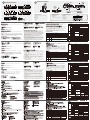
Hardware Overview
B
Hardware Installation
Online Registration
International:
http://support.aten.com
North America:
http://www.aten-usa.com/product_registration
The following contains information that relates to China:
Technical Phone Support
International:
886-2-86926959
North America:
1-888-999-ATEN Ext:4988
United Kingdom:
44-8-4481-58923
Package Contents
1 VE500T / VE500R / VE500RQ A/V Over Cat 5 Extender
1 Power Adapter
1 Rack Mount Kit
1 Terminal Block
1 Grounding Wire
1 User Guide
12 3 4
AUDIO IN RS-232 POWERVGA IN
1 2 3 4
12345
VGA OUTREMOTE I/OAUDIO OUT
L+ L- R+ R-
AUDIO OUT
L+ L- R+ R-
AUDIO IN
1 2 3 4 5
1 2 3 654
Picture Compensation
LINK POWER
1 2 3 4 5 6
A. VE500T Front View
B. VE500T Rear View
C. VE500R Front View
1
1
1234
5
VGA OUTREMOTE I/OAUDIO OUTL+ L- R+ R-
AUDIO OUT
1 2 3 4 5
1 2 3 654
1 2 3 4 5 6
D. VE500RQ Front View
E. VE500R/RQ Rear View
F. All Units Side View
1
11
Local
PC
VGA/Audio
Cable
2
AUDIO IN RS-232 POWERVGA IN
barcode scannertouchscreen
1
2
11
VE500T (Front View) VE500RQ (Front View)
VGA OUTREMOTE I/OAUDIO OUT
L+ L- R+ R-
AUDIO OUT
VGA OUTREMOTE I/OAUDIO OUT
L+ L- R+ R-
AUDIO OUT
L+ L- R+ R-
AUDIO IN
Cat 5e Cable
5
657
89
9710
43
AVR
3
89
45
56 7 7910
VE500T (Rear View)
VE500RQ/R (Rear View)
B. VE500T – visione posteriore
1. Presa d’alimentazione
2. Porte d’entrata/uscita audio bilanciate
3. Porta d’uscita audio stereo (audio out)
4. Porta da dispositivo a dispositivo (I/O remoto)
5. Porta d’uscita video (video out)
VE500T
Alimentazione VERDE Si illumina ad indicare che il dispositivo è alimentato.
VE500R
Alimentazione VERDE Si illumina ad indicare che il dispositivo è alimentato.
Collegamento ARANCIONE
Rimane acceso fisso per indicare che il collegamento con il trasmettitore funziona.
•
Lampeggia per indicare che il collegamento con il trasmettitore presenta dei problemi.
•
Comp. Imm BLU Si illumina per indicare che la Compensazione dell’immagine è attivata.
VE500RQ
B BLU Lampeggia per indicare che il colore Blu è selezionato; utilizzare i pulsanti +/- per la regolazione.
•
G /
Collegamento
VERDE/
ARANCIONE
Rimane acceso fisso ARANCIONE per indicare che il collegamento con il trasmettitore funziona.
•
Lampeggia ARANCIONE per indicare che il collegamento con il trasmettitore presenta dei
•
problemi.
Lampeggia VERDE per indicare che il colore Verde è selezionato; utilizzare i pulsanti +/- per la
•
regolazione.
R /
Alimentazione
ROSSO/
VERDE
Si illumina VERDE ad indicare che il dispositivo è alimentato.
•
Lampeggia ROSSO per indicare che il colore Rosso è selezionato; utilizzare i pulsanti +/- per la
•
regolazione.
Rimane acceso fisso ROSSO (+ il LED G/Collegamento acceso VERDE) per indicare che
•
Compensazione video verrà selezionato per la regolazione.
VE500T
㟁※ 䜾䝸䞊䞁 〇ရ䛾㟁※䛜䜸䞁䛻䛺䛳䛶䛔䜛䛣䛸䜢♧䛧䜎䛩䚹
VE500R
㟁※ 䜾䝸䞊䞁 〇ရ䛾㟁※䛜䜸䞁䛻䛺䛳䛶䛔䜛䛣䛸䜢♧䛧䜎䛩䚹
䝸䞁䜽㻌 䜸䝺䞁䝆
Ⅼⅉ䛧䛶䛔䜛ሙྜ䛿䚸䝖䝷䞁䝇䝭䝑䝍䞊䛸䛾᥋⥆䛜☜❧䛥䜜䛶䛔䜛䛣䛸䜢♧䛧䜎䛩䚹
•
Ⅼ⁛䛧䛶䛔䜛ሙྜ䛿䚸䝖䝷䞁䝇䝭䝑䝍䞊䛸䛾᥋⥆䛻ఱ䛛ၥ㢟䛜䛒䜛䛣䛸䜢♧䛧䜎䛩䚹
•
⏬㉁⿵ṇ
䝤䝹䞊 Ⅼⅉ䛧䛶䛔䜛ሙྜ䛿䚸⏬㉁⿵ṇ୰䛷䛒䜛䛣䛸䜢♧䛧䜎䛩䚹
VE500RQ
㻮㻌 䝤䝹䞊
Ⅼ⁛䛧䛶䛔䜛ሙྜ䛿䚸䝤䝹䞊䛜㑅ᢥ䛥䜜䛶䛔䜛䛣䛸䜢♧䛧䜎䛩䚹䝥䝷䝇㻛䝬䜲䝘䝇䝪䝍䞁䜢⏝䛧
•
䛶ㄪᩚ䛧䛶䛟䛰䛥䛔䚹
㻳㻌㻛㻌
䝸䞁䜽
䜾䝸䞊䞁㻛㻌
䜸䝺䞁䝆
䜸䝺䞁䝆䛻Ⅼⅉ䛧䛶䛔䜛ሙྜ䛿䝖䝷䞁䝇䝭䝑䝍䞊䛸䛾᥋⥆䛜☜❧䛥䜜䛶䛔䜛䛣䛸䜢♧䛧䜎䛩䚹
•
䜸䝺䞁䝆䛻Ⅼ⁛䛧䛶䛔䜛ሙྜ䛿䚸䝖䝷䞁䝇䝭䝑䝍䞊䛸䛾᥋⥆䛻ఱ䛛ၥ㢟䛜䛒䜛䛣䛸䜢♧䛧䜎䛩䚹
•
䜾䝸䞊䞁䛻Ⅼ⁛䛧䛶䛔䜛ሙྜ䛿䚸䜾䝸䞊䞁䛜㑅ᢥ䛥䜜䛶䛔䜛䛣䛸䜢♧䛧䜎䛩䚹䝥䝷䝇㻛䝬䜲䝘䝇䝪䝍
•
䞁䜢⏝䛧䛶ㄪᩚ䛧䛶䛟䛰䛥䛔䚹
㻾㻌㻛㻌
㟁※
䝺䝑䝗㻛㻌
䜸䝺䞁䝆
䜾䝸䞊䞁䛻Ⅼⅉ䛧䛶䛔䜛ሙྜ䛿䚸〇ရ䛾㟁※䛜䜸䞁䛻䛺䛳䛶䛔䜛䛣䛸䜢♧䛧䜎䛩䚹
•
䝺䝑䝗䛻Ⅼ⁛䛧䛶䛔䜛ሙྜ䛿䚸䝺䝑䝗䛜㑅ᢥ䛥䜜䛶䛔䜛䛣䛸䜢♧䛧䜎䛩䚹䝥䝷䝇㻛䝬䜲䝘䝇䝪䝍䞁䜢
•
⏝䛧䛶ㄪᩚ䛧䛶䛟䛰䛥䛔䚹
䝺䝑䝗䛻Ⅼⅉ䛧䚸㻳㻌㻛㻌䝸䞁䜽㻸㻱㻰䛜䜾䝸䞊䞁䛻Ⅼⅉ䛧䛶䛔䜛ሙྜ䛿䚸⏬㉁⿵ṇ୰䛷䛒䜛䛣䛸䜢♧䛧䜎䛩䚹
•
VE500T
႖ဴ ீ຺ ᇣხඓ၉ఈၦ႖ဴၕ෦ધၰఋ௴ઇၕਜ਼൘ሥఁఋ
VE500R
႖ဴ ீ຺ ᇣხඓ၉ఈၦ႖ဴၕ෦ધၰఋ௴ઇၕਜ਼൘ሥఁఋ
ൟሙ ഇხ
ઢᇣႦၰၒඓ႖ૺဉછ࿘ၗၕਜ਼൘ሥఁఋ
•
ଌၦඓ႖ૺဉછබ႞ਜ਼ၰၗၕਜ਼൘ሥఁఋ
•
ጷඓพື ኒೣ຺ ᇣხඓጷඓพືૺၦጺໜጷ࿘ၗၕਜ਼൘ሥఁఋ
VE500RQ
* ኒೣ຺ ଌၦඓኒೣ຺ၦ໓ሳ࿘ၗၕਜ਼൘ሥఁఋዖགྷቾၕຫဧዻ႗ጁఁఋ
•
/ൟሙ
ீ຺
ഇხ຺
ഇხ຺ၒചઢᇣႦၰၒඓ႖ૺဉછ࿘ၗၕਜ਼൘ሥఁఋ
•
ഇხ຺ၒചଌၦඓ႖ૺဉછබ႞ਜ਼ၰၗၕਜ਼൘ሥఁఋ
•
ீ຺ၒചଌၦඓீ຺ၦ໓ሳ࿘ၗၕਜ਼൘ሥఁఋዖགྷቾၕຫဧዻ
•
Ⴎ႗ጁఁఋ
:႖ဴ
຺
ீ຺
ீ຺ၒചᇣხඓ၉ఈၦ႖ဴၕ෦ધၰఋ௴ઇၕਜ਼൘ሥఁఋ
•
຺ၒചଌၦඓ຺ၦ໓ሳ࿘ၗၕਜ਼൘ሥఁఋዖགྷቾၕ
•
ຫဧዻႮ႗ጁఁఋ
຺ၒചઢᇣႦၰၒඓ/4QVS4-,௴ீ຺ၒചᇣႦၰၗ๗ಀพື
•
ૺၦ໓ሳౙઇၭၕਜ਼൘ሥఁఋ
Funzione VE500T VE500R VE500RQ
Connettori
Entrata video (Video
in)
1 maschio HDB-15 (blu) No
Uscita video (Video
out)
1 femmina HDB-15 (blu)
Entrata
audio
Stereo
1 femmina mini stereo
(verde)
No
Bilanciato
1 connettore a vite
impedibile a 5 poli (verde)
Uscita
audio
Stereo 1 femmina mini stereo (verde)
Bilanciato 1 connettore a vite impedibile a 5 poli (verde)
RS-232 1 x DB-9 femmina (nero) 1 x DB-9 maschio (nero)
Da dispositivo a
dispositivo
1 femmina RJ-45
Alimentazione 1 connettore CC (nero)
Interruttori
Compensazione / Su
No
1 pulsante
No
Compensazione / Giù 1 pulsante
Colore / Su
No
1 pulsante
Seleziona / Giù 1 pulsante
LED
Alimentazione 1 (verde) 1 (verde)
No
Collegamento
No
1 (arancione)
Compensazione
dell’immagine
1 (blu)
B
No
1 (blu)
G / Collegamento 1 (verde/arancione)
R / Alimentazione 1 (rosso/verde)
Video No
1920x1200 @60Hz (30 m);
1600x1200 @60Hz (150 m)
1920x1200 @60Hz (150 m);
1280x1024 @60Hz (300 m)
Consumo elettrico CC 5.3V, 2.98W CC 5.3V, 4.04W CC 5.3V, 5.03W
Condizioni
ambientali
Temperatura operativa 0 a 50 °C
Temperatura di
conservazione
-20 a 60 °C
Umidità Da 0 a -80% umidità relativa, senza condensa
Proprietà
fisiche
Case Metallo
Peso 0.48 kg
Dimensioni
(L x P x H))
20.00 x 8.00 x 2.50 cm
ᶵ⬟
VE500T VE500R VE500RQ
䝁䝛䜽䝍䞊
䝡䝕䜸ධຊ
㻰㻙㼟㼡㼎㻝㻡䜸䝇㻔䝤䝹䞊㻕㻌
㽢㻝
㻺㻛㻭
䝡䝕䜸ฟຊ 㻰㻙㼟㼡㼎㻝㻡䝯䝇㻔䝤䝹䞊㻕㽢㻝
䜸䞊䝕䜱
䜸ධຊ
䝇䝔䝺䜸
䝭䝙䝇䝔䝺䜸䝆䝱䝑䜽䝯䝇
䠄䜾䝸䞊䞁䠅㽢㻝
㻺㻛㻭
䝞䝷䞁䝇
䜻䝱䝥䝔䜱䝤䝇䜽䝸䝳䞊㻡
ᴟ䠄䜾䝸䞊䞁䠅㽢㻝
䜸䞊䝕䜱
䜸ฟຊ
䝇䝔䝺䜸 䝭䝙䝇䝔䝺䜸䝆䝱䝑䜽䝯䝇䠄䜾䝸䞊䞁䠅㽢㻝
䝞䝷䞁䝇 䜻䝱䝥䝔䜱䝤䝇䜽䝸䝳䞊㻡ᴟ䠄䜾䝸䞊䞁䠅㽢㻝
㻾㻿㻙㻞㻟㻞㻌 㻰㻮㻙㻥㻌䝯䝇㻌㻔䝤䝷䝑䜽㻕㽢㻝 㻰㻮㻙㻥㻌䜸䝇㻌㻔䝤䝷䝑䜽㻕㽢㻝
䝸䞁䜽 㻾㻶㻙㻠㻡䝯䝇㽢㻝㻌
㟁※ 㻰㻯䝆䝱䝑䜽㻔䝤䝷䝑䜽㻕㽢㻝
䝇䜲䝑䝏
⿵ṇ㻌㻛㻌㼁㼜
㻺㻛㻭
䝥䝑䝅䝳䝪䝍䞁㽢㻝
㻺㻛㻭
⿵ṇ㻌㻛㻌㻰㼛㼣㼚 䝥䝑䝅䝳䝪䝍䞁㽢㻝
䜹䝷䞊㻌㻛㻌㼁㼜
㻺㻛㻭
䝥䝑䝅䝳䝪䝍䞁㽢㻝
㑅ᢥ㻌㻛㻌㻰㼛㼣㼚 䝥䝑䝅䝳䝪䝍䞁㽢㻝
㻸㻱㻰
㟁※ 㻝㻌㻌㻔䜾䝸䞊䞁㻕 㻝㻌㻔䜾䝸䞊䞁㻕
㻺㻛㻭
䝸䞁䜽
㻺㻛㻭
㻝㻌㻔䜸䝺䞁䝆㻕
⏬㉁⿵ṇ 㻝㻌㻔䝤䝹䞊㻕
㻮
㻺㻛㻭
㻝㻌㻔䝤䝹䞊㻕
㻳㻌㻛㻌䝸䞁䜽 㻝㻌㻔䜾䝸䞊䞁㻛䜸䝺䞁䝆㻕
㻾㻌㻛㻌㟁※ 㻝㻌㻔䝺䝑䝗㻛䜾䝸䞊䞁㻕
ゎീᗘ
N/A
1920x1200 @60Hz (30 m);
1600x1200 @60Hz (150 m)
1920x1200 @60Hz (150 m);
1280x1024 @60Hz (300 m)
ᾘ㈝㟁ຊ
DC 5.3V, 2.98W DC 5.3V, 4.04W DC 5.3V, 5.03W
⏝⎔ቃ
ືస ᗘ
0–50°C
ಖ⟶ ᗘ
-20–60°C
‵ᗘ 㻜䇵㻤㻜㻑㻌㻾㻴㻘⤖㟢䛺䛝䛣䛸
ᮏయ
䜿䞊䝇ᮦᩱ 䝯䝍䝹
㔜㔞
0.48 kg
䝃䜲䝈㻔㼃㽢㻰㽢㻴㻕
20.00 x 8.00 x 2.50 cm
ጚត VE500T VE500R VE500RQ
ᇑሽ
๗ಀၮഎ
`0,*5ITM
ኒೣ຺
㻺㻛㻭
๗ಀᆖഎ `0,*.MUITMኒೣ຺
ಀ
ၮഎ
༺ቇഅ
`ුఁ༺ቇഅႂ
.MUITMீ຺
㻺㻛㻭
ෳ༺
`ધႜຫᇑሽ
૰ீ຺
ಀ
ᆖഎ
༺ቇഅ `ුఁ༺ቇഅႂ.MUITMீ຺
ෳ༺ `ધႜຫᇑሽ૰ீ຺
㻾㻿㻙㻞㻟㻞㻌㻌
`,*!.MUITM
અၔ຺
`,*!5ITMઅၔ຺
၉ఈఝ၉ఈછ `:2.MUITM
႖ဴ `,+2IKSઅၔ຺
༺၁ᆳ
พື၁
㻺㻛㻭
`ዖགྷቾ
㻺㻛㻭
พືྤ೭ `ዖགྷቾ
ᇀೡ၁
㻺㻛㻭
`ዖགྷቾ
໓ሳྤ೭ `ዖགྷቾ
㻸㻱㻰
႖ဴ ீ຺ ீ຺
㻺㻛㻭
ൟሙ
㻺㻛㻭
ഇხ຺
ጷඓพື ኒೣ຺
*
㻺㻛㻭
ኒೣ຺
/ൟሙ ீ຺ഇხ຺
:႖ဴ ຺ீ຺
๗ಀ
N/A
1920x1200 @60Hz (30 m);
1600x1200 @60Hz (150 m)
1920x1200 @60Hz (150 m);
1280x1024 @60Hz (300 m)
႖ဴ๗
DC 5.3V, 2.98W DC 5.3V, 4.04W DC 5.3V, 5.03W
ጹઠ
ၵ
0–50°C
พશ
-20–60°C
ཀ ō :06WVKWVLMV[QVO
ဘશ
ႁჲ
ඳ
0.48 kg
ሙૺ4`?`0
20.00 x 8.00 x 2.50 cm
-
 1
1
-
 2
2


dans d''autres langues
- italiano: ATEN VE500T Manuale utente
- English: ATEN VE500T User manual
- español: ATEN VE500T Manual de usuario
- Deutsch: ATEN VE500T Benutzerhandbuch
Documents connexes
-
ATEN VE500R Guide de démarrage rapide
-
ATEN VS0801 Guide de démarrage rapide
-
ATEN VE170 Guide de démarrage rapide
-
-
-
-
-
-
-