TPI CV Series Installation and Operation Instructions
- Taper
- Installation and Operation Instructions

REV. 2/19 ECO 1-7514 1 of 4 FORM 9532
INSTALLATION
INSTRUCTIONS
INSTALLATION AND OPERATION INSTRUCTIONS
CV SERIES COVE HEATER
INSTALLATION INSTRUCTIONS:
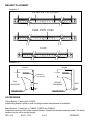
The CV series cove heater is designed for wall or ceiling mount. Maintain at least 2-1/2” from the
ceiling and 3/4” from back of the heater to the wall. See illustration 2. Do not block the heater in any
manner. Maintain at least 6 inches between the heater and draperies.
1. The cove heater is provided with wall mounting brackets. The quantity of brackets is determined by
length. CV45 (2), CV60 thru CV90 (3) and CV100 thru CV125(4). See illustration 1.
2. The brackets should be mounted in a wall stud for secure mounting. Hollow wall anchors in drywall
are not recommended.
3. The CV series is provided with 1/4 inch knockouts along the back for attachment of wall mounting
brackets.
Should a stud be out of alignment with knockouts, a 1/4in. hole can be drilled for placement
of a bracket.
4. Remove the front cover by removing the screws along the bottom.
5. Determine the location of the mounting brackets and remove the corresponding 1/4 in. knockout.
Attach wall mounting bracket with nut and lockwasher. Position the cove heater and secure with the
appropriate hardware for the mounting surface. Alternately, the brackets may be mounted to the wall
and then mount the heater. More than one person may be required for mounting longer length units.
Once the back is secured to the wall, bring power into either end through the provided knockouts.
Note: Supply wire must be 90 deg. C wire. All connections should be made by a licensed electrician.
All wiring shall be in accordance with the N.E.C. or authority having juridiction.
6. Replace the front cover. Note: Do not over tighten the screws. The screws should be tight enough
to secure the cover but also allow expansion and contraction of the front.
7. Make wiring connections. See wiring diagrams for connections.
8. Note: The CV series does not have an intergral thermostat. The CV series must be controlled from
a remote wall thermostat.
OPERATION
1. Turn on the power supply to the heater.
2. Rotate thermostat knob fully clockwise.
3. Allow room to reach desired temperature, then rotate thermostat knob counter-clockwise until the
heater de-energizes. the thermostat will maintain temperature.

REV. 2/19 ECO 1-7514 2 of 4 FORM 9532
IMPORTANT INSTRUCTIONS
When using electrical appliances, basic precautions should always be followed to reduce the risk of re,
electrical shock, and injury to persons, including the following:
1. Read all instructions before using this heater.
2. CAUTION:
High temperatures. Keep cords and all other combustible material, such as
furniture,
papers, clothes and curtains away from the heater. For safe and efcient operation,
keep an
open space around heater of three feet in front and 12 inches at ends and rear.
ATTENTION:
Les températures élevées. Gardez les cordons et tout autre matériau combustible,
tels que les meubles, papiers, vêtements et rideaux à l'extérieur de l'appareil de chauffage.
Pour
un fonctionnement sûr et efcace, garder un espace ouvert autour de chauffage
de trois pieds à
l'avant et 12 pouces aux extrémités et à l'arrière.
3. Extreme caution is necessary when any heater is used by or near children or invalids and whenever
the heater is left operating and unattended.
4. Do not operate any heater after it malfunctions, has been dropped or damaged in any manner.
Return heater to authorized service facility for examination, electrical or mechanical adjustment, or
repair.
5. Do not use outdoors.
6. To disconnect heater, turn controls to off, and turn off power to heater circuit at main disconnect
panel (or operate internal disconnect switch if provided)
.
7. Do not insert or allow foreign objects to enter any ventilation or exhaust opening as this may cause
an electric shock or re, or damage the heater.
8. To prevent a possible re, do not block air intakes or exhaust in any manner.
9. A heater has hot and arcing or sparking parts inside. WARNING: Do not use it in area where gasoline,
paint, or ammable liquids are used or stored.
10. Use this heater only as described in this manual. Any other use not recommended by the manufacturer
may cause re, electric shock, or injury to persons.
11. This heater may or may not include an audible or visual alarm to warn that parts of the heater are
getting excessively hot. If the alarm sounds (or illuminates), immediately turn the heater off and
inspect for any objects on or adjacent to the heater that may have blocked the airow or otherwise
caused high temperatures to have occured.
DO NOT OPERATE THE HEATER WITH THE ALARM SOUNDING (OR ILLUMINATING).
12. SAVE THESE INSTRUCTIONS

REV. 2/19 ECO 1-7514 3 of 4 FORM 9532
CEILING
2-1/2" MIN.
WALL
MOUNTING
CEILING
MOUNTING
WALL
3
4
"
6 FEET MIN. ABOVE
FINISHED FLOOR
BREAK OFF
TOP SECTION
MOUNTING
BRACKET
CEILING
2-1/2" MIN.
WALL
3
4
"
6 FEET MIN. ABOVE
FINISHED FLOOR
MOUNTING
BRACKET
BRACKET PLACEMENT
Illustration 1
ACCESSORIES
Ceiling Bracket - Catalog NO. CVCBX.
Install ceiling bracket similar to wall mounting brackets as explained in installation.
Blank Sections - Catalog No.’s CVB42X, CVB60X and CVB84X.
Install blank sections to ll space between heaters. Install blank sections same as heater. The blank
sections may be cut to desired length.
Illustration 2
CV45
CV60, CV75, CV90
CV100, CV110, CV125,

REV. 2/19 ECO 1-7514 4 of 4 FORM 9532
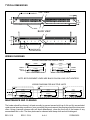
TYPICAL DIMENSIONS
WIRING DIAGRAMS
MAINTENANCE AND CLEANING
The heater should be cleaned at least annually to prevent excess build-up of dirt and lint accumulated
under normal operating conditions. In an unusually dirty environment the cleaning should be done more
often. Using a vacuum cleaner with soft brush attachment, clean the the front of the heater of any
accumulated dirt or lint. The face plate can be cleaned with damp cloth and mild detergent.
WALL
2 1/4"
1-7/16"
7
8
" K.O FOR
1
2
" CONDUIT
TOP VIEW
BACK VIEW
2.0"
1
4
" KNOCKOUTS
FOR MOUNTING
TYPICAL
3-1/4"
4-1/4"
WIRING DIAGRAM FOR MULTIPLE UNITS
ELEMENT
BLACK
WHITEWHITE
WHITE
GND
POWER
SUPPLY
ELEMENT
BLACK
WHITEWHITE
WHITE
ELEMENT
BLACK
WHITEWHITE
WHITE
GND
GND
ELEMENT
BLACK
WHITEWHITE
WHITE
GND GND
LEFT HAND CONNECTION
POWER
SUPPLY
ELEMENT
BLACK
WHITEWHITE
WHITE
GND GND
RIGHT HAND CONNECTION
POWER
SUPPLY
WIRING DIAGRAM FOR SINGLE UNITS
NOTE: BOTH ELEMENT LEADS ARE BLACK ON 208 & 240 VOLT HEATERS.
-
 1
1
-
 2
2
-
 3
3
-
 4
4


TPI CV Series Installation and Operation Instructions
- Taper
- Installation and Operation Instructions
dans d''autres langues
- English: TPI CV Series