Rointe Elba Pro Le manuel du propriétaire
- Taper
- Le manuel du propriétaire

Elba electric pro
Models / Modelos / Modèle / Modellen
PRO 400 | 450 | 500 | 550
MANUAL DE INSTALACIÓN Y USO
Página 14
MANUAL DE INSTALAÇÃO E UTILIZAÇÃO
Página 26
ES
PT
INSTRUCTIONS & INSTALLATION GUIDE
Page 02
EN
INSTALLATIE- EN GEBRUIKERSHANDLEIDING
Bladzijde 50
NL
MANUEL D’INSTALLATION ET D’UTILISATION
Page 38
FR

2
Installation & safety precautions (EN 60335 Standards)
Before switching on the product, please read the “Installation & Safety Precautions” in detail rst to
ensure the correct operation of the product.
Installation precautions
The product is designed for household or residential use. You are advised to have the product installed
by an authorized professional installer. Make sure the product is properly connected to 230V.
ATTENTION
Children under 3 years of age should be kept out of reach of the appliance
unless continuously supervised. Children from the age of 3 years to 8
years should only switch the appliance on/off when it has been placed
or installed in its normal intended use position and when they have been
given supervision or instruction concerning use of the appliance in a safe
way and understand the hazards involved. Children from 3 years of age to
8 years of age should not plug in, adjust or clean the appliance or carry out
maintenance operations.
This appliance can be used by children aged from 8 years and above
and persons with reduced physical sensory or mental capabilities or lack
of experience and knowledge if they are supervised or have been given
instruction concerning use of the appliance in a safe way and understand
the hazards involved. Children should not play with the appliance. Cleaning
and user maintenance should not be carried out by children without
supervision. Children must be supervised at all times to ensure that they
do not interfere with the product.
This product is lled with a precise amount of special oil that does not
need any maintenance. Any repairs requiring the opening of the oil tank
must only be done by an ofcial Rointe installer or its after-sales service
personnel, who should also be notied should an oil leak be noticed. The
regulations on discarding oil when the heater is being disposed of must be
observed.
Do not cut the power supply cable under any circumstances in order to
avoid electrical risks and to guarantee the correct operation of the towel
rail.
Do not switch on the product if you notice any external damage when
unpacking or installing the towel rail. If the power cable is damaged, it
must be replaced by the manufacturer, its after-sales service or authorized
personnel in order to avoid any damage.

3
ELBA PRO
EN
Do not spray or wet the product. During operation, keep the product
away from combustible materials such as curtains, furniture, etc. Do not
place anything other than clothes, towels or non-ammable fabrics on the
product.
The towel rail must be installed in such a way that the power plug is always
accessible. The power cable must never be in contact with the product
during operation.
CAUTION - Never touch the product with wet hands or any wet
body parts.
CAUTION - Some parts of this product may become very hot
and cause burns. Particular care should be taken when children
and vulnerable persons are present.
Contents
1. Technical Specications ..........................................................................................................................4
2. Product Installation........ .........................................................................................................................8
2.1. Mounting ..........................................................................................................................................8
2.2. Connecting instructions .................................................................................................................9
2.3. Specic regulations for bathrooms...............................................................................................9
3. Switch on & off (stand-by) .......................................................................................................................10
4. Maintenance & Cleaning............... .................................................................................................,........10
5. Guarantee......................................... ........................................................................................................10
6. How to register your guarantee....... .......................................................................................................12

4
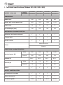
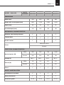
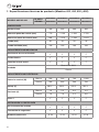
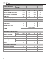
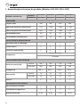
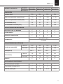
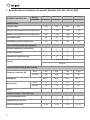
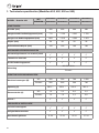
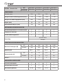
1. Technical specifications (Models 400, 450, 500 & 550)
MODEL - Width 400
WHITE
TELO*40B077 TELO*40B112 TELO*40B150 TELO*40B172
CHROME
TELO*40C077 TELO*40C112 TELO*40C150 TELO*40C172
DIMENSIONS
Width (mm) 400 400 400 400
Height with control panel (mm) 863 1,213 1,593 1,813
Depth (mm) 50 50 50 50
Installed depth (mm) 100 100 100 100
MECHANICAL CHARACTERISTICS
Stainless steel heating element
Thermal fluid
On/Off control
Finish
White RAL 9016
Chrome
ELECTRICAL CHARACTERISTICS
Nominal power (W)
White 300 500 700 1,000
Chrome 300 300 500 700
Voltage (V) 230 V ~ 230 V ~ 230 V ~ 230 V ~
Current (A)
White 1.3 2.2 3.3 4.4
Chrome 1.3 1.3 2.2 3.3
Class I
SAFETY & INSTALLATION
Installation kit included
Safety thermostat
Protection grade IP 54 IP 54 IP 54 IP 54

5
ELBA PRO
EN
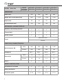
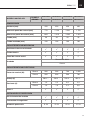
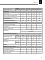
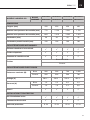
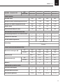
MODEL - Width 450
WHITE
TELO*45B077 TELO*45B112 TELO*45B150 TELO*45B172
CHROME
TELO*45C077 TELO*45C112 TELO*45C150 TELO*45C172
DIMENSIONS
Width (mm) 450 450 450 450
Height with control panel (mm) 863 1,213 1,593 1,813
Depth (mm) 50 50 50 50
Installed depth (mm) 100 100 100 100
MECHANICAL CHARACTERISTICS
Stainless steel heating element
Thermal fluid
On/Off control
Finish
White RAL 9016
Chrome
ELECTRICAL CHARACTERISTICS
Nominal power (W)
White 300 500 700 1,000
Chrome 300 300 500 700
Voltage (V) 230 V ~ 230 V ~ 230 V ~ 230 V ~
Current (A)
White 1.3 2.2 3.3 4.4
Chrome 1.3 1.3 2.2 3.3
Class I
SAFETY & INSTALLATION
Installation kit included
Safety thermostat
Protection grade IP 54 IP 54 IP 54 IP 54

6
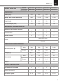
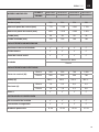
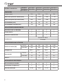
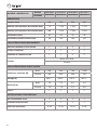
MODEL - Width 500
WHITE
TELO*50B077 TELO*50B112 TELO*50B150 TELO*50B172
CHROME
TELO*50C077 TELO*50C112 TELO*50C150 TELO*50C172
DIMENSIONS
Width (mm) 500 500 500 500
Height with control panel (mm) 863 1,213 1,593 1,813
Depth (mm) 50 50 50 50
Installed depth (mm) 100 100 100 100
MECHANICAL CHARACTERISTICS
Stainless steel heating element
Thermal fluid
On/Off control
Finish
White RAL 9016
Chrome
ELECTRICAL CHARACTERISTICS
Nominal power (W)
White 300 500 700 1,000
Chrome 300 300 500 700
Voltage (V) 230 V ~ 230 V ~ 230 V ~ 230 V ~
Current (A)
White 1.3 2.2 3.3 4.4
Chrome 1.3 1.3 2.2 3.3
Class I
SAFETY & INSTALLATION
Installation kit included
Safety thermostat
Protection grade IP 54 IP 54 IP 54 IP 54

7
ELBA PRO
EN
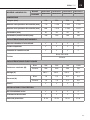
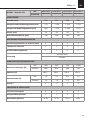
MODEL - Width 550
WHITE
TELO*55B077 TELO*55B112 TELO*55B155 TELO*55B172
CHROME
TELO*55C077 TELO*55C112 TELO*55C155 TELO*55C172
DIMENSIONS
Width (mm) 550 550 550 550
Height with control panel (mm) 863 1,213 1,593 1,813
Depth (mm) 50 50 50 50
Installed depth (mm) 100 100 100 100
MECHANICAL CHARACTERISTICS
Stainless steel heating element
Thermal fluid
On/Off control
Finish
White RAL 9016
Chrome
ELECTRICAL CHARACTERISTICS
Nominal power (W)
White 300 500 700 1,000
Chrome 300 300 500 700
Voltage (V) 230 V ~ 230 V ~ 230 V ~ 230 V ~
Current (A)
White 1.3 2.2 3.3 4.4
Chrome 1.3 1.3 2.2 3.3
Class I
SAFETY & INSTALLATION
Installation kit included
Safety thermostat
Protection grade IP 54 IP 54 IP 54 IP 54

8
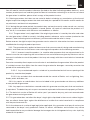
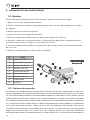
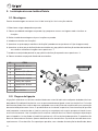
2. Product installation
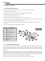
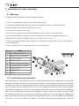
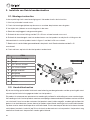
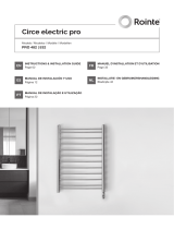
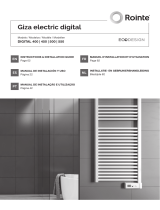
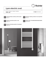
2.1. Mounting instructions
Inside the packaging you will nd a xing kit. Please nd the instructions below:
1. Choose the right part of the wall.
2. Place the mounting stencil on the wall, marking the places for the holes.
3. Remove the stencil and make the holes in the wall.
4. Insert the rawl plugs in the holes made.
5. Screw the plastic fastener to the wall with the 5.5 x 50 mm screw.
6. Screw the two brackets for supporting the product and the plastic fastener to the horizontal tube
of the product like in Figure 1 with the 8 x 26 mm screw.
7. Insert what you have assembled in Section 6 into the plastic piece and x well with the 5 x 12
mm screw.
8. Place the cover on the piece supporting the product.
NO. ELEMENT
1 10 x 40 mm Rawl Plug
2 Bracket
3 5.5 x 50 mm Screw
4 5 x 12 mm Screw
5 Bracket Insert
6 Bracket Head
7 8 x 26 mm Screw
8 Cap
9 Product
2.2. Connecting instructions
Connection to the mains must be made observing the voltage stated on the product technical data label.
This product is designed to be permanently installed connected to xed facilities. The product power
supply circuit must have an all-pole circuit breaker switch with a separation of at least 3 mm between
the contacts.
The product must be installed, if possible, away from any source of draughts (windows, doors) or any
other thing which may affect its functioning. In this way, the temperature will not be affected. Place any
object which might prevent the air ow (furniture, armchairs) 50 cm away from the front of the product.
The product must never be installed immediately below a power point.
The lower part of the control panel must be placed at least 15 cm from the oor.
1
5

9
ELBA PRO
EN
For any product, if the power cable is damaged, it must be replaced by a specic cable. The replacement
of the cable must be done by the maker, its after-sales service or qualied personnel. The technical
specications of your product appear on the technical data label.
OK
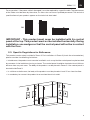
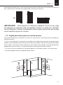
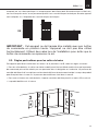
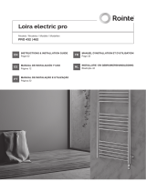
IMPORTANT - This product must never be installed with its control
panel at the top. This product must not be installed horizontally. During
installation, use wedges so that the control panel will not be in contact
with the floor.
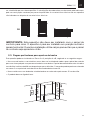
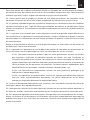
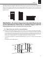
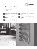
2.3. Specific Regulations for Bathrooms
This product can be safety installed in Zones 3. For installations in Zones 2 (check the scheme below),
please consider the following limitations:
•
In bathrooms, the product must never be installed in such a way that the control panel may be touched
by someone in the bathtub or having a shower. The control panel should be located at least 600 mm
distance from any wet areas. The body of the product can be placed in Zones 2 if the control panel is
located inside Zone 3.
• In a kitchen or bathroom, the body of the product must be placed at least 25 cm from the oor.
• Is mandatory to connect the product to an earthed electrical outlet.

10
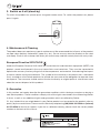
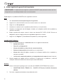
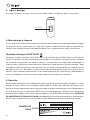
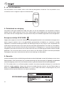
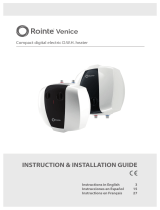
3. Switch on & off (stand-by)
To switch the product on, please press the green button once. To switch the product off, please
press it again.
ON/OFF button
4. Maintenance & Cleaning
The product does not require any type of maintenance. We recommend that all parts of the product
are kept clean (behind, underneath, upper ns, etc.). Do not use any abrasive product on the steel
main body. Clean it with a damp cloth and a pH neutral soap, and the control panel with a dry cloth.
European Directive 2012/19/UE
Under the European Directive 2012/19/UE on waste electrical and electronic equipment (WEEE), the
product cannot be disposed in the usual council bins and containers. They must be separated to
optimize the recovery and recycling of all of the components and materials and reducing the impact
to human health and the environment. The symbol of the container crossed out over a horizontal
line is marked on all of Rointe products to remind the consumer of the obligation to separate them
on disposal. The consumer should contact the local authority or original point of sale to learn more
about the correct disposal of this product.
5. Guarantee
In this section, we hereby describe the guarantee conditions which the buyer acquires on buying a
new Rointe product. These conditions comply with all the rights construed in the national legislation
in force, as well as any additional rights and guarantees which are offered by Rointe.
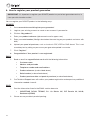
5.1. Any incident that you might detect in your Rointe product can be sorted by the product seller or
quickly by the manufacturer. Please contact Rointe by telephoning (UK) 0203 321 5929 or (Ireland)
01 553 0523 for technical support. If you live in a different country, please check the correct phone
number on the back of this manual.
ELBA PRO
TELON45B077
300 W

11
ELBA PRO
EN
You will need to state the product reference (located on the label indicating product features), serial
number, proof of purchase and the type of incident at hand when contacting us so that we can check
the guarantee. In addition, please attach a copy of the product invoice.
5.2. Rointe guarantees that there are no material defects of design or manufacture at the time of
original acquisition and guarantees the steel main body for a period of 120 months and 24 months for
any electronic and electrical components.
5.3. If during the guarantee period, the product does not work correctly under normal use, and any
design, material or manufacturing defect is found, Rointe will repair or substitute the product as it
may see t, in accordance with the terms and conditions as follows:
5.3.1. The guarantee is only applicable if the original guarantee is issued by the seller and when
the said guarantee is lled in correctly including product reference, series number (marked on the
product’s label indicating technical features), purchase date and the seller’s stamp.
Rointe reserves the right to reject the guarantee service when this information has been removed or
modied after the original product purchase.
5.3.2. The guarantee only applies to those cases that concern material, design and manufacturing
defects, and under no circumstances covers damage to the product for the following reasons:
5.3.2.1 Incorrect use of the product, i.e. used for other purposes that are not construed as its
normal use or for not respecting the instructions of use and maintenance given by Rointe as well as
incorrect installation or use of the product that may not comply with the current technical standards
of safety.
Corrosion caused by direct exposure to salt water is excluded from the guarantee. When the product
is installed no more than 200m from the coast the guarantee for damages caused by corrosion the
period will be reduced by 50%.
5.3.2.2 Any unauthorized repairs carried out by unauthorized technicians or opening of the
product by unauthorized people.
5.3.2.3 Any accidents that are deemed outside the control of Rointe, such as lightning, res,
oods, public disorders, etc.
5.3.3. Any repairs or substitutions that are included in this guarantee do not allow any additions
or new periods of guarantee.
5.3.4. Any repairs or substitutions covered under this guarantee must be parts that are functional-
ly equivalent. The defective parts or parts removed or replaced shall become the property of Rointe.
5.4. The technical service of Rointe will advise you if you need to buy any parts not covered under
the guarantee or out of guarantee.
5.5. This guarantee does not affect the buyer’s legal rights stipulated in the current national legisla-
tion, nor affects those rights against the distributor or installer that could come forth in compliance
with the purchase contract.
5.6. In the absence of a national legal legislation applicable, this guarantee shall prevail and may be
construed as the buyer’s only protection. Rointe, its ofces, distributors and installers may not be
held responsible for any accidental damage that emerges due to infringement of any rules implicitly
related to this product.

12
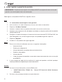
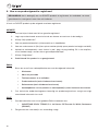
6. How to register your product guarantee
IMPORTANT: It’s important to register your ROINTE product as part of our guarantee service, in
case you wish to make a claim.
You can register your ROINTE product in the following ways:
WEBSITE
1. Go to www.rointe.com/uk/register-your-guarantee/.
2. Login to your existing account or create a new account if you need to.
3. Click on “My products”.
4. Enter your product reference (alphanumeric and in upper case).
5. Enter your serial number (26 digits located on the metal tag on your product and starts with
843).
6. Upload your proof of purchase, such as invoice in PDF, JPEG or PNG format. This is not
mandatory but by doing so you ensure your guarantee period is accurate.
7. Click “Register”.
8. Congratulations! Your product is now registered.
EMAIL
1. Send an email to [email protected] with the following information:
• Customer name
• Address and postcode
• Telephone number and email address
• Product reference (as described above)
• Serial number (as described above)
• Product purchase date and proof of purchase (as described above).
2. Our Technical Support team will conrm your product registration and request any additional
information needed via email.
POST
1. Post the information listed in the EMAIL section above to:
• INDUSTRIAS ROYAL TERMIC, S.L. t/a Rointe UK, C/E Parcela 43, 30140,
Santomera (SPAIN)
2. Please ensure you obtain proof of posting.

13
ELBA PRO
EN

14
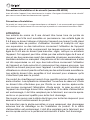
Precauciones de instalación y de seguridad (EN 60335 Standards)
Antes de encender el producto léase el apartado de “precauciones de instalación y de seguridad”
detenidamente para asegurar el funcionamiento correcto del producto.
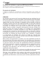
Precauciones de instalación
Este producto está diseñado para uso doméstico o residencial. Se recomienda que el producto sea
instalado por un profesional autorizado. Asegúrese de que el producto esté conectado correctamente
a 230V.
ATENCIÓN
Los niños menores de 3 años deben mantenerse fuera del alcance del
aparato a menos que estén continuamente supervisados. Los niños de 3 a
8 años sólo deben encender y apagar el aparato cuando se haya colocado
o instalado en su posición normal de uso y cuando se les haya supervisado
o instruido sobre el uso del aparato de forma segura y comprendan
los peligros que conlleva. Los niños de 3 a 8 años no deben enchufar,
ajustar o limpiar el aparato ni realizar operaciones de mantenimiento. Este
aparato puede ser utilizado por niños a partir de 8 años y por personas
con capacidades físicas, sensoriales o mentales reducidas o con falta de
experiencia y conocimientos, siempre que estén supervisados o hayan
recibido instrucciones sobre el uso del aparato de forma segura y entiendan
los peligros que conlleva. Los niños no deben jugar con el aparato. La
limpieza y el mantenimiento del usuario no deben ser realizados por los
niños sin supervisión. Los niños deben ser supervisados en todo momento
para asegurarse de que no intereren con el producto.
Este producto de calefacción se rellena con una cantidad precisa de aceite
especial que no necesita mantenimiento. Las reparaciones que necesitan
la apertura del depósito de uido térmico no deberán efectuarse más que
por Rointe o su servicio posventa. Las reglamentaciones concernientes
a la eliminación de este uido después de que el aparato calefactor sea
desechado deben ser respetadas. Si el cable de alimentación está dañado,
debe ser reemplazado por el fabricante, su servicio posventa o personal
cualicado para evitar daños.
No corte el cable de alimentación bajo ningún concepto con el n de evitar
riesgos eléctricos y garantizar el correcto funcionamiento del producto.
No encienda el secatoallas si observa algún daño externo al desembalar
o instalar el producto. Si el cable de alimentación está dañado, debe ser
sustituido por el fabricante, su servicio postventa o personal autorizado
para evitar cualquier daño.

15
ELBA PRO
ES
No rocíe ni moje el producto. Durante el funcionamiento, mantenga el
producto alejado de materiales combustibles como cortinas, muebles,
etc. No coloque sobre el producto nada que no sea ropa, toallas o tejidos
no inamables.
El secatoallas debe instalarse de forma que el enchufe esté siempre
accesible. El cable de alimentación nunca debe estar en contacto con el
producto durante su funcionamiento.
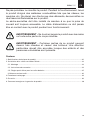
PRECAUCIÓN - No toque nunca el producto con las manos u
otra parte del cuerpo mojadas.
PRECAUCIÓN - Algunas partes de este producto podrían
ponerse muy calientes y causar quemaduras. Se debe prestar
atención especial cuando niños y personas vulnerables estén
presentes.
Contenido
1. Especicaciones técnicas de producto.................................................................................................16
2. Instalación del secatoallas Rointe ..........................................................................................................20
2.1. Montaje ...............................................................................................................................................20
2.2. Normas de conexión..............................................................................................................................20
2.3. Reglas particulares para los cuartos de baño..................................................................................21
3. Encender y apagar..................................................................................................................................22
4. Mantenimiento y limpieza........... ............................................................................................................22
5. Garantía............................................. ......................................................................................................22
6. Como registrar la garantía del producto.............................................. .................................................24

16
1. Especificaciones técnicas de producto (Modelos 400, 450, 500 y 550)
MODELO ANCHO 400
BLANCO
TELO*40B077 TELO*40B112 TELO*40B150 TELO*40B172
CROMO
TELO*40C077 TELO*40C112 TELO*40C150 TELO*40C172
DIMENSIONES
Anchura (mm) 400 400 400 400
Altura sin panel de control (mm) 770 1.120 1.500 1.720
Altura con panel de control (mm) 863 1.213 1.593 1.813
Fondo (mm) 50 50 50 50
Fondo instalado (mm) 100 100 100 100
CARACTERÍSTICAS MECÁNICAS
Resistencia de acero blindado
Fluido térmico
Panel de control on/off
Acabado
Blanco RAL 9016
Cromo
CARACTERÍSTICAS ELÉCTRICAS
Potencia nominal (W)
Blanco 300 500 700 1.000
Cromo 300 300 500 700
Voltaje (V) 230 V ~ 230 V ~ 230 V ~ 230 V ~
Corriente (A)
Blanco 1,3 2,2 3,0 4,4
Cromo 1,3 1,3 2,2 3,0
Clase I
INSTALACIÓN Y PROTECCIÓN
Kit de instalación incluido
Termostato de seguridad
Grado de protección IP 54 IP 54 IP 54 IP 54

17
ELBA PRO
ES
MODELO ANCHO 450
BLANCO
TELO*45B077 TELO*45B112 TELO*45B150 TELO*45B172
CROMO
TELO*45C077 TELO*45C112 TELO*45C150 TELO*45C172
DIMENSIONES
Anchura (mm) 450 450 450 450
Altura sin panel de control (mm) 770 1.120 1.500 1.720
Altura con panel de control (mm) 863 1.213 1.593 1.813
Fondo (mm) 50 50 50 50
Fondo instalado (mm) 100 100 100 100
CARACTERÍSTICAS MECÁNICAS
Resistencia de acero blindado
Fluido térmico
Panel de control on/off
Acabado
Blanco RAL 9016
Cromo
CARACTERÍSTICAS ELÉCTRICAS
Potencia nominal (W)
Blanco 300 500 700 1.000
Cromo 300 300 500 700
Voltaje (V) 230 V ~ 230 V ~ 230 V ~ 230 V ~
Corriente (A)
Blanco 1,3 2,2 3,0 4,4
Cromo 1,3 1,3 2,2 3,0
Clase I
INSTALACIÓN Y PROTECCIÓN
Kit de instalación incluido
Termostato de seguridad
Grado de protección IP 54 IP 54 IP 54 IP 54

18
MODELO ANCHO 500
BLANCO
TELO*50B077 TELO*50B112 TELO*50B150 TELO*50B172
CROMO
TELO*50C077 TELO*50C112 TELO*50C150 TELO*50C172
DIMENSIONES
Anchura (mm) 500 500 500 500
Altura sin panel de control (mm) 770 1.120 1.500 1.720
Altura con panel de control (mm) 863 1.213 1.593 1.813
Fondo (mm) 50 50 50 50
Fondo instalado (mm) 100 100 100 100
CARACTERÍSTICAS MECÁNICAS
Resistencia de acero blindado
Fluido térmico
Panel de control on/off
Acabado
Blanco RAL 9016
Cromo
CARACTERÍSTICAS ELÉCTRICAS
Potencia nominal (W)
Blanco 300 500 700 1.000
Cromo 300 300 500 700
Voltaje (V) 230 V ~ 230 V ~ 230 V ~ 230 V ~
Corriente (A)
Blanco 1,3 2,2 3,0 4,4
Cromo 1,3 1,3 2,2 3,0
Clase I
INSTALACIÓN Y PROTECCIÓN
Kit de instalación incluido
Termostato de seguridad
Grado de protección IP 54 IP 54 IP 54 IP 54

19
ELBA PRO
ES
MODELO ANCHO 550
BLANCO
TELO*55B077 TELO*55B112 TELO*55B150 TELO*55B172
CROMO
TELO*55C077 TELO*55C112 TELO*55C150 TELO*55C172
DIMENSIONES
Anchura (mm) 550 550 550 550
Altura sin panel de control (mm) 770 1.120 1.500 1.720
Altura con panel de control (mm) 863 1.213 1.593 1.813
Fondo (mm) 50 50 50 50
Fondo instalado (mm) 100 100 100 100
CARACTERÍSTICAS MECÁNICAS
Resistencia de acero blindado
Fluido térmico
Panel de control on/off
Acabado
Blanco RAL 9016
Cromo
CARACTERÍSTICAS ELÉCTRICAS
Potencia nominal (W)
Blanco 300 500 700 1.000
Cromo 300 300 500 700
Voltaje (V) 230 V ~ 230 V ~ 230 V ~ 230 V ~
Corriente (A)
Blanco 1,3 2,2 3,0 4,4
Cromo 1,3 1,3 2,2 3,0
Clase I
INSTALACIÓN Y PROTECCIÓN
Kit de instalación incluido
Termostato de seguridad
Grado de protección IP 54 IP 54 IP 54 IP 54

20
2. Instalación del secatoallas Rointe
2.1. Montaje
Dentro del embalaje encontrará un kit de instalación. Véase las instrucciones abajo:
1. Seleccionar el lugar adecuado de la pared.
2. Colocar la plantilla en la pared, haciendo pequeñas marcas en los lugares donde van situados
los agujeros.
3. Retirar la plantilla y hacer los agujeros.
4. Insertar los tacos en los agujeros realizados
5. Atornillar la pieza plástica de anclaje a la pared con el tornillo 6.5 x 50 mm.
6. Atornillar las dos piezas sujeta-secatoallas y la pieza plástica de jación al tubo horizontal del
secatoallas como se ve en la Figura 1 con el tornillo 8 x 26 mm.
7. Insertar el conjunto del punto 6 en la pieza plástica de anclaje y sujetar con el tornillo prisionero
de 5 x 12 mm.
8. Colocar el embellecedor en la pieza sujeta-secatoallas.
Nº. ITEM
1 10 x 40 mm taco
2 Pieza metálica anclaje
3 Tornillo 5.5 x 50 mm
4 Tornillo 5 x 12 mm
5 Inserción de tornillo
6 Cabeza de soporte
7 Tornillo 8 x 26 mm
8 Embellecedor
9 Producto
2.2. Normas de conexión
La conexión a la red debe efectuarse respetando la tensión indicada en la etiqueta de características
técnicas del producto. Este aparato está destinado a ser permanentemente conectado a una instalación
ja. El circuito de alimentación del secatoallas debe incorporar un interruptor de corte unipolar con una
separación de contactos de al menos 3 mm. El aparato debe ser instalado, si es posible al abrigo de
las corrientes de aire (ventanas, puertas) o de cualquier otra cosa que pudiera perturbar su regulación.
Así, le aportará el mejor confort térmico. Coloque todo objeto que pueda suponer un impedimento
a la circulación del aire (muebles, sillones) a 50 cm de la cara delantera del aparato. El aparato no
se deberá colocar delante o justo debajo de un enchufe jo. La parte baja de la caja de mandos
debe situarse como mínimo a 15 cm del suelo. Para cualquier aparato, si el cable de alimentación
está deteriorado, debe ser reemplazado por un cable especíco. La sustitución del cable debe ser
1
5
La page est en cours de chargement...
La page est en cours de chargement...
La page est en cours de chargement...
La page est en cours de chargement...
La page est en cours de chargement...
La page est en cours de chargement...
La page est en cours de chargement...
La page est en cours de chargement...
La page est en cours de chargement...
La page est en cours de chargement...
La page est en cours de chargement...
La page est en cours de chargement...
La page est en cours de chargement...
La page est en cours de chargement...
La page est en cours de chargement...
La page est en cours de chargement...
La page est en cours de chargement...
La page est en cours de chargement...
La page est en cours de chargement...
La page est en cours de chargement...
La page est en cours de chargement...
La page est en cours de chargement...
La page est en cours de chargement...
La page est en cours de chargement...
La page est en cours de chargement...
La page est en cours de chargement...
La page est en cours de chargement...
La page est en cours de chargement...
La page est en cours de chargement...
La page est en cours de chargement...
La page est en cours de chargement...
La page est en cours de chargement...
La page est en cours de chargement...
La page est en cours de chargement...
La page est en cours de chargement...
La page est en cours de chargement...
La page est en cours de chargement...
La page est en cours de chargement...
La page est en cours de chargement...
La page est en cours de chargement...
La page est en cours de chargement...
La page est en cours de chargement...
La page est en cours de chargement...
La page est en cours de chargement...
-
 1
1
-
 2
2
-
 3
3
-
 4
4
-
 5
5
-
 6
6
-
 7
7
-
 8
8
-
 9
9
-
 10
10
-
 11
11
-
 12
12
-
 13
13
-
 14
14
-
 15
15
-
 16
16
-
 17
17
-
 18
18
-
 19
19
-
 20
20
-
 21
21
-
 22
22
-
 23
23
-
 24
24
-
 25
25
-
 26
26
-
 27
27
-
 28
28
-
 29
29
-
 30
30
-
 31
31
-
 32
32
-
 33
33
-
 34
34
-
 35
35
-
 36
36
-
 37
37
-
 38
38
-
 39
39
-
 40
40
-
 41
41
-
 42
42
-
 43
43
-
 44
44
-
 45
45
-
 46
46
-
 47
47
-
 48
48
-
 49
49
-
 50
50
-
 51
51
-
 52
52
-
 53
53
-
 54
54
-
 55
55
-
 56
56
-
 57
57
-
 58
58
-
 59
59
-
 60
60
-
 61
61
-
 62
62
-
 63
63
-
 64
64


Rointe Elba Pro Le manuel du propriétaire
- Taper
- Le manuel du propriétaire
dans d''autres langues
- English: Rointe Elba Pro Owner's manual
- español: Rointe Elba Pro El manual del propietario
- Nederlands: Rointe Elba Pro de handleiding
- português: Rointe Elba Pro Manual do proprietário
Documents connexes
-
 Rointe Lyon PRO Le manuel du propriétaire
-
 Rointe Elba Digital Le manuel du propriétaire
-
 Rointe Circe PRO Le manuel du propriétaire
-
 Rointe Tovare PRO Le manuel du propriétaire
-
 Rointe Elba Oval Le manuel du propriétaire
-
 Rointe Giza Digital Le manuel du propriétaire
-
 Rointe Loira PRO Le manuel du propriétaire
-
 Rointe VENICE Le manuel du propriétaire
-
 Rointe Giza Oval Le manuel du propriétaire
-
 Rointe Lyon OVAL Le manuel du propriétaire


