La page est en cours de chargement...

Compact digital electric D.W.H. heater
INSTRUCTION & INSTALLATION GUIDE
Instructions in English
Instrucciones en Español
Instructions en Français
3
15
27
Venice

2

3
Compact digital electric D.W.H. heater
Venice
Contents
1.
General...........................................................................................................................................................................................4
2.
Important rules............................................................................................................................................................................4
3.
Description and information....................................................................................................................................................4
4.
Installation....................................................................................................................................................................................5
5.
Operation......................................................................................................................................................................................8
6.
Protection against magnesium anode oxidation..................................................................................................................9
7.
Periodic maintenance ................................................................................................................................................................9
8.
Rointe Product Guarantee.......................................................................................................................................................10
9.
European Directive....................................................................................................................................................................11
10.
Dimensions & Technical Characteristics...............................................................................................................................12
11.
Certicate of Guarantee...........................................................................................................................................................13
IMPORTANT
Please read this Instruction Manual carefully to ensure correct operation. It is important that the
installer reads and understands these instructions and unpacks and familiarises themselves with
the equipment before commencing the installation. Please leave this manual with the product after
installation. Failure to observe these installation instructions could render the guarantee null and
void.
PLEASE NOTE
Thank you for choosing the VENICE D.H.W. compact heater. Manufactured with the highest quality
components, the VENICE Compact was designed for you.
The VENICE Compact domestic hot water heater has passed the most stringent quality controls to
meet the highest safety requirements. Before starting to use the VENICE Compact hot water heater,
we recommend that you read this manual carefully. Failure to observe these installation instructions
could cancel the guarantee and render it invalid.
EN

4
1. GENERAL
The VENICE Compact supplies domestic hot water to households equipped with a piping system that
operates at a pressure of less than 6 bar (0.6 Mpa).
It is designed to work in closed spaces, where the temperature does not drop below 4ºC.
The device is not designed to work continuously.
2. IMPORTANT RULES
• This model should only be mounted in enclosures with normal re safety.
• The water heater must only be connected when the tank is full of water.
• When connecting the water heater to the electric current, special care must be taken when connecting
the safety cable.
• The water heater must be completely emptied if freezing temperatures are expected.
• The safety valve should be left open and it is normal for water to drip through the drain opening during
use. In case of water leaks, appropriate measures should be taken to avoid damage.
• During the heating process, the resistance can emit a slight noise (boiling water). This is normal and
does not mean there is a problem. However, if the noise increases over time, lime scale may have
accumulated. It is necessary to clean the appliance (removing the lime scale) to eliminate the noise. This
type of cleaning is not covered by the guarantee.
• The valve and its components must be protected against freezing.
• The safety return valve must be inspected and cleaned periodically to ensure correct functioning of the
heater.
• It is strictly forbidden to make modications or changes, both in the structure and in all electrical
components of the water heater. Failure to observe this will cancel your guarantee and render it invalid.
Modications/changes include (but not limited to): the removal of parts or original components of the
manufacturer, the incorporation of additional elements or the replacement of parts that have not been
approved by the manufacturer.
• If the power cable (if included) suers damage, it must be replaced by Rointe’s ocial Technical Service (please
call 0203 321 5929) or by a competent professional with the appropriate training, in order to avoid any risk.
• The product can be used by children aged from 8 years and above and by persons with reduced physical
sensory or mental capabilities or lack of experience and knowledge, if they are supervised or have been
given instruction concerning use of the product in a safe way and understand the hazards involved. The
product is not a toy, children should not play with the product. Cleaning and user maintenance should
not be carried out by children without supervision. Children must be supervised at all times to ensure
that they do not interfere with the product.
3. DESCRIPTION AND INFORMATION
The water heater consists of a body, ange, plastic control panel and anti-return safety valve.
1.
The body of the heater consists of a steel tank (water tank) and plastic housing (external cover), with
thermal insulation placed in the middle. There is also two pipes with G ½ “thread, for the supply of cold
EN

5
water (marked with a blue ring) and hot water discharge (marked with a red ring). The interior of the tank
is made of steel, treated against corrosion by a special glass-ceramic coating.
2.
The ange is equipped with an electrical resistance and magnesium anode. The ange is xed in the
water tank with bolts.
The electric resistance heats the water in the tank and is controlled by the thermostat, which automatically
maintains the programmed temperature.
The plastic control panel incorporates: the ignition switch (depending on the model), adjustable thermostat
(depending on the model) and control lights. For thermal protection, a device is incorporated that disconnects
the water heater from the power supply when the water temperature reaches excessive values. If the device
is activated, you must call the Rointe Technical Service. The control lights (depending on the model) indicate
the current mode of the unity.
The return safety valve prevents complete emptying of the appliance in case of cold water supply interruption.
The valve protects the device from pressure increases above the allowed value during heating, releasing excess
pressure through the drain outlet. The water that drips through the drain during the heating process does not
indicate any problem. This is a normal occurrence.
IMPORTANT: The protection valve cannot guarantee the protection of the water heater when the water supply
is produced at a higher pressure than that determined for the water heater.
4. INSTALLATION
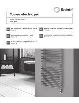
1. Installation
We recommend that the water heater is installed in the vicinity where hot water is required, in order to
reduce heat loss. The selected location should exclude the
possibility of splashing water from the shower or other
contacts with water. The appliance should be installed
on a wall by means of mounting brackets. Two screws
are used to x the device (minimum Ø 6 mm) rmly on
the wall. These are included in the mounting kit. The
installation templates either above or below the stack are
universal and allow the space between the bolts to vary
between 96 and 114mm.m.
IMPORTANT: The water heater models suitable to be installed below/above the battery are indicated on the water
heater. The water heater suitable for the installation below the stack are mounted in such a way that the outlet/
inlet of the pipes are pointed downwards (towards the oor). The water heater suitable for the installation on the
stack are mounted in such a way that the outlet/inlet of the pipes are pointed upwards (towards the ceiling).
ATTENTION: In order to avoid injury to the user and/or third parties in case of faults in the hot water supply
system, the appliance must be installed in facilities equipped with waterproof ooring. Do not place objects
that are not waterproof under the device under any circumstances.
min 96 mm
max 114 mm
8 mm
EN

6
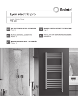
2. Hydraulic connections
1. Input pipe
2. Safety valve (0,8 MPa)
3. Reduction valve ( if the water supply pressure is
higher than a 0,6 MPa)
4. Shut-o valve
5. Discharge mouth to grid
6. Hose
7. Drain wrench
When connecting the water heater to the water supply system, pay attention to the indicative color markings
(rings) of the pipes: blue for cold water and red for hot water.
The assembly and installation of the return safety valve supplied with the water heater is mandatory for safety.
EXCEPTION: If local regulations require the use of another safety valve or device (complying with EN 1487 or
EN 1489 standards) they must be purchased separately. For devices that comply with the EN 1487 standard,
the maximum working pressure announced should be 0.7 MPa. For other safety valves, the pressure to which
it is calibrated must be 0.1 MPa less than that marked on the appliance plate. In these cases, the back-o valve,
which is supplied with the water heater, should not be used.
ATTENTION:
• You must not use any other return safety valve, other than the one supplied with the heater. The device may fail if any
other return safety valves are used.
• The presence of other or old reective protection valves can cause deterioration of the water heater, therefore they
must be removed.
• The xing of the safety return valve to cables greater than 10 mm in thickness is forbidden, as it could damage the valve
and render the water heater dangerous.
• The safety return valve and the pipe between the valve and the water heater must be protected against freezing.
During draining with the hose, the free end must always be open (not submerged). The hose should also be protected
against freezing.
2
6
2
6
7
2
1
4
5
3
2
4
3
1
5
Top connection water heater Bottom connection water heater
EN

7
The water heater tank is lled with water when you open the key in the cold water supply system and the hot
water faucet. After thr lling process, a constant ow of water must ow through the hot water tap. Once this
happens, the hot water tap can be closed.
When you want to empty the water heater tank, you must rst cut o the power supply.
Drainage procedure for above sink installation of the water heater:
1. Disconnect the water heater from the electric current.
2. Close the cold water supply tap
3. Open the hot water supply tap.
4. The water tap
7
must be opened to drain the water from the water tank. If there is no such outlet pipe,
the water can be drained as follows:
• Discharge the water from the water heater by raising the recoil lever of the safety valve.
• The water can be drained directly from the inlet pipe of the water tank that has been disconnected.
IMPORTANT: When emptying the water heater, take measures to avoid damage caused by water ow
Drainage procedure for below sink installation of the water heater:
1. Disconnect the water heater from the electric current.
2. Close the cold water supply tap.
3. Remove the water connection accessories from the water heater.
4. Remove the thermos from point of installation. Rotate it so that the outlets are oriented downwards and
pour the water into a container. Wait until all the water drains from the water heater.
If the pressure in the water network exceeds the amounts indicated in section 1, it is necessary to install a
pressure reduction valve, otherwise the water heater will not work properly. Rointe/the manufacturer does
not assume any responsibility for problems arising from incorrect use of the water heater.
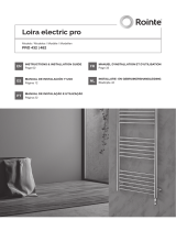
3. Electrical connections
Before turning on the water heater, ensure it has been correctly installed and is full of water.
A1 / L
A2 / L
B1 / N
B2 / N
T2
S
T1
R
1
2
001
s
L1
EN

8
Models supplied with a power cord with a plug must be plugged into a power outlet. The water heater can be
disconnected from the mains by unplugging it.
IMPORTANT: The outlet must be connected to a separate circuit provided with a safety mechanism. It must
be grounded.
For models equipped with a power cord without a plug, the appliance must be connected to an individual
electrical circuit of xed installation, equipped with a safety device with a nominal electrical current of 16A
(20A for power> 3700W). The connection must be constant (without a plug). The electrical circuit must be
equipped with a safety device and with a built-in mechanism that ensures the separation of all the poles in
case of type III overvoltage.
• Brown insulation cable to the phase cable of the electrical installation (L).
• Blue insulation cable to the neutral cable of the electrical installation (N).
• Yellow-green insulation conductor cable, to the protective cable of the electrical installation.
5. OPERATION
When you have performed the instructions described in
section 4 above, you can start using the water heater
(which has an indicator light)
1
.
The indicator light is turned on when the water heater
is connected to heat the water. The indicator light turns
o when the water reaches the selected temperature
and indicates that the water heater is not in operation
and is no longer heating water.
Ignition switch with 2 positions
3
:
• Position 0 = OFF. The water heater is not active
and does not heat water.
• Position I = ON. The water heater is regulated
automatically by the thermostat positions
4
.
Control of the thermostat with 5 positions
4
:
• Anti-Frost Position : set the thermostat at this point for a minimum level of water heating. In this
mode, the water heater switches on when the temperature of the water contained in the water tank
falls below 5ºC. It is suitable in cases of low potential water temperature.
NOTE: In this setting, the water heater maintains a temperature that does not allow the water to freeze. The power
supply for the water heater must be activated and the water heater switched on. The safety valve and the pipes must
be protected against freezing.
In the event that the power supply is interrupted for any reason, there is a danger that the water in the tank will
freeze. Therefore, it is recommended to drain the water from the water heater during long absences.
EN

9
• Position I (summer mode): The thermostat is in economical mode for low water temperature and
low power consumption. This mode is suitable when high water temperature is not necessary.
• Position II (winter mode): The thermostat is in optimal mode, with higher water temperature values.
This mode is suitable for when high water temperatures are necessary.
• Position
e
(energy saving mode): During this operating mode the water reaches a temperature of
approximately 60ºC for reduced heat loss.
• Position III (maximum mode): The thermostat is set in maximum operating mode, with very high
values of energy consumption and with maximum water temperature levels (around 70ºC). This is the
most suitable mode when a large volume of water with a pleasant temperature is needed.
6. PROTECTION AGAINST MAGNESIUM ANODE OXIDATION
The magnesium anode protects the inner surface of the water tank against corrosion.
The magnesium anode will deteriorate over time and is subject to periodic inspections. Rointe/the
manufacturer recommends a periodic inspection of the magnesium anode by an authorised technician and
if appropriate, during the periodic prophylaxis of the water heater.
To replace the magnesium anode, please contact the Rointe Technical Service on 0203 321 5929.
7. PERIODIC MAINTENANCE
Under normal operating conditions, and with a high temperature on the surface of the electrical resistance,
lime scale deposits can often occur. This worsens the exchange of heat between the resistance and the water,
causing the resistance to overheat along with typical noises of boiling water. The thermostat will turn on and
o more frequently. It is possible to activate the protection mode to avoid overheating. Because of this, the
Rointe/manufacturer recommend preventive maintenance every two years by an authorised installer from
the Rointe Technical Service (please call 0203 321 5929).
This maintenance should include cleaning and inspection of the anode, which should be replaced when
necessary.
To clean the appliance, use a damp cloth. Do not use abrasive cleansers or those containing solvents. Do not
pour water over the water heater.
ROINTE reserves the right to modify the characteristics and specications of its products without prior notice.
ROINTE is not responsible for any consequences arising should the instructions contained in this manual not
be followed.
EN

10
8. GUARANTEE
In this section, we hereby describe the guarantee conditions, which the buyer
acquires, on buying this product from ROINTE. These conditions comply with all
the rights construed in the national legislation in force, as well as any additional
rights and guarantees, which are oered by ROINTE.
Any incident that you might detect in your ROINTE product can be sorted by
the product seller or quickly by the manufacturer. Please contact ROINTE by
telephoning 0203 321 5929 for Technical Support. Alternatively, you can email
ROINTE at suppor[email protected], through which we will instruct you on how
to solve the incident.
You will need the product reference, serial number, date of purchase and the nature of the failure to
contact us to improve the warranty. Also attach a copy of the product purchase invoice.
8.1. ROINTE guarantees that there are no material defects of design or manufacture at the time of original
acquisition and guarantees the inner steel cylinder for a period of 24 months..
8.2. If during the guarantee period, the product does not work correctly under normal use, and any design,
material or manufacturing defect is found, ROINTE will repair or substitute the product as it may see t, in
accordance with the terms and conditions as follows:
8.2.1. The guarantee is only applicable if the original guarantee is issued by the seller and when the said
guarantee is lled in correctly including product reference, series number (marked on the product’s label
indicating technical features), purchase date and the seller’s stamp, and either registered on our website at www.
rointe.co.uk or returned completed to ROINTE within 90 days of installation. ROINTE reserves the right to reject
the guarantee service when this information has been removed or modied after the original product purchase.
8.2.2.1. Damage caused by negligence and/or misuse of the product, i.e. used for other purposes that
are not construed as its normal use or for not respecting the instructions of use and maintenance given by
ROINTE as well as incorrect installation or use of the product that may not comply with the current technical
standards of safety.
8.2.2.2. Corrosion of any part of the product caused by direct exposure to salt water. When the product is
installed no more than 200m from the coast the guarantee for damages caused by corrosion the period will
be reduced by 50%.
8.2.2.3. Any unauthorised modication of the product or repairs of the product carried out by third parties
or unauthorised technicians or opening of the product by third parties or unauthorised people.
8.2.2.4. Any accidents that are deemed outside the control of ROINTE, such as (but not limited to): lightning,
REFERENCE
SERIAL NUMBER
VENICE
VWI010DHWD4
1500W
EN

11
res, oods, natural disasters, public disorder, atmospheric or geologic phenomena etc.
8.2.2.5. Faults that result from an incorrect installation. Guidance can be found within the recommendations
for installation, by Rointe and in the installation manual. If in doubt, please contact ROINTE.
8.2.2.6. Aesthetic wear and tear produced by use, the cleaning of lime scale accumulation, revision and
substitution of the magnesium anode as well as other operations of maintenance of the product. Such repairs
will be charged to the user.
8.2.2. Any repairs or substitutions covered under this guarantee must be parts that are functionally equivalent.
The defective parts or parts removed or replaced shall become the property of ROINTE.
8.2.3. The product must be installed in a way that allows access for our technicians should they need to gain
access to the product for repair or maintenance. The user/client is responsible for any costs or organisation
required to provide access to the products for their repair and/or substitution.
8.2.4. The product has been installed indoors, in a frost free environment and has solely been used for the
purpose of heating potable water that complies with current (at time of installation) regulations and standards
and is not fed with water from a private source.
8.2.5. The product has not been subjected to excessive pressure or electrolytic actions from dissimilar
materials or attack from salt deposits.
8.3. The Technical Service department of ROINTE will advise you if you need to purchase any parts not covered
under the guarantee or out of guarantee.
8.4. This guarantee will be null and void if the product: has been manipulated, modied and/or repaired in any
way and/or by unauthorised persons. This guarantee will also be void if the product is not correctly installed.
8.5. This guarantee is not transferable and does not include claims due to frost or limescale damage.
8.6. Proof of purchase will be required to ROINTE for any claim.
8.7. This guarantee does not aect your statutory rights.
8.8. This guarantee does not aect the buyer’s legal rights stipulated in the current national legislation, nor
aects those rights against the distributor or installer that could come forth in compliance with the purchase
contract.
8.9. In the absence of a national legal legislation applicable, this guarantee shall prevail and may be construed
as the buyer’s only protection. ROINTE, its oces, distributors and installers may not be held responsible for
any accidental damage that emerges due to infringement of any rules implicitly related to this product.
9. EUROPEAN DIRECTIVE WEEE 2012/19/UE
Under the European Directive 2012/19/UE on Waste Electrical and Electronic Equipment (WEEE), the
product cannot be disposed in the usual council bins and containers. They must be separated to optimize
the recovery and recycling of all of the components and materials and reducing the impact to human
health and the environment. The symbol of the container crossed out over a horizontal line is marked
on all of ROINTE products to remind the consumer of the obligation to separate them on disposal. The
consumer should contact the local authority or original point of sale to learn more about the correct
disposal of this product.
EN

12
10. DIMENSIONS & TECHNICAL CHARACTERISTICS
MODELS
VWI010DHWD4 VWI015DHWD4 VWI010DHWU4 VWI015DHWU4
Volume (L) 10 15 10 15
Nominal power (W) 1,500 1,500 1,500 1,500
Outlet Bottom Bottom Top Top
DIMENSIONS
Width x height x depth (mm) 372 x 406 x 257 372 x 406 x 324 372 x 406 x 257 372 x 406 x 324
Distance between connections
(mm)
100 100 100 100
CHARACTERISTICS
Empty weight (kg) 7.6 9.4 7.6 9.4
100% capacity weight (kg) 17.6 24.4 17.6 24.4
Water connections (inches) 1/2” 1/2” 1/2” 1/2”
Finishes White RAL 9016 (tank) || Black RAL 9005 (control panel)
EAN CODE 8436045913159 8436045913166 8436045913616 8436045913623
406 mm
372 mm
257 mm 324 mm
406 mm
372 mm
257 mm 324 mm
TECHNICAL INFORMATION
Submerged copper heating element
Enamelled steel tank
Magnesium anode protector
CFC-free polyurethane insulation foam
External casing in ABS
Maximum working pressure (bars) 8
Protection Grade IPX4
Energy Classication B
FUNCTIONS
External thermal regulator dial
INSTALLATION
Installation position Vertical
Safety valve
SAFETY
Safety thermostat
REGULATIONS & GUARANTEES
2004/108/CE Electromagnetic comp.
2006/95/CE Low voltage directive
Guarantee 2 years
EN

1313
EN
CERTIFICATE OF GUARANTEE
Cut along the dotted line
In the event of any defect being detected in the product within the period of guarantee, you must ll in the below Certicate
of Guarantee and send it to us stamped together with a copy of the sales invoice via email to suppor[email protected]
or to the following postal address: INDUSTRIAS ROYAL TERMIC, S.L., C/E, Parcela 43, 30140 Santomera (Murcia, Spain).
CERTIFICATE OF GUARANTEE
REFERENCE:
Nº SERIES:
PURCHASE DATE:
USER:
HOME ADDRESS:
TOWN: POSTCODE:
COUNTY:
COUNTRY:
TELEPHONE: EMAIL:
SELLER’S STAMP:
NB: This certicate of Guarantee MUST be completed in full in order to obtain guarantee rights. The purchase date and seller’s stamp are
compulsory. Please attach a copy of your sales invoices. In addition, for new constructions include the Certicate of First Occupation.
EN

14

15
Termo A.C.S. eléctrico digital compacto
Venice
IMPORTANTE
Antes de utilizar los termos, le recomendamos que lea este manual de instrucciones para garantizar
un funcionamiento correcto. Este manual debe permanecer con el producto después de la instalación.
Contenido
1.
Modo de uso............. ..................................................................................................................................................................16
2.
Reglas importantes...................................................................................................................................................................16
3.
Descripción y principio de funcionamiento...........................................................................................................................16
4.
Instalación y encendido...........................................................................................................................................................17
5.
Operación...................................................................................................................................................................................20
6.
Protección contra el óxido del ánodo de magnesio...............................................................................................................21
7.
Mantenimiento......................................................................................................................................................................21
8.
Rointe Garantía..........................................................................................................................................................................22
9.
Directiva Europea......................................................................................................................................................................23
10.
Dimensiones y características técnicas..................................................................................................................................24
11.
Certicado de garantía.............................................................................................................................................................25
ATENCIÓN
Muchas gracias por elegir los termos para agua caliente sanitaria del modelo VENICE, fabricados con
componentes de máxima calidad pensados para usted.
Los termos para agua caliente sanitaria VENICE han superado los más exigentes controles de calidad
para cumplir con los más rigurosos requerimientos en seguridad. Antes de comenzar a usar los termos
para agua caliente sanitaria VENICE le recomendamos que lea con atención este manual, para poder
obtener su correcto funcionamiento con las máximas garantías.
ES

16
1. MODO DE USO
El termo tiene como n suministrar agua caliente sanitaria a los hogares equipados con un sistema de tuberías
que trabaje a una presión inferior a 6 bar (0,6 Mpa).
Está diseñado para funcionar en espacios cerrados en los que la temperatura no baje de los 4 grados.
El aparato no está diseñado para trabajar de forma continua.
2. REGLAS IMPORTANTES
• El termo debe montarse solamente en recintos con una seguridad anti incendios normal.
• No conecte el termo sin estar seguro que está lleno de agua.
• Durante la conexión del termo a la corriente eléctrica hay que tener especial cuidado al conectar el cable
de seguridad.
• Si se prevé que se van a alcanzar temperaturas de congelación, el termo debe ser completamente
vaciado.
• En funcionamiento (calentando agua), es normal que gotee el agua por la abertura de drenaje de la
válvula de seguridad. Ésta debe dejarse abierta. Se deben tomar medidas para recoger las fugas de agua
a n de evitar daños.
• Durante el proceso de calentamiento, la resistencia puede emitir un ligero ruido (agua hirviendo), lo
cual es habitual y no implica ningún problema. Sin embargo, si el ruido aumenta con el paso del tiempo
puede que la razón sea la acumulación de cal. Para eliminar el ruido será necesario limpiar el aparato
desincrustando la cal adherida. Este tipo de limpieza no está cubierta por la garantía.
• La válvula y sus componentes deben ser protegidos contra procesos de congelación.
• Para asegurar un funcionamiento correcto del termo, la válvula de retorno de seguridad debe someterse
a inspecciones y una limpieza periódica.
• Queda terminantemente prohibido realizar modicaciones o cambios tanto en la estructura como en
el circuito eléctrico del termo. Si se detecta alguna modicación durante la inspección del aparato, la
garantía quedará anulada inmediatamente. Por modicaciones o cambios se entienden: la eliminación
de piezas o componentes originales del fabricante, la incorporación de elementos adicionales en el
termo o el recambio de piezas por otros similares que no hayan ido aprobados por el fabricante.
• Si el cable de alimentación (en aquellos que lo incorporen) sufre daños, debe ser sustituido por el servicio
técnico ocial o por un profesional con la formación adecuada para ello, a n de evitar cualquier riesgo.
• Este aparato puede ser utilizado por niños de edad no inferior a los 8 años y por personas con capacidades
físicas, sensoriales o mentales reducidas, o con experiencia y conocimientos insucientes, siempre que
estén atentamente vigiladas o instruidas sobre la manera de utilizar de forma segura el aparato o sobre
los peligros que ello comporta. Asegúrese de que los niños no jueguen con el aparato.
3. DESCRIPCIÓN Y PRINCIPIO DE MANTENIMIENTO
El aparato se compone de un cuerpo, brida, panel de control de plástico, válvula de seguridad anti-retorno.
1.
El cuerpo está formado por un depósito de acero (tanque de agua) y carcasa de plástico (cubierta externa),
con aislamiento térmico colocado en el medio, y dos tubos con rosca G ½”, para el suministro de agua
ES

17
fría (marcado con un anillo azul) y la descarga de agua caliente (marcado con un anillo rojo). El interior
del depósito es de acero tratado contra la corrosión mediante un recubrimiento especial vitrocerámico.
2. La brida está equipada con una resistencia eléctrica y ánodo de magnesio. La brida se ja en el depósito
de agua con pernos.
La resistencia eléctrica calienta el agua en el tanque y es controlada por el termostato, que mantiene
automáticamente la temperatura programada.
El panel de control plástico incorpora: el interruptor de encendido (dependiendo del modelo), termostato regulable
(dependiendo del modelo), y luces de control. La protección térmica es un dispositivo que desconecta el termo de
la fuente de alimentación cuando la temperatura del agua alcanza valores excesivos. Si el dispositivo se acciona,
debe llamar al servicio técnico. Las luces de control (según el modelo) indican el modo actual de la unidad.
El ánodo de magnesio ofrece protección extra contra la corrosión en el tanque interior de los termos eléctricos,
equipados con recubrimiento de vidrio cerámico. La válvula de seguridad de retorno evita el vaciamiento
completo del aparato en caso de interrupción de suministro de agua fría. La válvula protege el aparato de los
aumentos de presión por encima del valor permitido durante el calentamiento, liberando el exceso de presión
a través de la salida de desagüe. El agua que gotea a través del desagüe durante el proceso de calentamiento
no indica ningún problema. Es algo normal que hay que tener en cuenta cuando el termo está instalado.
IMPORTANTE: La válvula de protección no puede garantizar la protección del aparato cuando la conducción
de agua se produce a una presión más alta que la determinada para el aparato.
4. INSTALACIÓN Y ENCENDIDO
1. Instalación
Se recomienda la instalación del termo eléctrico en las
proximidades de los lugares donde se utiliza el agua
caliente, con el n de reducir las pérdidas de calor durante
el transporte de agua. La ubicación seleccionada debe
excluir la posibilidad de salpicaduras de agua procedentes
de la ducha u otros contactos con el agua. El aparato se
colocará en una pared por medio de soportes de montaje.
Dos tornillos se utilizan para jar el aparato (mínimo Ø 6
mm) rmemente en la pared (incluido en el kit de montaje). Las plantillas de instalación por encima o por
debajo de la pila, es universal y permite que el espacio entre los pernos varíe entre 96 y 114mm.
IMPORTANTE: Aquellos modelos de termo eléctrico, apto para ser instalados por debajo/por encima de la pila, vienen
indicados en el aparato. Los termos diseñados para la instalación debajo de la pila están montados de tal manera que
la salida/entrada de las tuberías se señalan hacia abajo (para el suelo). Los termos diseñados para la instalación sobre
la pila, están montados de tal manera que la salida/entrada de las tuberías se señalan hacia arriba (hacia el techo).
ATENCIÓN: Con el n de evitar lesiones al usuario y/o de terceras personas en caso de fallos en el sistema de
abastecimiento de agua caliente, el aparato debe ser montado en las instalaciones equipadas con el suelo
impermeabilizado. No coloque objetos que no sean impermeables bajo el aparato bajo ninguna circunstancia.
min 96 mm
max 114 mm
8 mm
ES

18
2. Conexión hidráulica del termo
1. Tubería de entrada
2. Válvula de seguridad (0,8 MPa)
3. Válvula de reducción ( si la presión del suministro
de agua es superior a 0,6 MPa)
4. Válvula de cierre
5. Boca de descarga a rejilla
6. Manguera
7. Llave de drenaje
Al conectar el termo, al sistema de abastecimiento de agua, preste atención a las marcas de color indicativo
(anillos) de las tuberías: Azul para el agua fría y Rojo para el agua caliente.
El montaje de la válvula de seguridad de retorno suministrado con el termo es obligatorio por seguridad.
EXCEPCIÓN: Si las regulaciones locales requieren usar otra válvula de seguridad o dispositivo (que cumplen
las normas EN 1487 o EN 1489) estos deben comprarse por separado. Para dispositivos que cumplen la norma
EN 1487, la presión máxima de trabajo anunciada debe ser de 0,7 MPa. Para otras válvulas de seguridad, la
presión al que está calibrado debe ser con 0,1 MPa menor que el marcado en la placa del aparato. En estos
casos, la válvula de retroceso, que se suministra con el aparato, no debe ser utilizada.
ATENCIÓN:
• Cualquier otra válvula de seguridad de retorno puede conducir a un fallo del aparato, por lo tanto, deben
ser eliminados.
• La presencia de otras o viejas válvulas de protección reexiva pueden provocar un deterioro de su
aparato, por lo que deben ser eliminadas.
• No está permitida la jación de la válvula de retorno de seguridad a cables superiores a 10 mm de espesor,
ya que podría dañar la válvula y podrían hacer que el uso del aparato sea peligroso.
• La válvula de retorno de seguridad y la tubería entre la válvula y el termo deben ser protegidas contra
la congelación. Durante el drenaje con la manguera, el extremo libre debe estar siempre abierto (no
sumergido). La manguera también deberá estar protegida contra congelación.
El termo se llena de agua al abrir la llave en el sistema de suministro de agua fría y la llave del agua caliente.
Después de proceso de llenado, un ujo constante de agua debe uir por el grifo de agua caliente. Una vez
2
6
7
2
1
4
5
3
2
6
2
4
3
1
5
Termo de conexión superior Termo de conexión inferior
ES

19
que esto sucede, ya se puede cerrar el grifo de agua caliente. Cuando se desee vaciar el termo, primero deberá
cortar su suministro eléctrico.
Procedimiento de drenaje para termos de instalación sobre el fregadero:
1. Desconectar el termo de la corriente eléctrica.
2. Cerrar la llave de suministro de agua fría.
3. Abrir la llave de agua caliente en el grifo.
4. El grifo del agua
7
se debe abrir para drenar el agua del tanque de agua. Si no existe dicha tubería de
salida, el agua puede drenarse de la siguiente manera:
• Descargue el agua del termo levantando la palanca de retroceso de la válvula de seguridad.
• El agua puede drenarse directamente de la tubería de entrada del depósito de agua, previamente
desconectada.
IMPORTANTE: Al vaciar el termo, tome medidas para evitar los daños que pueda provocar el ujo de agua.
Procedimiento de drenaje para termos de instalación bajo el fregadero:
1. Desconectar el termo de la corriente eléctrica.
2. Cerrar la llave de suministro de agua fría.
3. Desmontar los accesorios de conexión de agua del termo.
4. Desmontar el termo de su lugar de instalación, girarlo de forma que las tomas se orienten hacia abajo y
verter el agua en un recipiente preparado a tal efecto. Esperar hasta que toda el agua se drene del termo.
Si la presión en la red de agua supera a las cantidades los indicados en el punto 1 (modo de uso), es necesaria
la instalación de una válvula de reducción de presión, de lo contrario el termo no funcionará correctamente.
El productor no asume la responsabilidad de los problemas causados por el uso incorrecto del aparato.
El fabricante no asume ninguna responsabilidad por problemas derivados del uso inapropiado del aparato.
3. Conexión eléctrica del termo
Antes de encender el aparato, asegúrese de que el aparato esté lleno de agua.
A1 / L
A2 / L
B1 / N
B2 / N
T2
S
T1
R
1
2
001
s
L1
ES

20
Los modelos provistos con cable de alimentación eléctrica con un enchufe deberán ser enchufados a una
toma de corriente. El termo puede desconectarse de la red eléctrica desenchufándolo.
IMPORTANTE: La toma debe estar conectada a un circuito separado provisto de un mecanismo de seguridad.
Debe estar conectado a tierra.
Para modelos equipados con cable de alimentación sin clavija de enchufe, el aparato debe conectarse a un
circuito eléctrico individual de la instalación ja, equipado con un dispositivo de seguridad con corriente
eléctrica nominal de 16A (20A para potencia >3700W). La conexión debe ser constante (sin clavija de enchufe.
El circuito eléctrico debe estar equipado con dispositivo de seguridad y con un mecanismo incorporado que
asegure la separación de todos los polos en caso de sobretensión tipo III.
Los cables de alimentación del aparato deben conectarse de la manera siguiente:
• Cable de aislamiento marrón al cable de fase de la instalación eléctrica (L).
• Cable de aislamiento azul al cable de neutro de la instalación eléctrica (N).
• Cable conductor de aislamiento amarillo-verde, al cable protector de la instalación eléctrica
5. OPERACIÓN
Cuando ha realizado las instrucciones descriptas en el
punto 4 anterior, puede empezar a usar el aparato. El
aparato tiene lámpara indicadora
1
.
Lámpara se enciende cuando el termo se conecta para
calentar el agua. Lámpara se apaga cuando el agua
alcanza la temperatura seleccionada y se indica que el
aparato no está en funcionamiento.
Interruptor de encendido con 2 posiciones
3
:
• Posición 0: Apagado. El termo no calienta agua.
• Posición I: Encendido. La calefacción del agua se
regula automáticamente por las posiciones del
termostato
4
.
Control del termostato con 5 posiciones
4
:
• Posición Anti-Frost : Coloque el termostato en este punto para un nivel mínimo de calentamiento
de agua. En este modo, el termo se enciende cuando la temperatura del agua contenida en el depósito
de agua baja de los 5ºC. Es conveniente en los casos de baja temperatura potencial del agua.
NOTA: En este ajuste, el aparato mantiene una temperatura que no permite que el agua se congele. El suministro
eléctrico para el aparato debe estar activado y el aparato encendido. La válvula de seguridad y las tuberías deben
estar protegidas contra congelación.
En el caso de que por cualquier motivo se interrumpiera el suministro de energía, existe el peligro que el depósito se
congele. Por lo tanto, se recomienda vaciar el agua del termo en caso de larga ausencia.
ES
/