ClearOne CONVERGE Pro 2 Guide de démarrage rapide
- Taper
- Guide de démarrage rapide

CONVERGE
®
PRO 2
Next Generation Audio DSP Platform
Professional Audio Conferencing and Sound Reinforcement Systems
QUICK-START GUIDE

TABLE OF CONTENTS
CONVERGE PRO 2 OVERVIEW � � � � � � � � � � � � � � � � � � � � � � � � � � � � � � � � � � � � 3
OPERATING REQUIREMENTS � � � � � � � � � � � � � � � � � � � � � � � � � � � � � � � � � � � � � 3
SYSTEM REQUIREMENTS� � � � � � � � � � � � � � � � � � � � � � � � � � � � � � � � � � � � � � � � 3
IMPORTANT SAFETY INFORMATION � � � � � � � � � � � � � � � � � � � � � � � � � � � � � � � � 4
UNPACKING � � � � � � � � � � � � � � � � � � � � � � � � � � � � � � � � � � � � � � � � � � � � � � � � � 5
MOUNTING� � � � � � � � � � � � � � � � � � � � � � � � � � � � � � � � � � � � � � � � � � � � � � � � � � 6
CONTROLS & CONNECTIONS � � � � � � � � � � � � � � � � � � � � � � � � � � � � � � � � � � � � 7
CONVERGE PRO 2 FRONT PANELS . . . . . . . . . . . . . . . . . . . . . . . . . . . . . . . . . . . . . . . . . . . . . . . . . . . . . . . 7
CONVERGE PRO 2 REAR PANELS . . . . . . . . . . . . . . . . . . . . . . . . . . . . . . . . . . . . . . . . . . . . . . . . . . . . . . . . 7
CONFIGURING THE CONVERGE PRO 2 � � � � � � � � � � � � � � � � � � � � � � � � � � � � � 10
APPLICATION PROGRAMMER’S INTERFACE� � � � � � � � � � � � � � � � � � � � � � � � � � 10
COMPLIANCE � � � � � � � � � � � � � � � � � � � � � � � � � � � � � � � � � � � � � � � � � � � � � � � 10

3
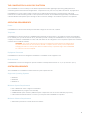
THE CONVERGE PRO 2 AUDIO DSP PLATFORM
The CONVERGE Pro 2 is the industry’s most advanced professional audio digital signal processing (DSP) platform for
conferencing and sound reinforcement applications. It outperforms in any size room, any audio environment, any application.
CONVERGE Pro 2 meets a diverse range of needs, from pc-based videoconferencing, teleconferencing, VoIP, sound
reinforcement to audio networking needs. It is also optimized to work with the new Beamforming Mic Array 2 and DIALOG 20
2-Channel Wireless Microphone System through its native connection, adding to the seamless experience of the platform.
OPERATING REQUIREMENTS
Power
CONVERGE Pro 2 devices automatically accommodate voltages of 100–240 V AC, 50/60Hz.
Telephone
CONVERGE Pro 2 devices operate on a standard analog telephone line and connect to the telephone system with a standard
RJ-11 modular jack. If you do not have an RJ-11 jack where you want to install your CONVERGE Pro 2, call your local telephone
company for installation. CONVERGE Pro 2 48T, 128T, and 128TD can be configured to meet compliance requirements of different
countries via the CONSOLE software.
Equipment Placement
CONVERGE Pro 2 devices are designed for installation in a standard 19-inch equipment rack.
Environmental
CONVERGE Pro 2 devices are designed to operate at ambient unit temperatures between 14° F (-10° C) and 104° F (40° C).
SYSTEM REQUIREMENTS
The CONVERGE Pro 2 CONSOLE software minimum system requirements are:
Supported Operating Systems
• Windows 7
• Windows 8
• Windows 10
Minimum System Requirements
• Intel or AMD 6 with 1GHz or higher recommended
• 2GB RAM Minimum (or higher recommended)
• 500MB hard disk space minimum (Additional space is required to store the site files and other project files)
• USB or Ethernet Network Interface to connect your computer with CONVERGE Pro 2 product
Minimum Software Requirements
• Administrator permission to install and run the software
WARNING: The country code must be set correctly in CONSOLE to ensure that the unit operates prop-
erly when connected to the telco network, and that it complies with the country’s telco requirements.
Changing this code to a country other than the intended country of operation might cause CONVERGE
Pro 2 devices to be non-compliant.

4
IMPORTANT SAFETY INFORMATION
Read all safety information before using this product.
1. Read these instructions.
2. Keep these instructions.
3. Heed all warnings.
4. Follow all instructions.
5. Do not use this apparatus near water.
6. Clean only with dry cloth.
7. Do not block any ventilation openings. Install in accordance with the manufacturer’s instructions.
8. Do not install near any heat sources such as radiators, heat registers, stoves, or other apparatus (including amplifiers) that produce heat.
9. Do not defeat the safety purpose of the polarized or grounding-type plug. A polarized plug has two blades with one wider than the other. A
grounding type plug has two blades and a third grounding prong. The wide blade or the third prong are provided for your safety. If the provided
plug does not fit into your outlet, consult an electrician for replacement of the obsolete outlet. The device must be connected to a earth
grounded socket. For Norway: Apparatet må tilkoples jordet stikkontakt. For Sweden: Apparaten skall anslutas till jordat uttag. For Finland: Laite
on liitettävä suojakoskettimilla varustettuun pistorasiaan.
10. Protect the power cord from being walked on or pinched particularly at plugs, convenience receptacles, and the point where they exit from the
apparatus.
11. Only use attachments/accessories specified by the manufacturer.
12. Use only with the cart, stand, tripod, bracket, or table specified by the manufacturer, or sold with the apparatus. When a cart is used, use
caution when moving the cart/apparatus combination to avoid injury from tip-over.
13. Unplug this apparatus during lightning storms or when unused for long periods of time.
14. Refer all servicing to qualified service personnel. Servicing is required when the apparatus has been damaged in any way, such as power-
supply cord or plug is damaged, liquid has been spilled or objects have fallen into the apparatus, the apparatus has been exposed to rain or
moisture, does not operate normally, or has been dropped.
15. Use the mains plug to disconnect the apparatus from the AC mains. The mains plug shall remain readily operable. For France: Utilisez la prise
secteur pour débrancher l’appareil à partir du secteur. La prise secteur doit rester facilement accessible.
16. To completely disconnect unit power from the AC mains, disconnect the unit’s power cord from the mains socket. To reconnect power, plug
the unit’s power cord into the mains socket following all safety instructions and guidelines. For France: Pour alimentation de l’unité de couper
entièrement l’alimentation secteur, débranchez le cordon d’alimentation de l’appareil de la prise de courant. Pour rétablir le courant, branchez le
cordon d’alimentation de l’appareil dans la prise de courant en suivant toutes les instructions et les directives de sécurité.
17. Caution: Danger of explosion if lithium battery is incorrectly replaced. Replace only with the same or equivalent type. Battery should only be
replaced by qualified personnel and is not intended as a user serviceable part. Do not expose batteries or battery pack to excessive heat
such as prolonged sunlight, fire or other heat sources. For France: Attention: Danger d’explosion si la pile au lithium est remplacée de façon
incorrecte. Remplacez uniquement avec le même type ou équivalent. Batterie ne doit être remplacé par du personnel qualifié et ne vise
pas comme une partie réparable par l’utilisateur. Ne pas exposer les piles ou batterie à une chaleur excessive comme la lumière du soleil
prolongée, le feu ou d’autres sources de chaleur.
18. Never push objects of any kind into this product through cabinet slots as they may touch dangerous voltage points or short out parts that could
result in fire or electric shock.
19. This product can interfere with electrical equipment such as tape recorders, TV sets, radios, computers and microwave ovens if placed in close
proximity.
20. Class 2 Wiring IS REQUIRED for these devices. Wiring and install should only be performed by qualified personnel.
21. For CONVERGE Pro 2 products that include a telephone circuit, Underwriters Laboratories (UL) requires these safety notifications:
Caution: To reduce the risk of re, use only No. 26 AWG or larger UL Listed or CSA Certied Telecommunication Line Cord.
• When using your telephone equipment, basic safety precautions should always be followed to reduce the risk of re, electric shock and injury to
persons, including the following:
• Do not use this product near water for example, near a bathtub, washbowl, kitchen sink or laundry tub, in a wet basement or near a swimming pool.
• Avoid using a telephone (other than a cordless type) during an electrical storm. There may be a remote risk of electric shock from lightning.
• Do not use the telephone to report a gas leak in the vicinity of the leak.
• Use only the power cord and batteries indicated in this manual. Do not dispose of batteries in a re. They may explode. Check with local codes for
possible special disposal instructions.
Use only at altitudes of 2000
meters or less.
AVIS: RISQUE DE CHOC
ELECTRIQUE - NE PAS OUVRIR
Save These Instructions

5
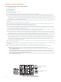
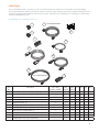
UNPACKING
Use the illustrations below to verify that you have received all components. ClearOne is not responsible for product damage
incurred during shipment. Inspect your shipment carefully for obvious signs of damage. If the shipment appears damaged, retain
original boxes and packing material for inspection by the carrier, and contact them immediately. The following items are included
with your CONVERGE Pro 2 unit:
CONVERGE Pro 2 Package Contents
4
8
7
5
TELCO VERSIONS ONLY
3
1
2
9
6
VOIP VERSIONS ONLY
10
Item
No.
Description 128, 128D,
128SR, 128SRD
128T,
128TD
128V,
128VD
120 012 48T 48V
1 Terminal Block Connector, 3 pos. (Orange) 12 12 12 12 0 4 4
2 Terminal Block Connector, 3-Pos. (Black) 8 8 8 0 12 8 8
3 #10-32 Screw/Washer Kit 1 1 1 1 1 1 1
4 Grounded Power Cord 6’ 1 1 1 1 1 1 1
5 Telephone Cable, 12’ 0 1 0 0 0 1 0
6 RJ-45/RJ-45 Patch Cable, 7’ 0 0 1 0 0 0 1
7 RJ-45/RJ45 Patch Cable, 18’ 1 1 1 1 1 1 1
8 USB Type A to Type B Cable, 6’ 1 1 1 1 1 1 1
9 Terminal Block Connector, 6 pos. (Green) 1 1 1 1 1 1 1
10 Rack Ears Kit 1 1 1 1 1 1 1
11 CONVERGE Pro 2 Quick Start Guide 1 1 1 1 1 1 1

6
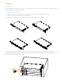
MOUNTING
Installation
Your CONVERGE Pro 2 product comes with rack mount ears that fit a standard 19” rack, and a screw/washer kit. Rack mounting elimi-
nates the need for space between multiple units.
To change position of your rack ears:
1. Remove two screws from each side near front/rear (depending on which side you want facing front of rack),
2. Attach rack ears using screws that were removed previously.
The following shows two options: 1) mounting to the front (standard) and 2) mounting to the back.
Mount the unit by securing the rack-mount ears to two posts or mounting strips in the rack using the four screws and washers
provided. Because the rack-mount ears support the weight of the entire chassis, be sure to use all four screws and washers to fasten
the two rack-mount brackets to the rack posts.
3

7
A
B
C
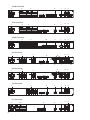
CONVERGE Pro 2 Rear Panels
128 & 128SR Rear Panels
1 2 3 4
5 6 7 8
1 2 3 4 5 6
7 8 9 10 11 12
GPIO
RS-232 P-Link Out
C-Link InP-Link PoE
C-Link Out
+5V 1 2 3 4
1
2
3
5
6
7
8
9
4
128D & 128SRD Rear Panels
GPIO
SecPri RS-232 P-Link Out
C-Link InP-Link PoE
C-Link Out
+5V 1 2 3 4
1 2 3 4
5 6 7 8
1 2 3 4 5 6
7 8 9 10 11 12
1 2
3 76
8 9
4 5
11
128T Rear Panel
1
2
3
5
4
6
7
8
9
Telco
1 2 3 4
5 6 7 8
1 2 3 4 5 6
7 8 9 10 11 12
GPIO
RS-232 P-Link Out
C-Link InP-Link PoE
C-Link Out
+5V 1 2 3 4
13
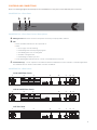
CONTROLS AND CONNECTIONS
Refer to the following diagrams and descriptions for CONVERGE Pro 2 front panel controls and back panel connectors.
CONVERGE Pro 2 Front Panel
CONVERGE Pro 2 Front Panel Control Descriptions
A. USB Type B Port: Provides convenient front panel connectivity for laptops, MAC, and PCs.
B. LED
» Power: Solid blue indicates the unit is powered on.
» Status:
• Off (no light): Unit still initializing
• Fast blinking blue: Stack Syncing in progress
• Slow blinking blue: Unit not configured
• Solid blue: Configured unit
• Fast blinking red: Stack Sync error
» Locate: Blinking blue indicates that the “Locate” command has been received.
C. Locate Button (C): “Locate” Capacitive Touch Button identifies hardware devices from software, or software applications
from hardware devices. Shows model number, unit name, IP address.

8
48V Rear Panel
1
2
4
5
10
6
7
8
9
3
12
120 Rear Panel
1 2 3 4 5 6
7 8 9 10 11 12
GPIO
RS-232 P-Link Out
C-Link InP-Link PoE
C-Link Out
+5V 1 2 3 4
1 3
5
4
6
7
8
9
012 Rear Panel
1
2
5
6
7
8
9
4
128TD Rear Panel
Telco
GPIO
SecPri RS-232 P-Link Out
C-Link InP-Link PoE
C-Link Out
+5V 1 2 3 4
1 2 3 4
5 6 7 8
1 2 3 4 5 6
7 8 9 10 11 12
1
2
3
4
5
7
6
8
9
13
11
128V Rear Panel
1 2 3 4
5 6 7 8
1 2 3 4 5 6
7 8 9 10 11 12
GPIO
RS-232 P-Link Out
C-Link InP-Link PoE
C-Link Out
+5V 1 2 3 4
1
2
3
4
5
10
6
7
8
9
128VD Rear Panel
GPIO
SecPri RS-232 P-Link Out
C-Link InP-Link PoE
C-Link Out
+5V 1 2 3 4
1 2 3 4
5 6 7 8
1 2 3 4 5 6
7 8 9 10 11 12
1 2 3 710 8 9
4 5
11
6
48T Rear Panel
1
2
3
5
4
6
7
8
9
12
13

9
CONVERGE Pro 2 (CP2) Rear Panel Connectors
1. AC Power: IEC connector, 100 – 240VAC auto-adjusting, 50/60Hz.
Warning: This equipment must be connected to an AC mains socket outlet with a protective earthing connection. The
third prong of this connector (ground) is an important safety feature. Do not attempt to disable this ground connection
by using an adaptor or other method.
2. Mic/Line Outputs: Mini-terminal push-on connector for line-level outputs (128, 128D, 128T, 128TD, 128V, 128VD, 48T, 48V,
012, 128SR, 128SRD).
3. Mic/Line Inputs: Mini-terminal push-on block connector for any combination of microphone and/or line level inputs. (128,
128D, 128T, 128TD, 128V, 128VD, 120, 128SR, 128SRD: 12 inputs. 48T and 48V: 4 inputs).
4. GPIO: Mini-terminal push-on block connector for control, status, variable voltage control.
5. Type B USB Port: Provides bi-directional audio connectivity between laptops/MAC/PCs and CP2 units.
6. LAN Ethernet Port: A RJ-45 10/100Mbps auto-sensing Ethernet port. The LAN port connects CP2 devices to a network.
7. RS-232 Serial Port: Female DB9 connector for connecting to a laptop, computer, or remote control serial devices (such
as AMX and Crestron controllers).
NOTE: CONVERGE CONSOLE software connects through USB or Ethernet only.
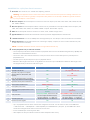
8. P-Link (Peripheral Link) In and Link Out Ports:
» The P-link ports provide Power, Audio & Control for peripheral devices such as the Beamforming Mic Array 2 (BFM2) and
DIALOG 20 2 Channel Wireless Receiver.
» The P-Link In Port is also used as PoE-In Port, so this port can be used to connect PoE Injector to provide power to
peripheral devices.
» One PoE injector can provide power for up to 3 peripheral devices.
» Maximum cable length is 650 feet for a Long Distance P-Link chain of up to 3 BFM2 units. Maximum cable length is 200
feet (Regular P-Link) for all other P-Link device types.
» Up to 12 peripheral devices can be connected in a Regular P-Link chain. You can connect 3 each of the BFM2 units
+ DIALOG 20 units + USB Expander + GPIO Expander per CONVERGE Pro 2 (CP2) unit. Up to 6 BFM2 units can be
connected in a Regular P-Link chain to a stack of two CP2 units.
» It uses a standard (not crossover) patch cable.
» LEDs adjacent to each port indicate connection status and packet traffic activity.
S. No. Feature Regular P-Link Long Distance P-Link
1 Applicable to all CP2 units YES
NO
(only supports CP2 AEC units)
2
Applicable to all peripheral units (BFM2,
DIALOG 20 Receiver, USB Expander, GPIO
Expander)
YES
NO
(only supports BFM2)
3
Same CP2 and BFM2 hardware (no hardware
changes, only software and firmware upgrades)
YES YES
4 Applicable to already sold and installed units YES YES
5 Maximum distance between units 200 feet (~60 meters) 650 feet (~200 meters)
6 Carries power, audio, control YES YES
7
Maximum number of peripheral devices in one
P-Link chain
12
(3 each: BFM2, DIALOG 20, USB Expander, GPIO
Expander)
3
(3 BFM2 only)
8 Cable specification
CAT5e/CAT6, 24 AWG, solid conductor cable.
Do not use Copper Clad Aluminum (CCA).
CAT6, 550 MHz, 23 AWG, solid conductor cable.
Do not use Copper Clad Aluminum (CCA).
9 PoE Power Injector spec
56V, Mode B, Midspan – For 3 BFM2 units
48V, Mode B, Midspan – For 1 BFM2 unit
56V, Mode B, Midspan – For 3 BFM2 units
48V, Mode B, Midspan – For 1 BFM2 unit
10 No extra cost, free to upgrade YES YES

10
9. C-Link In and Link Out Ports: Two RJ-45 E-bus (expansion bus) connectors used to connect multiple CONVERGE Pro
2 units together to create a site. You can connect any combination of CONVERGE Pro 2 units, where the total number of
microphone inputs does not exceed 96. Maximum cable length is 150 feet using solid core, factory terminated Category
5e or 6 cable.
WARNING: Use the C-Link In and C-Link Out ports with CONVERGE Pro 2 Devices ONLY. Connecting ANY other
devices to the C-Link In and C-Link Out ports, including CONVERGE Pro or Beamforming Microphone Array products
will result in severe equipment damage.
10. VoIP: A RJ-45 10/100Mbps auto-sensing Ethernet port connecting to 5 lines, with each line supporting
up to 5 calls (128V, 128VD, 48V).
11. Dante Primary & Secondary Ports: Two RJ-45 100/1000 Mbps Ethernet connectors for connecting to
primary and secondary Dante networks. Maximum cable length is 328 feet (128D, 128TD, 128VD, 128SRD).
12. 2-Channel Speaker Posts: Twopost/bananaplugconnectorsusedtoconnectanexternalspeaker(4Ω–16Ω).
Internal power amplifiers eliminate the need for an external power amplifier (48T, 48V).
13. Telco Line Port: One RJ-11 connector telephone port. The Telco port connects an analog telephone line
to CONVERGE Pro 2 devices (128T, 128TD, 48T).
NOTE: The Telco port is not available for use when the telephone hybrid is off-hook.
CONFIGURING THE CONVERGE PRO 2
CONVERGE Pro 2 CONSOLE software is required for configuring CONVERGE Pro 2 units. Configuration instructions can be
found in the CONVERGE Pro 2 Installation and User Manual at www.clearone.com.
APPLICATION PROGRAMMER’S INTERFACE
The CONVERGE Pro 2 Serial Commands Reference Guide is available for viewing or download at www.clearone.com.
COMPLIANCE
CE COMPLIANCE
Details on CE compliance can be found on the ClearOne website under “Resource Library”.
FCC PART 68 COMPLIANCE
US:FBIBR01ACNVRGPRO2
Ringer Equivalence Number (REN): 0.1A
This equipment complies with Part 68 of the FCC Rules Requirements adopted by ACTA. On the mixer unit of this equipment contains, among
other information, a product identifier in the format US:AAAEQ##TXXXX. If requested, this information must be provided to your telephone
company.
The REN is used to determine the number of devices that may be connected to the telephone line. Excessive RENs on the telephone line may
result in the devices not ringing in response to an incoming call. In most, but not all areas, the sum of the RENs should not exceed five (5.0). To
be certain of the number of devices that may be connected to the line, as determined by the total RENs, contact the telephone company to obtain
the maximum RENs for the calling area. The REN for this product is part of the product identifier that has the format US:AAAEQ##TXXXX. The
digits represented by ## are the REN without a decimal point (e.g. 03 is a REN of 0.3).

11
If this equipment causes harm to the telephone network, the telephone company will notify you in advance that temporary discontinuance of
service may be required. But if advance notice isn’t practical, the telephone company will notify the customer as soon as possible. Also, you will
be advised of your right to file a complaint with the FCC if you believe it is necessary.
The telephone company may make changes in its facilities, equipment, operations, or procedures that could affect the operation of the
equipment. If this happens, the telephone company will provide advance notice in order for you to make the necessary modifications to maintain
uninterrupted service.
This equipment uses an RJ11C jack that is used to connect this equipment to the premises wiring and telephone network. This RJ11C jack
complies with the applicable FCC Part 68 Rules and Requirements adopted by the ACTA.
A compliant telephone cord and modular plug is provided with this product. It is designed to be connected to a compatible modular jack that is
also compliant. See installation instructions for details.
WARNING: The country code must be set correctly in CONSOLE to ensure that the unit operates properly when connected to the telco network,
and that it complies with the country’s telco requirements.
Changing this code to a country other than the intended country of operation might cause CONVERGE Pro 2 devices to be non-compliant.
If you experience problems with this equipment, contact: ClearOne, Inc., 5225 Wiley Post Way, Suite 500Salt Lake City, Utah 84116, or by phone
at (800) 945-7730 for repair and warranty information. If the equipment is causing harm to the telephone network, the telephone company may
request you disconnect the equipment until the problem is resolved.
No user serviceable parts are contained in this product. If damage or malfunction occurs, contact ClearOne Inc. for instructions on its repair or
return.
Connection to party line service is subject to state tariffs. Contact the state public utility commission, public service commission or corporation
commission for information. This equipment cannot be used on telephone company provided coin service.
If your home has specially wired alarm equipment connected to the telephone line, ensure the installation of this equipment does not disable your
alarm equipment. If you have questions about what will disable alarm equipment,
IC COMPLIANCE
IC: 1970A-CNVRGPRO2
Ringer Equivalence Number (REN): 0.1
This product meets the applicable Industry Canada technical specifications. / Le présent matériel est conforme aux specifications techniques
applicables d’Industrie Canada.
The Ringer Equivalence Number (REN) is an indication of the maximum number of devices allowed to be connected to a telephone interface. The
termination of an interface may consist of any combination of devices subject only to the requirement that the sum of the RENs of all the devices
not exceed five. / L’indice d’équivalence de la sonnerie (IES) sert à indiquer le nombre maximal de terminaux qui peuvent être raccordés à une
interface téléphonique. La terminaison d’une interface peut consister en une combinaison quelconque de dispositifs, à la seule condition que la
somme d’indices d’équivalence de la sonnerie de tous les dispositifs n’excède pas cinq.
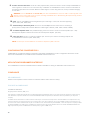
CONTACT INFORMATION
Headquarters
5225 Wiley Post Way,
Suite 500
Salt Lake City, UT 84116
US & Canada
Tel: 801.975.7200
TollFree: 800.945.7730
Fax: 801.303.5711
Other product names may be registered trademarks of their respective owners who do not necessarily endorse ClearOne or ClearOne’s products. All rights reserved. Information in this
document subject to change without notice. QSG-0032-001 Rev1.5 © 2018 ClearOne.
International
Tel: +1.801.975.7200
TechSupport
Tel: 801.974.3760
Sales
Tel: 801.975.7200
-
 1
1
-
 2
2
-
 3
3
-
 4
4
-
 5
5
-
 6
6
-
 7
7
-
 8
8
-
 9
9
-
 10
10
-
 11
11


ClearOne CONVERGE Pro 2 Guide de démarrage rapide
- Taper
- Guide de démarrage rapide
dans d''autres langues
Documents connexes
Autres documents
-
Crestron DMPS3-200-C Information produit
-
Crestron DSP-1282 Information produit
-
-
Allworx Tx 92/24 Guide d'installation
-
Xtorm XA082 Manuel utilisateur
-
Valcom VIP-415 Guide d'installation
-
xtrom XA2030 Manuel utilisateur
-
Xtorm XA2065 Manuel utilisateur
-
-
Barco Athena Guide d'installation