
P/NO.:MFL68065212
REV.00_190117
www.lg.com
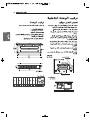
INSTALLATION MANUAL
Ceiling Concealed Duct
AIR
CONDITIONER
Please read this installation manual completely before installing the product.
Installation work must be performed in accordance with the national wiring
standards by authorized personnel only.
Please retain this installation manual for future reference after reading it
thoroughly.
ENGLISH
FRANÇAIS
1,MFL67939925,영어 2017. 7. 17. 오후 2:33 페이지 1

• Do not cool excessively indoors. This may be harmful for your health and may consume more
electricity.
• Block sunlight with blinds or curtains while you are operating the air conditioner.
• Keep doors or windows closed tightly while you are operating the air conditioner.
• Adjust the direction of the air flow vertically or horizontally to circulate indoor air.
• Speed up the fan to cool or warm indoor air quickly, in a short period of time.
• Open windows regularly for ventilation as the indoor air quality may deteriorate if the air condition-
er is used for many hours.
• Clean the air filter once every 2 weeks. Dust and impurities collected in the air filter may block the
air flow or weaken the cooling / dehumidifying functions.
For your records
Staple your receipt to this page in case you need it to prove the date of purchase or for warranty
purposes. Write the model number and the serial number here:
Model number :
Serial number :
You can find them on a label on the side of each unit.
Dealer’s name :
Date of purchase :
Here are some tips that will help you minimize the power consumption when you use the air
conditioner. You can use your air conditioner more efficiently by referring to the instructions
below:
TIPS FOR SAVING ENERGY
ENGLISH
TIPS FOR SAVING ENERGY
2
1,MFL67939925,영어 2017. 7. 17. 오후 2:33 페이지 2

3
IMPORTANT SAFETY INSTRUCTIONS
READ ALL INSTRUCTIONS BEFORE USING THE APPLIANCE.
Always comply with the following precautions to avoid dangerous situations and ensure peak
performance of your product
WARNING
It can result in serious injury or death when the directions are ignored
CAUTION
It can result in minor injury or product damage when the directions are ignored
WARNING
• Installation or repairs made by unqualified persons can result in hazards to you and others.
• Installation of all field wiring and components MUST conform with local building codes or, in
the absence of local codes, with the National Electrical Code 70 and the National Building
Construction and Safety Code or Canadian Electrical code and National Building Code of
Canada.
• The information contained in the manual is intended for use by a qualified service technician
familiar with safety procedures and equipped with the proper tools and test instruments.
• Failure to carefully read and follow all instructions in this manual can result in equipment
malfunction, property damage, personal injury and/or death.
Installation
• Always perform grounding. - Otherwise, it may cause electrical shock.
• For installation of the product, always contact the service center or a professional installation
agency. - Otherwise, it may cause a fire, electrical shock, explosion or injury.
• Securely attach the electrical part cover to the indoor unit and the service panel to the outdoor unit.
- If the electrical part cover of the indoor unit and the service panel of the outdoor unit are not
attached securely, it could result in a fire or electric shock due to dust, water, etc.
• Always install an earth leakage circuit breaker and a dedicated switching board. - No installation may
cause a fire and electrical shock.
• Do not keep or use flammable gases or combustibles near the air conditioner. - Otherwise, it may
cause a fire or the failure of product.
• Ensure that an installation frame of the outdoor unit is not damaged due to use for a long time.
- It may cause injury or an accident.
• Do not disassemble or repair the product randomly. - It will cause a fire or electrical shock.
• Do not install the product at a place that there is concern of falling down. - Otherwise, it may result
in personal injury.
• Use caution when unpacking and installing. - Sharp edges may cause injury.
• Use a vacuum pump or Inert (nitrogen) gas when doing leakage test or air purge. Do not compress
air or Oxygen and Do not use Flammable gases. Otherwise, it may cause fire or explosion. There is
the risk of death, injury, fire or explosion.
• Consult your lacal dealer regarding what to do in case of refrigerant leakage.
When the air conditioner is to be installed in a small room, it is necessary to take proper measures
so that the amount of any leaked refrigerant does not exceed the concentration limit in the event of
a leakage. Otherwise, this may lead to an accident due to oxygen depletion.
• Carry out the specified installation work after taking into account earthquakes.
Failure to do so during installation work may result in the unit falling and causing accidents.
!
!
!
ENGLISH
IMPORTANT SAFETY INSTRUCTIONS
1,MFL67939925,영어 2017. 7. 17. 오후 2:33 페이지 3

• Make sure that a sekparate power supply circuit is provided for this unit and that all electrical work is
carried out by qualified personnel according to local laws and regulations and this installation manual.
An insufficient power supply capacity or improper electrical construction may lead to electric shocks or fire.
• Be sure to switch off the unit before touching any electrical parts.
• Make sure that all wiring is secured, the specified wires are used, and that there is no strain on the
terminal connections or wires.
• If refrigerant gas leaks during installation, ventilate the area immediately.
Toxic gas may be produced if the refrigerant gas comes into contact with fire.
Operation
• Turn off the unit if strange sounds, smell, or smoke comes from it. - Otherwise, it may cause
electrical shock or a fire.
• Keep the flames away. - Otherwise, it may cause a fire.
• Do not touch the power cable with wet hands when it taking out . – Otherwise, it may cause a fire
or electrical shock.
• Do not open the suction inlet of the indoor/outdoor unit during operation. - Otherwise, it may
electrical shock and failure.
• Do not allow water to run into electrical parts. - Otherwise, it may cause the failure of machine or
electrical shock.
• Never touch the metal parts of the unit when removing the filter. - They are sharp and may cause
injury.
• Do not step on the indoor/outdoor unit and do not put anything on it. - It may cause an injury through
dropping of the unit or falling down.
• When the product is submerged into water, always contact the service center. - Otherwise, it may
cause a fire or electrical shock.
• Take care so that children may not step on the outdoor unit. - Otherwise, children may be seriously
injured due to falling down.
CAUTION
Installation
• Install the drain hose to ensure that drain can be securely done. - Otherwise, it may cause water
leakage.
• Install the product so that the noise or hot wind from the outdoor unit may not cause any damage to
the neighbors. - Otherwise, it may cause dispute with the neighbors.
• Always inspect gas leakage after the installation and repair of product. - Otherwise, it may cause the
failure of product.
• Keep level parallel in installing the product. - Otherwise, it may cause vibration or water leakage.
Operation
• Avoid excessive cooling and perform ventilation sometimes. - Otherwise, it may do harm to your
health.
• Use a soft cloth to clean. Do not use wax, thinner, or a strong detergent. - The appearance of the air
conditioner may deteriorate, change color, or develop surface flaws.
• Do not use an appliance for special purposes such as preserving animals vegetables, precision
machine, or art articles. - Otherwise, it may damage your properties.
• Do not place obstacles around the flow inlet or outlet. - Otherwise, it may cause the failure of
appliance or an accident.
• Do not turn on the breaker or power under condition that front panel, cabinet, top cover, control box
cover are removed or opened.
!
ENGLISH
IMPORTANT SAFETY INSTRUCTIONS
4
1,MFL67939925,영어 2017. 7. 17. 오후 2:33 페이지 4

TABLE OF CONTENTS
ENGLISH
5
2 TIPS FOR SAVING
ENERGY
3 IMPORTANT SAFETY
INSTRUCTIONS
6 INTRODUCTION
6 Features
7 INSTALLATION OF
INDOOR
7 Selection of the best location
7 Installation of Unit
10 Indoor Unit Drain Piping
10 Drain test
11 Thermal insulator
11 Wiring Connection
13 INSTALLATION
INSTRUCTION
15 Remote controller installation
16 Group control
17 Installer Setting - How to enter installer
setting mode
18 Installer Setting - Test Run Mode
19 Installer Setting - Setting Address of
Central Control
20 Installer Setting -E.S.P.
21 Installer Setting -Thermistor
22 Installer Setting-Remote Controller
Master/Slave Setup
23 Installer Setting-Celsius / Fahrenheit
Switching
24 Installer Setting - Static Pressure Step
Setting
27 DIP SWITCH SETTING
TABLE OF CONTENTS
1,MFL67939925,영어 2017. 7. 17. 오후 2:33 페이지 5

6
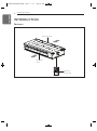
INTRODUCTION
ENGLISH
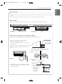
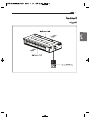
Features
INTRODUCTION
TEMP
FAN
SPEED
OPER
MODE
Remote
Controller
Air inlet vents
Air outlet
vents
1,MFL67939925,영어 2017. 7. 17. 오후 2:33 페이지 6

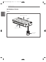
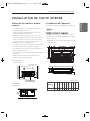
INSTALLATION OF INDOOR
ENGLISH
7
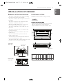
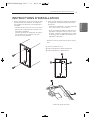
Selection of the best location
- The place shall easily bear a load exceeding
four times the indoor unit’s weight.
- The place shall be able to inspect the unit as
the figure.
- The place where the unit shall be leveled.
- The place shall allow easy water
drainage.(Suitable dimension “H” is neces-
sary to get a slope to drain as figure.)
- The place shall easily connect with the out-
door unit.
- The place where the unit is not affected by
an electrical noise.
- The place where air circulation in the room
will be good .
- There should not be any heat source or
steam near the unit
- Confirm the positional relationship between
the unit and suspension bolts.
- Thermal insulator the ceiling opening to clean
the filter or service under the product.
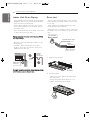
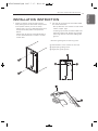
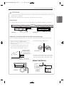
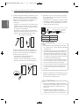
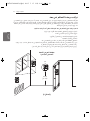
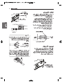
Installation of Unit
Install the unit above the ceiling correctly.
Position of suspension Bolt
- Apply a joint-canvas between the unit and
duct to absorb unnecessary vibration.
- Apply a filter Accessory at air return hole.
CASE 1
INSTALLATION OF INDOOR
Top view
Unit: mm
Front view
Unit: mm
Front
Inspection hole
600 x 600
Control box
1000
20 or more
Air outlet vents
Air inlet vents
600
600
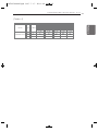
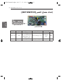
(Unit:mm)
A B C D E F G H I J
Dimension
Capacity
(kw)
Drain hole
A
B
J
CD
E
G
F
I
H
ABNW12GL5S1 933 972 388 460 36 190 20 860 148 900
1,MFL67939925,영어 2017. 7. 17. 오후 2:34 페이지 7

8
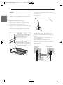
INSTALLATION OF INDOOR
ENGLISH
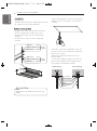
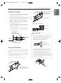
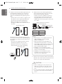
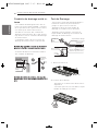
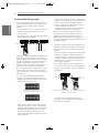
- Install the unit leaning to a drainage hole side
as a figure for easy water drainage.
P
osition of console Bolt
- A place where the unit will be leveled and
that can support the weight of the unit.
- A place where the unit can withstand its
vibration.
- A place where service can be easily per-
formed.
- Select and mark the position for fixing bolts.
- Drill the hole for set anchor on the face of
ceiling.
- Insert the set anchor and washer onto the
suspension bolts for locking the suspension
bolts on the ceiling.
- Mount the suspension bolts to the set
anchor firmly.
- Secure the installation plates onto the sus-
pension bolts (adjust level roughly) using
nuts, washers and spring washers.
CASE 2
1 Set anchor
Old building New building
2 Plate washer
3 Spring washer
4 Nut
5 Suspension
bolts
CAUTION
Tighten the nut and bolt to prevent unit
falling.
!
M10 Nut
M10 SP. washer
M10 washer
X 4
X 4
(Local
supply)
X 4
M10 Nut
M10 SP. washer
M10 washer
X 4
X 4
(Local
supply)
X 4
1,MFL67939925,영어 2017. 7. 17. 오후 2:34 페이지 8

INSTALLATION OF INDOOR
ENGLISH
9
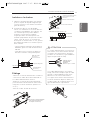
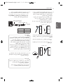
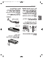
CAUTION
• Install declination of the indoor unit is very important for the drain of the duct type air condi-
tioner.
• Minimum thickness of the insulation for the connecting pipe shall be 5mm.
Front of view
• The unit must be declined to the drain hose connected when finished installation.
!
Drainage hole
U-Trap
B
C
A ≥ 70 mm
B ≥ 2C
C ≥ 2 x SP
SP = External Pressure
(mmAq)
Ex) External Pressure
= 10 mmAq
A ≥ 70 mm
B ≥ 40 mm
C ≥ 20 mm
A
Make sure to be closed.
Unit
Drainage pipe
(Local supply)
Thermal insulator
(Local supply)
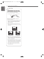
• Always lay the drain with downward
inclination (1/100 to 1/50).
Prevent any upward flow or reverse flow
in any part.
• 10 mm or thicker formed thermal insulator
shall always be provided for the drain
pipe.
• Install the P-Trap (or U-Trap) to prevent
a water leakage caused by the blocking
ofi ntake air filter.
Applied U-Trap Dimension
CORRECT
INCORRECT
• Upward routing not
allowed
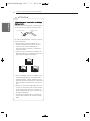
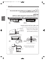
Caution for gradient of unit and drain piping
Lay the drain hose with a downward inclination so water will drain out.
1,MFL67939925,영어 2017. 7. 17. 오후 2:34 페이지 9
Drainage hole
Drainage hole
CORRECT
INCORRECT
1/100~1/50
Ceiling

10
INSTALLATION OF INDOOR
ENGLISH
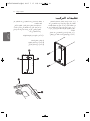
Maintenance
drain port
Upward
routing
not allowed
Pipe clamp
Indoor unit
Indoor Unit Drain Piping
- Drain piping must have down-slope (1/50 to
1/100): be sure not to provide up-and-down
slope to prevent reversal flow.
- During drain piping connection, be careful
not to exert extra force on the drain port on
the indoor unit.
- The outside diameter of the drain connection
on the indoor unit is 32 mm.
Piping material: Polyvinyl chloride pipe VP-25
and pipe fittings
- Be sure to execute thermal insulator on the
drain piping.
- Install the drain raising pipes at a right
angle to the indoor unit and no more than
300 mm from the unit.
T
hermal insulator material: Polyethylene foam
w ith thickness more than 8 mm.
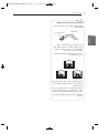
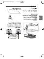
Drain test
- Connect the main drain pipe to the exterior
and leave it provisionally until the test comes
to an end.
- Feed water to the flexible drain hose and
check the piping for leakage.
- When the test is complete, connect the flexi-
ble drain hose to the drain port on the indoor
unit.
1 Remove the air filter.
2 Check the drain.
- Spray one or two glasses of water upon
the evaporator.
- Ensure that water flows drain hose of
indoor unit without any leakage.
Feed water
Flexible drain hose
(accessory)
Main
drain pipe
Glue the join
t
Air filters
1,MFL67939925,영어 2017. 7. 17. 오후 2:34 페이지 10

INSTALLATION OF INDOOR
ENGLISH
11
Thermal insulator
1 Use the thermal insulator material for the
refrigerant piping which has an excellent
heat-resistance (over 120 °C).
2 If this air conditioner is operated for a long
time in high humid atmosphere (dew point
temperature: more than 23 °C), water
drops are liable to fall. In this case, add
thermal insulator material according to the
following procedure:
- Thermal insulation material to be pre-
pared... Adiabatic glass wool with thick-
ness 10 to 20 mm.
- Stick glass wool on all air conditioners
that are located in ceiling atmosphere.
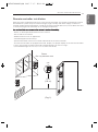
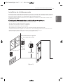
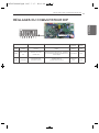
Wiring Connection
- Open the control box cover and connect the
Remote controller cable and Indoor power
wires.
- Remove the control box cover for electrical
connection between the indoor and outdoor
unit. (Remove screws ①.)
- Use the cord clamper to fix the cable.
Control box
Control terminal board
Remote controler cable
Connection cable between
the indoor unit and
the outdoor unit
<Outdoor Unit Power Supply : 1Ø>
Indoor unit
Outdoor unit
POWER SUPPLY
1(L) 2(N) 3
1(L) 2(N) 31(L) 2(N)
CAUTION
• The connecting cable connected to the
indoor and outdoor unit should be com-
plied with the following specifications
(Rubber insulation, type H05RN-F
approved by HAR or SAA).
• If the supply cable is damaged, it must
be replaced by a special cable or assem-
bly available from the manufacturer of
its service agent. When the connection
line between the indoor unit and out-
dooor unit and outdoor unit is over 40 m,
connect the telecommunication line and
power line separately.
!
20 mm
GN/YL
NORMFAL
CROSS-SECTIONAL
AREA :
1 Phase Model : 0.75mm
2
Indoor unit
Thermal insulator
(accessory)
Fastening band
(accessory)
Refrigerant
piping
Control box cover
(On which the Electric
Wiring Connection is put)
1
1
1
1,MFL67939925,영어 2017. 7. 17. 오후 2:34 페이지 11

12
INSTALLATION OF INDOOR
ENGLISH
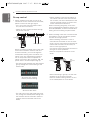
CAUTION
Precautions when laying power wiring
Use round pressure terminals for connec-
tions to the power terminal block.
When none are available, follow the
instructions below.
• Do not connect wiring of different thick-
nesses to the power terminal block.
(Slack in the power wiring may cause
abnormal heat.)
• When connecting wiring which is the
same thickness, do as shown in the fig-
ure below.
• For wiring, use the designated power
wire and connect firmly, then secure to
prevent outside pressure being exerted
on the terminal block.
• Use an appropriate screwdriver for tight-
ening the terinal screws. A screwdriver
with a small head will strip the head and
make proper tighterning impossible.
• Over-tightening the terminal screws
may break them.
!
Round pressure terminal
Power wiring
1,MFL67939925,영어 2017. 7. 17. 오후 2:34 페이지 12

INSTALLATION INSTRUCTION
ENGLISH
13
INSTALLATION INSTRUCTION
1 Please fix tightly using provided screw
after placing remote controller setup board
on the place where you like to setup.
- Please set it up not to bend because poor
setup could take place if setup board
bends.
Please set up remote controller board fit
to the reclamation box if there is a recla-
mation box.
2 Can set up wired remote controller cable
into three directions.
- Set up direction: the surface of wall recla-
mation, upper, right
- If setting up remote controller cable into
upper and right side, please set up after
removing remote controller cable guide
groove.
* Remove guide groove with long nose.
① Reclamation to the surface of the wall
② Upper part guide groove
③ Right part guide groove
1,MFL67939925,영어 2017. 7. 17. 오후 2:34 페이지 13

14
INSTALLATION INSTRUCTION
ENGLISH
CAUTION
• When installing the wired remote con-
troller, do not bury it in the wall. (It can
cause damage in the temperature sen-
sor.)
• Do not install the cable to be 50 m(164 ft)
or longer. (It can cause communication
error.)
!
3 Please fix remote controller upper part into
the backplate attached to the surface of
the wall, as the picture below, and then,
connect with backplate by pressing lower
part.
- Please make sure to leave no gaps on the
top, bottom, left or right sides between
the remote controller and backplate.
- Before assembly with the backplate,
arrange the Cable not to interfere with cir-
cuit parts.
Remove remote controller by inserting a
screwdriver into the lower separating holes
and twisting to release the controller from
backplate.
- There are two separating holes. Please
individually separate one at a time.
- Please be careful not to damage the
inside components when separating.
4 Please refer to the following directions
when connecting the indoor unit and the
wired remote controller together.
- Please connect the cables as shown in
the figure below when connecting the
plug type cable from the indoor unit’s
C/BOX and the housing type of the exten-
sion cable.
5
Please use an extension cable if the distance
between the wired remote controller and the
indoor unit is longer than 10 m(32 ft).
Wall
Side
Wall
Side
<Connecting order>
Please check if the connectors
are connected properly.
C/BOX Cable (Plug type)
Extension cable(housing type)
Indoor
Unit side
TEMP
FAN
SPEED
OPER
MODE
Wall
Side
Wall
Side
<Separating order>
CAUTION
• Specification of LG supplied extension
cable: AWG#22, 3 core shielded.
(Model : PZCWRC1)
* Apply enclosed noncombustible con-
duit(metal raceway) totally or use FT-6
rated cable or above level in case of local
electric & building code that requires
plenum (CMP) cable usage.
• AWG#22, 3 core shielded is recom-
mended when using the large hole in the
center of the back plate.
• AWG#24, 3 core shielded is recom-
mended when using the side or top
knock-out of the back plate.
!
Signal Yellow
12 V Red
GND Black
1,MFL67939925,영어 2017. 7. 17. 오후 2:34 페이지 14

INSTALLATION INSTRUCTION
ENGLISH
15
Remote controller installation
Since the room temperature sensor is in the remote controller, the remote controller box should
be installed in a place away from direct sunlight, high humidity and direct supply of cold air to
maintain proper space temperature. Install the remote controller about 5 ft(1.5 m) above the floor
in an area with good air circulation at an average temperature.
Do not install the remote controller where it can be affected by:
- Drafts, or dead spots behind doors and in corners.
- Hot or cold air from ducts.
- Radiant heat from sun or appliances.
- Concealed pipes and chimneys.
- Uncontrolled areas such as an outside wall behind the remote controller.
- This remote controller is equipped with LCD. display. For proper display of the remote controller
LCD's, the remote controller should be installed properly as shown in Fig.1.
(The standard height is 4~5 ft (1.2~1.5 m) from floor level.)
TEMP
FAN
SPEED
OPER
MODE
TEMP
FAN
SPEED
OPER
MODE
TEMP
FAN
SPEED
OPER
MODE
TEMP
FAN
SPEED
OPER
MODE
5 ft
(1.5 m)
(Fig. 1)
Direct
Sun ray contact area
no
no
no
yes
1,MFL67939925,영어 2017. 7. 17. 오후 2:34 페이지 15

16
INSTALLATION INSTRUCTION
ENGLISH
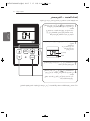
Group control
1 When installing more than 2 units of air
conditioner to one wired remote controller,
please connect as the right figure.
- If it is not event communication indoor
unit, set the unit as slave.
- Check for event communication through
the product manual.
When controlling multiple indoor units with
event communication function with one
remote controller, you must change the
master/slave setting from the indoor unit.
Indoor units, the master/slave configura-
tion of the product after completion of
indoor unit power ‘OFF’ and then ‘ON’ the
power after 1 minutes elapsed sign up.
- For ceiling type cassette and duct product
group, change the switch setting of the
indoor PCB.
- For wall-mount type and stand type prod-
uct, change the master/slave setting with
the wireless remote controller. (Refer to
wireless remote controller manual for
detail)
* When installing 2 remote controllers to
one indoor unit with event communica-
tion function, set the master/slave of the
remote controller. (Refer to remote con-
troller master/slave selection)
When controlling the group, some func-
tions excluding basic operation setting, fan
level Min/Mid/Max, remote controller lock
setting and time setting may be limited.
2 When installing more than 2 wired remote
controllers to one air conditioner, please
connect as the right picture.
- When installing more than 2 units of
wired remote controller to one air condi-
tioner, set one wired remote controller as
master and the others all as slaves, as
shown in the right picture.
- You cannot control the group as shown in
the right for some products.
- Refer to the product manual for more
detail.
- When controlling in groups, set the mas-
ter/slave of the remote controller.
Refer to Installer setting section on how
to set master/slave for more detail.
GND
GND
12V
Signal wire
Signal wire
TEMP
FAN
SPEED
ROOM
TEMP
GND
12V
B Y R B Y R
MASTER SLAVE
Signal wire
GND
12V
Signal wire
TEMP
FAN
SPEED
ROOM
TEMP
TEMP
FAN
SPEED
ROOM
TEMP
#3 switch OFF: Master
(Factory default setting)
#3 switch ON: Slave
1,MFL67939925,영어 2017. 7. 17. 오후 2:34 페이지 16

INSTALLATION INSTRUCTION
ENGLISH
17
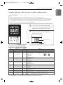
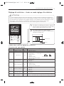
Installer Setting - How to enter installer setting mode
CAUTION
Installer setting mode is to set the detail function of the remote controller.
If the installer setting mode is not set correctly, it can cause problems to the product, user
injury or property damage. This must be set by an certificated installer, and any installation
or change that is carried out by a non-certificated person should be responsible for the
results. In this case, free service cannot be provided.
!
TEMP
FAN
SPEED
OPER
MODE
Function Code
Value
If you want to set installer setting mode,
Press the Temperature up button and the oper
mode button same time for five seconds.
1
When you enter the setting mode
Initially. Function code is displayed
on the LCD screen.
2
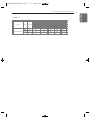
<Installer Setting Code Table>
General air-conditioner product
No. Function Code Value
1 Test Run 01 01:Set
2 Address Setting 02 00~FF : Address
<ESP Step> <ESP Value><Example>
01:VeryLow 0 ~ 255
02:Low
3 E.S.P. Value 03
03:Med
04:High
05:Very High
01:Remo
4 Thermistor 04 02:Indoor
03:2TH
01:Med
02:Low
5 Ceiling Height 05
03:High
04:Very High
01:V-H
02:F-H
6 Static Pressure 06
03:V-L
04:F-L
7 Master Setting 07
00:Slave
01:Master
8
Celsius
12
00:Celsius
(Optimized only for U.S.A)
Fahrenheit Switching 01:Fahrenheit
9
Static Pressure
32
00: use static pressure (code 06) set value
Step 01~ 11: static pressure step (code 32) set value
Function Code ESP valueESP step
* Some contents may not be displayed depending on the product function
1,MFL67939925,영어 2017. 7. 17. 오후 2:34 페이지 17

18
INSTALLATION INSTRUCTION
ENGLISH
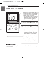
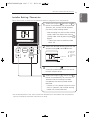
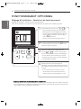
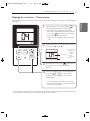
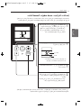
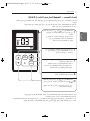
Installer Setting - Test Run Mode
After installing the product, you must run a Test Run mode.
For details related to this operation, refer to the product manual.
TEMP
FAN
SPEED
OPER
MODE
When pressing the button and
button simultaneously for more than 3
seconds, the system will be entered
into the installer setting mode.
- After entering into the installer setting
mode, select the test run mode code
value by pressing the button.
* Test run mode code value : 01
1
When pressing the button, the test
operation mode will be performed, and it
is displayed as shown in the left figure.
2
When pressing the button and
button simultaneously for more than 3
seconds after the setting has been
completed, the setting mode will be
released.
- If there isn’t any button input for
more than 25 seconds, the installer
setting mode will also be released.
3
When approx. 18 minutes are elapsed
after starting of the test oper-mode, the
system will be stopped automatically
and converted to the standby state.
- If any button is inputted during the
test run mode, the test run mode will
be forced to be relreased.
4
OPER
MODE
OPER
MODE
OPER
MODE
OPER
MODE
What is the test run mode?
- This means the operation of the product under the cooling, strong wind, and Comp on state
without performing room temperature control in order to confirm the installed state during the
product installation.
1,MFL67939925,영어 2017. 7. 17. 오후 2:34 페이지 18

INSTALLATION INSTRUCTION
ENGLISH
19
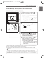
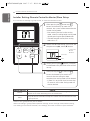
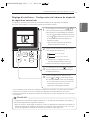
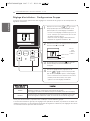
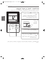
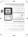
Installer Setting - Setting Address of Central Control
It's the function to use for connecting central control.
Please refer to central controller manual for the details
TEMP
FAN
SPEED
OPER
MODE
When pressing the button and
button simultaneously for more than 3
seconds, the system will be entered into the
installer setting mode.
-
After entering into the installer setting mode,
select the central control address setting
code value by pressing the button.
* Setting address of central control code
value : 02
1
When pressing the button, the system
will be set up with the address value which
has been established at present.
3
When pressing the button and
button simultaneously for more than 3
seconds after the setting has been completed,
the setting mode will be released.
- If there isn’t any button input for more than
25 seconds, the installer setting mode will
also be released.
4
Set up the group number and indoor unit with
the temperature adjustment(▲,▼) buttons.
For example, when setting as
[ Group number=2 Indoor number=3 ]
it will be displayed as shown in the left figure.
2
OPER
MODE
OPER
MODE
TEMP
Group number
Indoor unit number
OPER
MODE
- If you connect the indoor unit to the central controller, you should set the network address of
the indoor unit so that the central controller could recognize it.
- The center-control address is composed of the group number and the indoor-unit number.
NOTE
!
The remote controller displays 'HL' if central controller has locked the remote controller .
In the case when the lock is set up at the central controller, ‘HL’ will be indicated on the dis-
play window of the wired remote controller and the indoor unit will not be controlled by the
remote controller.
1,MFL67939925,영어 2017. 7. 17. 오후 2:34 페이지 19

20
INSTALLATION INSTRUCTION
ENGLISH
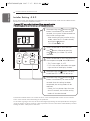
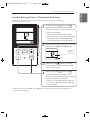
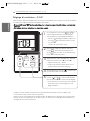
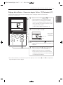
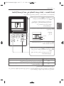
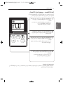
Installer Setting -E.S.P.
This is the function that decides the strength of the wind for each wind level and because this
function is to make the installation easier.
- If you set ESP incorrectly, the air conditioner may malfunction.
- This setting must be carried out by a certificated-technician.
TEMP
FAN
SPEED
OPER
MODE
When pressing the button and
button simultaneously for more than 3
seconds, the system will be entered into
the installer setting mode.
- After entering into the installer setting
mode, select the E.S.P code value by
pressing the button.
* E.S.P code value : 03
1
Select the desired air flow rate with
the button. Whenever pressing
the button, [Lo→Med→Hi] will be
indicated.
2
Select the desired air flow rate value with
the temperature up(▲), down(▼) button.
* E.S.P value range : 0~255
- E.S.P value will be indicated at the upper
right section of the display window.
3
When pressing the button, currently
established E.S.P value will be set up.
4
When pressing the button and
button simultaneously for more than 3
seconds after the setting has been
completed, the setting mode will be
released.
- If there isn’t any button input for more
than 25 seconds, the installer setting
mode will also be released.
5
OPER
MODE
OPER
MODE
FAN
SPEED
FAN
SPEED
OPER
MODE
- Precaution shall be taken not to alter the E.S.P value corresponded to each air flow section.
- E.S.P value can be varied according to the products.
- In the case of going to the next air flow rate stage by pressing the fan-speed button during the
setup of the E.S.P value, the E.S.P value of previous air flow rate will be maintained by remem-
bering the E.S.P value prior to the shift.
1,MFL67939925,영어 2017. 7. 17. 오후 2:34 페이지 20
La page est en cours de chargement...
La page est en cours de chargement...
La page est en cours de chargement...
La page est en cours de chargement...
La page est en cours de chargement...
La page est en cours de chargement...
La page est en cours de chargement...
La page est en cours de chargement...
La page est en cours de chargement...
La page est en cours de chargement...
La page est en cours de chargement...
La page est en cours de chargement...
La page est en cours de chargement...
La page est en cours de chargement...
La page est en cours de chargement...
La page est en cours de chargement...
La page est en cours de chargement...
La page est en cours de chargement...
La page est en cours de chargement...
La page est en cours de chargement...
La page est en cours de chargement...
La page est en cours de chargement...
La page est en cours de chargement...
La page est en cours de chargement...
La page est en cours de chargement...
La page est en cours de chargement...
La page est en cours de chargement...
La page est en cours de chargement...
La page est en cours de chargement...
La page est en cours de chargement...
La page est en cours de chargement...
La page est en cours de chargement...
La page est en cours de chargement...
La page est en cours de chargement...
La page est en cours de chargement...
La page est en cours de chargement...
La page est en cours de chargement...
La page est en cours de chargement...
La page est en cours de chargement...
La page est en cours de chargement...
La page est en cours de chargement...
La page est en cours de chargement...
La page est en cours de chargement...
La page est en cours de chargement...
La page est en cours de chargement...
La page est en cours de chargement...
La page est en cours de chargement...
La page est en cours de chargement...
La page est en cours de chargement...
La page est en cours de chargement...
La page est en cours de chargement...
La page est en cours de chargement...
La page est en cours de chargement...
La page est en cours de chargement...
La page est en cours de chargement...
La page est en cours de chargement...
La page est en cours de chargement...
La page est en cours de chargement...
La page est en cours de chargement...
La page est en cours de chargement...
La page est en cours de chargement...
La page est en cours de chargement...
La page est en cours de chargement...
La page est en cours de chargement...
-
 1
1
-
 2
2
-
 3
3
-
 4
4
-
 5
5
-
 6
6
-
 7
7
-
 8
8
-
 9
9
-
 10
10
-
 11
11
-
 12
12
-
 13
13
-
 14
14
-
 15
15
-
 16
16
-
 17
17
-
 18
18
-
 19
19
-
 20
20
-
 21
21
-
 22
22
-
 23
23
-
 24
24
-
 25
25
-
 26
26
-
 27
27
-
 28
28
-
 29
29
-
 30
30
-
 31
31
-
 32
32
-
 33
33
-
 34
34
-
 35
35
-
 36
36
-
 37
37
-
 38
38
-
 39
39
-
 40
40
-
 41
41
-
 42
42
-
 43
43
-
 44
44
-
 45
45
-
 46
46
-
 47
47
-
 48
48
-
 49
49
-
 50
50
-
 51
51
-
 52
52
-
 53
53
-
 54
54
-
 55
55
-
 56
56
-
 57
57
-
 58
58
-
 59
59
-
 60
60
-
 61
61
-
 62
62
-
 63
63
-
 64
64
-
 65
65
-
 66
66
-
 67
67
-
 68
68
-
 69
69
-
 70
70
-
 71
71
-
 72
72
-
 73
73
-
 74
74
-
 75
75
-
 76
76
-
 77
77
-
 78
78
-
 79
79
-
 80
80
-
 81
81
-
 82
82
-
 83
83
-
 84
84


LG ABNW12GL5S1.ENWTMEA Guide d'installation
- Taper
- Guide d'installation
- Ce manuel convient également à
dans d''autres langues
Documents connexes
-
LG PQRCHCA0QW Le manuel du propriétaire
-
LG PQRCVCL0QW Le manuel du propriétaire
-
LG ABNW50LM3S1.ENWBLMC Guide d'installation
-
-
LG JRNU18GB2G3.APUNEB Le manuel du propriétaire
-
-
-
-
LG ABNW24GM1S1.ENWBMEA Guide d'installation
-