Extron PowerCage 401 FOX DR HD Manuel utilisateur
- Catégorie
- Commutateurs vidéo
- Taper
- Manuel utilisateur
Ce manuel convient également à

User Guide
PowerCage
®
401 FOX DT HD
PowerCage
®
401 FOX DR HD
Fiber Optic Extenders
Dual Fiber Optic Transmitter and Receiver
68-2659-01 Rev. B
01 19

Safety Instructions
Istruzioni di sicurezza • Italiano
AVVISO: Questo simbolo, ,quando viene utilizzato il prodotto, serve ad
avvisare l’utente della presenza di tensioni pericolose non isolate all’interno
del prodotto, che può presentare un rischio di scosse elettriche.
ATTENTZIONE: Questo simbolo, , quando viene utilizzato il prodotto,
serve ad avvisare l’utente di importanti istruzioni di uso e manutenzione
(assistenza) nella letteratura fornita con l’apparecchiatura.
Per informazioni sulle linee guida di sicurezza, adempimenti normativi,
compatibilità EMI/EMF, accessibilità e argomenti correlati, vedere la sicurezza di
Extron e Regulatory Compliance Guide, parte numero 68-290-01, sul sito Web
Extron, www.extron.com.
Instrukcje bezpieczeństwa • Polska
OSTRZEŻENIE: Ten symbol, , gdy używany na produkt, ma na celu
poinformować użytkownika o obecności izolowanego i niebezpiecznego
napięcia wewnątrz obudowy produktu, który może stanowić zagrożenie
porażenia prądem elektrycznym.
UWAGI: Ten symbol, , gdy używany na produkt, jest przeznaczony do
ostrzegania użytkownika ważne operacyjne oraz instrukcje konserwacji
(obsługi) w literaturze, wyposażone w sprzęt.
Informacji na temat wytycznych w sprawie bezpieczeństwa, regulacji wzajemnej
zgodności, zgodność EMI/EMF, dostępności i Tematy pokrewne, zobacz Extron
bezpieczeństwa i regulacyjnego zgodności przewodnik, część numer
68-290-01, na stronie internetowej Extron, www.extron.com.
Инструкция по технике безопасности • Русский
ПРЕДУПРЕЖДЕНИЕ: Данный символ, , если указан
на продукте, предупреждает пользователя о наличии
неизолированного опасного напряжения внутри корпуса
продукта, которое может привести к поражению
электрическим током.
ВНИМАНИЕ: Данный символ, , если указан на продукте,
предупреждает пользователя о наличии важных инструкций
по эксплуатации и обслуживанию в руководстве,
прилагаемом к данному оборудованию.
Для получения информации о правилах техники безопасности,
соблюдении нормативных требований, электромагнитной
совместимости (ЭМП/ЭДС), возможности доступа и других
вопросах см. руководство по безопасности и соблюдению
нормативных требований Extron на сайте Extron: www.extron.com,
номер по каталогу - 68-290-01.
安全说明 • 简体中文
警告: 产品上的这个标志意在警告用户该产品机壳内有暴露的危险 电压,
有触电危险。
注意: 产品上的这个标志意在提示用户设备随附的用户手册中有
重要的操作和维护(维修)说明。
关于我们产品的安全指南、遵循的规范、EMI/EMF 的兼容性、无障碍
使用的特性等相关内容,敬请访问 Extron 网站 www.extron.com,参见
Extron 安全规范指南,产品编号 68-290-01。
Safety Instructions • English
WARNING: This symbol, , when used on the product, is intended to
alert the user of the presence of uninsulated dangerous voltage within the
product’s enclosure that may present a risk of electric shock.
ATTENTION: This symbol, , when used on the product, is intended
to alert the user of important operating and maintenance (servicing)
instructions in the literature provided with the equipment.
For information on safety guidelines, regulatory compliances, EMI/EMF
compatibility, accessibility, and related topics, see the Extron Safety and
Regulatory Compliance Guide, part number 68-290-01, on the Extron website,
www.extron.com.
Sicherheitsanweisungen • Deutsch
WARNUNG: Dieses Symbol auf dem Produkt soll den Benutzer darauf
aufmerksam machen, dass im Inneren des Gehäuses dieses Produktes
gefährliche Spannungen herrschen, die nicht isoliert sind und die einen
elektrischen Schlag verursachen können.
VORSICHT: Dieses Symbol auf dem Produkt soll dem Benutzer in der
im Lieferumfang enthaltenen Dokumentation besonders wichtige Hinweise
zur Bedienung und Wartung (Instandhaltung) geben.
Weitere Informationen über die Sicherheitsrichtlinien, Produkthandhabung,
EMI/EMF-Kompatibilität, Zugänglichkeit und verwandte Themen finden Sie in
den Extron-Richtlinien für Sicherheit und Handhabung (Artikelnummer
68-290-01) auf der Extron-Website, www.extron.com.
Instrucciones de seguridad • Español
ADVERTENCIA: Este símbolo, , cuando se utiliza en el producto,
avisa al usuario de la presencia de voltaje peligroso sin aislar dentro del
producto, lo que puede representar un riesgo de descarga eléctrica.
ATENCIÓN: Este símbolo, , cuando se utiliza en el producto, avisa
al usuario de la presencia de importantes instrucciones de uso y
mantenimiento recogidas en la documentación proporcionada con el
equipo.
Para obtener información sobre directrices de seguridad, cumplimiento
de normativas, compatibilidad electromagnética, accesibilidad y temas
relacionados, consulte la Guía de cumplimiento de normativas y seguridad de
Extron, referencia 68-290-01, en el sitio Web de Extron, www.extron.com.
Instructions de sécurité • Français
AVERTISSEMENT : Ce pictogramme, , lorsqu’il est utilisé sur le
produit, signale à l’utilisateur la présence à l’intérieur du boîtier du produit
d’une tension électrique dangereuse susceptible de provoquer un choc
électrique.
ATTENTION : Ce pictogramme, , lorsqu’il est utilisé sur le produit, signale
à l’utilisateur des instructions d’utilisation ou de maintenance importantes
qui se trouvent dans la documentation fournie avec le matériel.
Pour en savoir plus sur les règles de sécurité, la conformité à la réglementation,
la compatibilité EMI/EMF, l’accessibilité, et autres sujets connexes, lisez les
informations de sécurité et de conformité Extron, réf. 68-290-01, sur le site
Extron, www.extron.com.

安全記事 • 繁體中文
警告: 若產品上使用此符號,是為了提醒使用者,產品機殼內存在著
可能會導致觸電之風險的未絕緣危險電壓。
注意: 若產品上使用此符號,是為了提醒使用者,設備隨附的用戶手冊中有重
要的操作和維護(維修)説明。
有關安全性指導方針、法規遵守、EMI/EMF 相容性、存取範圍和相關主題的詳細資
訊,請瀏覽 Extron 網站:www.extron.com,然後參閱《Extron 安全性與法規
遵守手冊》,準則編號 68-290-01。
安全上のご注意
• 日本語
警告: この記号 が製品上に表示されている場合は、筐体内に絶縁されて
いない高電圧が流れ、感電の危険があることを示しています。
注意: この記号 が製品上に表示されている場合は、本機の取扱説明書
に 記載されている重要な操作と保守(整備)の指示についてユーザーの
注 意を 喚 起 するも ので す。
安全上のご注意、法規厳守、EMI/EMF適合性、その他の関連項目に
つ いて は、エクストロン のウェブ サイト www.extron.com よ り 『 Extron Safety
and Regulatory Compliance Guide』 (P/N 68-290-01) をご覧ください 。
안전 지침 • 한국어
경고: 이 기호 가 제품에 사용될 경우, 제품의 인클로저 내에 있는
접지되지 않은 위험한 전류로 인해 사용자가 감전될 위험이 있음을
경고합니다.
주의: 이 기호 가 제품에 사용될 경우, 장비와 함께 제공된 책자에 나와
있는 주요 운영 및 유지보수(정비) 지침을 경고합니다.
안전 가이드라인, 규제 준수, EMI/EMF 호환성, 접근성, 그리고 관련 항목에
대한 자세한 내용은 Extron 웹 사이트(www.extron.com)의 Extron 안전 및
규제 준수 안내서, 68-290-01 조항을 참조하십시오.
Copyright
© 2019 Extron Electronics. All rights reserved.
Trademarks
All trademarks mentioned in this guide are the properties of their respective owners.
The following registered Trademarks (
®
), registered service Marks (
SM
), and Trademarks (™) are the property of RGBSystems, Inc. or
Extron Electronics (see the current list of trademarks on the Terms of Use page at www.extron.com):
Registered Trademarks
(®)
Extron, AVTrac, Cable Cubby, CrossPoint, DTP, eBUS, EDID Manager, EDID Minder, Flat Field, FlexOS, Global Configurator, Global Scripter,
GlobalViewer, Hideaway, Inline, IPIntercom, IPLink, KeyMinder, LinkLicense, LockIt, MediaLink, MediaPort, NetPA, PlenumVault, PoleVault,
PowerCage, PURE3, Quantum, SoundField, SpeedMount, SpeedSwitch, SystemINTEGRATOR, TeamWork, TouchLink, V-Lock, VersaTools,
VN-Matrix, VoiceLift, WallVault, WindoWall, XTP, and XTPSystems
Registered Service Mark
(SM)
: S3 Service Support Solutions
Trademarks
(
™
)
AAP, AFL (Accu-RateFrameLock), ADSP(Advanced Digital Sync Processing), Auto-Image, CableCover, CDRS(ClassDRippleSuppression),
DDSP(Digital Display Sync Processing), DMI (DynamicMotionInterpolation), DriverConfigurator, DSPConfigurator, DSVP(Digital Sync Validation
Processing), eLink, EQIP, FastBite, FOX, FOXBOX, IP Intercom HelpDesk, MAAP, MicroDigital, ProDSP, QS-FPC(QuickSwitch Front Panel Controller),
Room Agent, Scope-Trigger, ShareLink, SIS, SimpleInstructionSet, Skew-Free, SpeedNav, Triple-Action Switching, True4K, Vector™ 4K, WebShare,
XTRA, ZipCaddy, ZipClip

FCC Class A Notice
This equipment has been tested and found to comply with the limits for a Class A digital
device, pursuant to part15 of the FCC rules. The ClassA limits provide reasonable
protection against harmful interference when the equipment is operated in a commercial
environment. This equipment generates, uses, and can radiate radio frequency energy and,
if not installed and used in accordance with the instruction manual, may cause harmful
interference to radio communications. Operation of this equipment in a residential area is
likely to cause interference. This interference must be corrected at the expense of the user.
Class 1 Laser Product
Any service to this product must be carried out by Extron Electronics and its qualified
service personnel.
CAUTION: Using controls, making adjustments, or performing procedures in a manner
other than what is specified herein may result in hazardous radiation exposure.
NOTE: For more information on safety guidelines, regulatory compliances, EMI/EMF
compatibility, accessibility, and related topics, see the “Extron Safety and
Regulatory Compliance Guide” on the Extron website.
Produit laser de classe1
Si ce produit a besoin d’un quelconque entretient, celui-ci doit être fait par
ExtronElectronics et son personnel qualifié.
ATTENTION : L’utilisation de commandes, la réalisation de réglages, ou l’exécution de
procédures de manière contraire aux dispositions établies dans le présent document,
présente un risque d’exposition dangereuse aux radiations.
Remarque: Pour plus d'informations sur les directives de sécurité, les conformités de
régulation, la compatibilité EMI/EMF, l'accessibilité, et les sujets en lien, consultez le
«Informations de sécurité et de conformité Extron» sur le site internet d'Extron.

Conventions Used in this Guide
Notifications
The following notifications are used in this guide:
WARNING: Potential risk of severe injury or death.
AVERTISSEMENT: Risque potentiel de blessure grave ou de mort.
CAUTION: Risk of minor personal injury.
ATTENTION : Risque de blessuremineure.
ATTENTION:
• Risk of property damage.
• Risque de dommages matériels.
NOTE: A note draws attention to important information.
TIP: A tip provides a suggestion to make working with the application easier.
Software Commands
Commands are written in the fonts shown here:
^AR Merge Scene,,Op1 scene 1,1 ^B 51 ^W^C
[01] R 0004 00300 00400 00800 00600 [02] 35 [17] [03]
EX!*X1&*X2)*X2#*X2!CE}
NOTE: For commands and examples of computer or device responses mentioned
in this guide, the character “0” is used for the number zero and “O” is the capital
letter “o.”
Computer responses and directory paths that do not have variables are written in the font
shown here:
Reply from 208.132.180.48: bytes=32 times=2ms TTL=32
C:\Program Files\Extron
Variables are written in slanted form as shown here:
ping xxx.xxx.xxx.xxx —t
SOH R Data STX Command ETB ETX
Selectable items, such as menu names, menu options, buttons, tabs, and field names are
written in the font shown here:
From the File menu, select New.
Click the OK button.
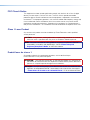
Specifications Availability
Product specifications are available on the Extron website, www.extron.com.
Extron Glossary of Terms
A glossary of terms is available at http://www.extron.com/technology/glossary.aspx.


viiPowerCage 401 Dual Fiber Optic Boards • Contents
Contents
Introduction ...............................................1
Guide Overview ................................................... 1
Product Description ............................................. 1
System Compatibility ....................................... 3
Cable Transmission Modes .............................. 3
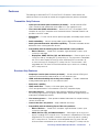
Features .............................................................. 4
Transmitter Only Features ................................ 4
Receiver Only Features .................................... 4
General Features ............................................. 5
Control Methods .................................................. 5
Installation ................................................. 6
PowerCage Installation ........................................ 6
Panel Features ..................................................... 7
Connection Details .............................................. 9
HDMI Connection ............................................ 9
Analog Audio Connection .............................. 10
Daisy Chain ................................................... 10
RS-232 Connection ....................................... 11
Operation .......................................................... 11
Enclosure Menu System ..........................12
Menu Overview .................................................. 12
Menu Access ................................................. 13
Menu Navigation ............................................ 13
Transmitter Menu ............................................... 14
Transmitter Model Name Submenu ................ 14
Transmitter Part Number and Firmware
Version Submenu ......................................... 14
EDID Submenu .............................................. 15
HDCP Authorized Submenu .......................... 16
Audio Selection Submenu.............................. 16
Audio Gain and Attenuation Submenu ........... 16
Transmitter RS-232 Insertion Submenu ......... 16
Input Detection Submenu .............................. 17
Input HDCP Submenu ................................... 17
Audio Input Submenu .................................... 17
Transmitter SFP Rx Alarm Submenu .............. 17
Transmitter Temperature Submenu ................ 17
Transmitter Factory Reset Submenus ............ 17
Receiver Menu .................................................. 18
Receiver Model Name Submenu ................... 18
Receiver Part Number and Firmware
Version Submenu ......................................... 18
Video Mute Submenu .................................... 19
Audio Mute Submenu .................................... 19
HDCP Mode Submenu .................................. 19
HDCP Notification Submenu .......................... 19
Horizontal Shift Submenu .............................. 19
Vertical Shift Submenu ................................... 19
Receiver RS-232 Insertion Submenu ............. 20
Save Presets Submenu ................................. 20
Recall Presets Submenu ................................ 20
Auto Memory Submenu ................................. 20
Test Pattern Submenu ................................... 20
Receiver SFP Rx Alarm Submenu .................. 21
Receiver Temperature Submenu .................... 21
Receiver Factory Reset Submenus ................ 21
SIS Configuration and Control .................22
Host and Device Communication ...................... 22
Copyright Information .................................... 22
Password Information .................................... 22
Unsolicited Messages .................................... 23
Error Responses ............................................ 23
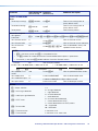
SIS Command and Response Format ........... 23
SIS Overview ..................................................... 24
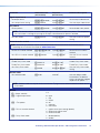
Command and Response Table Overview...... 24
Symbol Definitions ......................................... 24
Command and Response Tables for
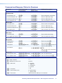
Transmitters ...................................................... 27
EDID Commands ........................................... 27
Audio Configuration Commands .................... 27
Advanced Configuration Commands ............. 28
Device Commands ........................................ 29

PowerCage 401 Dual Fiber Optic Boards • Contents viii
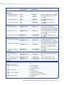
Command and Response Tables for
Receivers ......................................................... 31
Picture Control Commands............................ 31
Audio Configuration Commands .................... 31
Preset Commands ......................................... 31
Advanced Configuration Commands ............. 32
Device Commands ........................................ 34
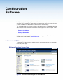
Configuration Software ............................36
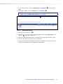
Software Installation........................................... 36
Software Download Center Page ................... 36
PCS Product Page ........................................ 38
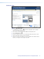
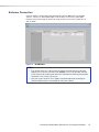
Software Connection ......................................... 39
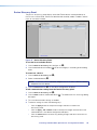
Device Discovery Panel .................................. 40
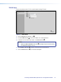
TCP/IP Panel ................................................. 41
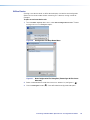
Offline Device ................................................. 42
Help File Access ................................................ 43
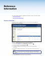
Reference Information ............................. 44
Firmware Download ........................................... 44
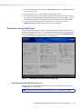
Enclosure Internal Web Page ............................. 45
Enclosure Internal Web Page Access ............. 45
Firmware Updates through the Enclosure
Internal Web Page ........................................ 46

PowerCage 401 Dual Fiber Optic Boards • Introduction 1
Introduction
This section contains basic information about this guide and the Extron
PowerCage 401 FOX DT HD Transmitter and PowerCage 401 FOX DR HD Receiver. Topics
in this section include the following:
• Guide Overview
• Product Description
• Features
• Control Methods
Guide Overview
This guide contains information regarding the installation, configuration, and control of the
PowerCage 401 FOX DT HD Transmitter and PowerCage 401 FOX DR HD Receiver. In this
guide, the following terms are used:
• The terms “FOX DT HD” and “transmitter” refer to any model of the PowerCage 401
FOX DT HD Transmitter.
• The terms “FOX DR HD” and “receiver” refer to any model of the PowerCage 401
FOX DR HD Receiver.
• The term “boards” refers to any PowerCage 401 FOX DT HD Transmitter or
PowerCage 401 FOX DR HD Receiver model.
• The terms “PowerCage 401” and “enclosure” refer to the PowerCage 401 Modular
Power Enclosure for Fiber Optic Extenders.
Product Description
Both the FOX DT HD and FOX DR HD are modular boards designed for a single slot in the
PowerCage 401 enclosure. They are hot-swappable and provide HDMI video, audio, and
control signal extension over fiber optic cables. The FOX DT HD includes two independent
FOX Series transmitters. The FOX DR HD includes two independent FOX Series receivers.
WARNING: Potential risk of severe injury. The FOX DT HD and FOX DR HD output
continuous invisible light, which may be harmful to the eyes; use with caution.
AVERTISSEMENT: Risque potentiel de blessure grave ou de mort. Le
FOX DT HD et FOX DR HD émet une lumière invisible en continu qui peut être
dangereux pour les yeux, à utiliser avec précaution.
• Do not look into the rear panel fiber optic cable connectors or into the fiber optic
cables themselves.
• Ne regardez pas dans les connecteurs de câble fibre optique sur le panneau arrière
ou dans les câbles fibre optique eux-mêmes.
• Plug the attached dust caps into the optical transceivers when the fiber cable is
unplugged.
• Branchez les protections contre la poussière dans l’ensemble émetteur/récepteur
lorsque le câble fibre optique est débranché.

PowerCage 401 Dual Fiber Optic Boards • Introduction 2
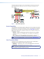
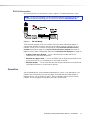
The PowerCage 401 dual fiber optic boards are compatible with FOX II and FOX Series
DisplayPort, HDMI, DVI, and VGA receivers. They can be used in point-to-point applications
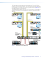
or in combination with FOX Series matrix switchers. See figure 1 below and figure 2 on the
next page for diagrams of typical applications.
The following application diagram shows two FOX DT HD transmitters in a PowerCage 401
enclosure. Each transmitter is connected directly to a receiver for a typical point-to-point
application.
2
RS-232
HDMI
1
AUDIOAUDIO HDMI
FOX DT HD
Tx
Rx
RxTx RxTx
SIGNAL
HDCP
Rx GTx
RS-232
Rx GTx
SIGNAL
HDCP
OPTICALOPTICAL
INPUTS
Tx
Rx
2
RS-232
HDMI
1
AUDIOAUDIO HDMI
FOX DT HD
Tx
Rx
RxTx RxTx
SIGNAL
HDCP
Rx GTx
RS-232
Rx GTx
SIGNAL
HDCP
OPTICAL OPTICAL
INPUTS
Tx
Rx
RS-232
12
FOX DT HD
Tx
Rx
SIGNAL
HDCP
Rx GTx
RS-232
Rx GTx
Tx
Rx
SIGNAL
HDCP
RS-232
HDMI OUT
12
AUDIO OUT AUDIO OUT HDMI OUT
FOX DT HD
Tx
Rx
SIGNAL
HDCP
Rx GTx
RS-232
Rx GTx
Tx
Rx
SIGNAL
HDCP
RS-232
LAN
Rx GTx
REMOTE
100-240V ~ --A MAX100-240V ~ --A MAX
50-60 Hz 50-60 Hz
2
RS-232
HDMI
1
AUDIOAUDIO HDMI
FOX DT HD
Tx
Rx
RxTx RxTx
SIGNAL
HDCP
Rx GTx
RS-232
Rx GTx
SIGNAL
HDCP
OPTICALOPTICAL
INPUTS
2
Tx
Rx
2
RS-232
HDMI
1
AUDIOAUDIO HDMI
FOX DT HD
Tx
Rx
RxTx RxTx
SIGNAL
HDCP
Rx GTx
RS-232
Rx GTx
SIGNAL
HDCP
OPTICAL OPTICAL
INPUTS
2
Tx
Rx
FOXBOX SR HDMI
LINK
LINK
OPTICAL
RxTx
HDMI
AUDIO
OUTPUTS
REMOTE
RS-232
Tx Rx
RS-232
OVER FIBER
ALARM
Tx Rx 1 2
POWER
12V
1.0 A MAX LR
OFF
ON
HDMI AUDIO
FOXBOX SR HDMI
LINK
LINK
OPTICAL
RxTx
HDMI
AUDIO
OUTPUTS
REMOTE
RS-232
Tx Rx
RS-232
OVER FIBER
ALARM
Tx Rx 1 2
POWER
12V
1.0 A MAX
LR
OFF
ON
HDMI AUDIO
FOXBOX SR HDMI
LINK
LINK
OPTICAL
RxTx
HDMI
AUDIO
OUTPUTS
REMOTE
RS-232
Tx Rx
RS-232
OVER FIBER
ALARM
Tx Rx 1 2
POWER
12V
1.0 A MAX LR
OFF
ON
HDMI AUDIO
FOXBOX SR HDMI
LINK
LINK
OPTICAL
RxTx
HDMI
AUDIO
OUTPUTS
REMOTE
RS-232
Tx Rx
RS-232
OVER FIBER
ALARM
Tx Rx 1 2
POWER
12V
1.0 A MAX
LR
OFF
ON
HDMI AUDIO
eBUS
FLEX I/O
RELAYSIR/SERIALCOM
12 VDC
LAN
+V
Tx Rx GTxRxGTx Rx GTxRxG SG SG SG SGRTSCTS
+- +-
+- +-
-S G
PWR OUT = 12W
+S
SGSG SG SGTx Rx GTxRxGTx Rx GTxRxGRTSCTS
1 2 3 4 G
12 34
56 78
1
12 34
56 78
2 3 7
4 5 6 8
1 2
3
100-240V ~ 50-60Hz
5A MAX
SWITCHED 12 VDC
40W MAX TOTAL
4
IPCP PRO 550
PUSH PUSH
POWER GUIDE MENU RES 480 480p 720p 1080i 1080p
DIRECTV HD
SELECT
DIRECTV
PUSH PUSH
POWER GUIDE MENU RES 480 480p 720p 1080i 1080p
DIRECTV HD
SELECT
DIRECTV
PUSH PUSH
POWER GUIDE MENU RES480 480p 720p 1080i1080p
DIRECTV HD
SELECT
DIRECTV
PUSH PUSH
POWER GUIDE MENU RES480 480p 720p 1080i1080p
DIRECTV HD
SELECT
DIRECTV
MODEL 80
FLAT PANEL
MODEL 80
FLAT PANEL
MODEL 80
FLAT PANEL
MODEL 80
FLAT PANEL
Help
System
Off
Display
Room
Control
Off
Mute
Screen
Lighting
December 15, 2013 - 7:58 AM
Audio
Control
Volume
Mute
Tuner
1 2 3
VCRLaptop PC DVD
Doc
Cam
Tuner
On
Channel
Last
Presets
More
Presets
321
654
987
Enter
0
HDMI
CATV/Satellite Tuners
Display
HDMI
HDMI
Ethernet
Ethernet
Ethernet
RS-232
RS-232
RS-232
RS-232
Up to 30 km (18.75 miles)
over singlemode ber
SM model
Up to 30 km (18.75 miles)
over singlemode ber
SM model
HDMI
FiberFiber
FiberFiber
HDMI
HDMI
Extron
FOXBOX SR HDMI
Scaling Receiver
Extron
FOXBOX SR HDMI
Scaling Receiver
Extron
PowerCage 401
FOX DT HD
Fiber Optic Transmitter
(2 Slots)
Ext
ron
FO
XBOX SR HDMI
Scalin
g Receiver
Ext
ron
FO
XBOX SR HDMI
Scalin
g Receiver
Display
Display
Display
Extron
IPCP Pro 550
IP Link Pro Control Processor
Extron
TLP Pro 1020T
10" Tabletop
TouchLink Pro
Touchpanel
TCP/IP
Network
Extron
PowerCage 401
Modular Power Enclosure
for Fiber Optic Extenders
HDMI HDMI
Figure 1. Typical Point-to-Point Application

PowerCage 401 Dual Fiber Optic Boards • Introduction 3
The following application diagram shows two PowerCage 401 enclosures (one with three
FOX DT HD transmitters and one with two FOX DR HD receivers) connected to a FOX
matrix switcher.
2
RS-232
HDMI
1
AUDIO AUDIO HDMI
FOX DT HD
Tx
Rx
RxTx RxTx
SIGNAL
HDCP
Rx GTx
RS-232
Rx GTx
SIGNAL
HDCP
OPTICALOPTICAL
INPUTS
Tx
Rx
2
RS-232
HDMI
1
AUDIOAUDIO HDMI
FOX DT HD
Tx
Rx
RxTx RxTx
SIGNAL
HDCP
Rx GTx
RS-232
Rx GTx
SIGNAL
HDCP
OPTICALOPTICAL
INPUTS
Tx
Rx
RS-232
12
FOX DT HD
Tx
Rx
SIGNAL
HDCP
Rx GTx
RS-232
Rx GTx
Tx
Rx
SIGNAL
HDCP
RS-232
HDMI OUT
12
AUDIO OUT AUDIO OUT HDMI OUT
FOX DT HD
Tx
Rx
SIGNAL
HDCP
Rx GTx
RS-232
Rx GTx
Tx
Rx
SIGNAL
HDCP
RS-232
LAN
Rx GTx
REMOTE
100-240V ~ --A MAX100-240V ~ --A MAX
50-60 Hz 50-60 Hz
2
RS-232
HDMI
1
AUDIO AUDIO HDMI
FOX DT HD
Tx
Rx
RxTx RxTx
SIGNAL
HDCP
Rx GTx
RS-232
Rx GTx
SIGNAL
HDCP
OPTICALOPTICAL
INPUTS
2
Tx
Rx
2
RS-232
HDMI
1
AUDIO AUDIO HDMI
FOX DT HD
Tx
Rx
RxTx RxTx
SIGNAL
HDCP
Rx GTx
RS-232
Rx GTx
SIGNAL
HDCP
OPTICALOPTICAL
INPUTS
2
Tx
Rx
2
RS-232
HDMI
1
AUDIO AUDIO HDMI
FOX DT HD
Tx
Rx
RxTx RxTx
SIGNAL
HDCP
Rx GTx
RS-232
Rx GTx
SIGNAL
HDCP
OPTICALOPTICAL
INPUTS
2
Tx
Rx
2
RS-232
HDMI
1
AUDIOAUDIO HDMI
FOX DT HD
Tx
Rx
RxTx RxTx
SIGNAL
HDCP
Rx GTx
RS-232
Rx GTx
SIGNAL
HDCP
OPTICALOPTICAL
INPUTS
Tx
Rx
2
RS-232
HDMI
1
AUDIOAUDIOHDMI
FOX DT HD
Tx
Rx
RxTx RxTx
SIGNAL
HDCP
Rx GTx
RS-232
Rx GTx
SIGNAL
HDCP
OPTICALOPTICAL
INPUTS
Tx
Rx
RS-232
12
FOX DT HD
Tx
Rx
SIGNAL
HDCP
Rx GTx
RS-232
Rx GTx
Tx
Rx
SIGNAL
HDCP
RS-232
HDMI OUT
12
AUDIO OUTAUDIO OUT HDMI OUT
FOX DT HD
Tx
Rx
SIGNAL
HDCP
Rx GTx
RS-232
Rx GTx
Tx
Rx
SIGNAL
HDCP
RS-232
LAN
Rx GTx
REMOTE
100-240V ~ --A MAX100-240V ~ --A MAX
50-60 Hz 50-60 Hz
2
RS-232
HDMI
1
AUDIO AUDIO HDMI
FOX DR HD
Tx
Rx
RxTx RxTx
SIGNAL
HDCP
Rx GTx
RS-232
Rx GTx
SIGNAL
HDCP
OPTICALOPTICAL
INPUTS
2
Tx
Rx
2
RS-232
HDMI
1
AUDIO AUDIO HDMI
FOX DR HD
Tx
Rx
RxTx RxTx
SIGNAL
HDCP
Rx GTx
RS-232
Rx GTx
SIGNAL
HDCP
OPTICALOPTICAL
INPUTS
2
Tx
Rx
FOX MATRIX 3200
FIBER OPTIC DIGITAL MATRIX SWITCHER
POWER SUPPLY
PRIMARY
REDUNDANT
INPUTS
OUTPUTS
CONTROL
CONFIG
ENTER PRESET
VIEW
ESC
1
2
3 4
5
6 7 8
9
10
11 12
13 14 15 16
17
18
19 20
21
22
23 24
25
26
27
28
29 30 31 32
1
2
3 4
5
6
7
8
9
10
11
12
13 14 15 16
17
18
19
20
21
22
23 24
25
26
27
28
29 30 31 32
PUSH PUSH
POWER GUIDE MENU RES 480 480p720p 1080i 1080p
DIRECTV HD
SELECT
DIRECTV
PUSH PUSH
POWER GUIDE MENU RES 480 480p720p 1080i 1080p
DIRECTV HD
SELECT
DIRECTV
Extron
FOX Matrix 3200
Ext
ron
Powe
rCage
4
01 FOX
DT
HD
Fibe
r Optic
T
ransmitters
(3 s
lots)
CATV/Satellite
Receivers
Extron
PowerCage
401
Extron
PowerCage 401
Fiber
Fiber
PC
DisplayDisplay DisplayDisplay
HDMI
HDMI
HDMI
Up to 30 km
(18.75 miles)
over singlemode
ber SM model
PC
PCPC
Extron
PowerCage 401
FOX DR HD
Fiber Optic Receive
rs
(2 slots)
Figure 2. Typical Matrix Application
System Compatibility
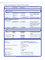
The PowerCage 401 dual fiber optic boards support plus or non-plus mode transmission for
compatibility with FOX transmitters and receivers. Devices in plus mode are only compatible
with other devices in plus mode. Use SIS commands (see the Plus mode commands on
page 28) or the Extron Product Configuration Software (PCS) to change the mode (see the
PowerCage 401 Help file).
• Non-plus — Supports resolutions from 640x480 to 1600x1200 @ 60 Hz, including
480p up to 1080p @ 60 Hz. Embedded audio is not supported, but analog audio is
supported.
• Plus — Supports all resolutions supported in non-plus mode, plus 1920x1200 and
2K (2048x1080) @ 60 Hz. Embedded audio and analog audio are supported.
NOTE: For a list of compatible products, see the Extron website, www.extron.com.
Cable Transmission Modes
The boards are further categorized by the type of fiber optic cable, multimode (MM) or
singlemode (SM), which define the effective range of transmission.
• Multimode — Long distance, up to 2 km (6,560 feet) (depending on the fiber cable)
• Singlemode — Very long distance, up to 30 km (18.75 miles)
NOTE: Multimode and singlemode boards are physically and functionally identical, with
the exception of the effective range of transmission.

PowerCage 401 Dual Fiber Optic Boards • Introduction 4
Features
The following lists describe FOX DT HD and FOX DR HD features. Some features are
specific to either the transmitter or receiver, but the general features pertain to all boards.
Transmitter Only Features
• Inputs per transmitter (two transmitters per board) — Include a female HDMI
type-A connector and unbalanced stereo audio on 3.5 mm stereo mini-jack.
• User-selectable HDCP authorization — Allows the FOX DT HD to appear HDCP
compliant or non-HDCP compliant to the connected source. Protected material is not
passed in non-HDCP mode.
• EDID Minder — Ensures that all sources power up properly and reliably output content
for display.
• Audio embedding — Converts analog audio signals to digital HDMI audio.
• Audio gain and attenuation adjustment capability — Eliminates noticeable volume
differences when switching between sources.
• Compatibility with the following Extron FOX and FOX II series products:
• Matrix switchers — Create HDCP-compliant signal distribution systems up to
1000x1000 and larger.
• DisplayPort, HDMI, DVI Plus, DVI, and VGA receivers — Receive signals up to
1920x1200 and 2K, including HDTV 1080p @ 60 Hz. The transmitter is compatible
with FOX II series DisplayPort and FOX series HDMI and DVI Plus receivers up
to 1920x1200 and 2K, including HDTV 1080p @ 60 Hz. The transmitter is also
compatible with FOX series DVI and VGA receivers up to 1600x1200, including
HDTV 1080p at 60 Hz.
Receiver Only Features
• Outputs per receiver (two receivers per board) — Include a female HDMI type A
connector and unbalanced stereo audio on 3.5 mm stereo mini jack.
• HDMI audio de-embedding with analog stereo outputs — Provides unbalanced
analog stereo audio signals on 3.5 mm stereo mini jacks.
• Audio mute capability
• HDCP notification — Displays a full-screen green signal when
HDCP-encrypted content is transmitted to a non-HDCP compliant display.
• Auto input memory — Automatically stores position and detail settings based on
the incoming signal. When that signal is detected again, the proper image settings are
automatically recalled from memory.
• User memory presets — Saves position and detail information for multiple incoming
sources for recall later.
• Internal color bars test pattern — Helps calibration and setup.
• Compatibility with the following Extron FOX series products:
• Matrix switchers — Create HDCP-compliant signal distribution systems up to
1000x1000 and larger.
• HDMI, DVI Plus, DVI, and VGA transmitters — Send signals up to 1920x1200
and 2K, including HDTV 1080p @ 60 Hz. The receiver is compatible with FOX series
HDMI and DVI Plus transmitters or receivers up to 1920x1200 and 2K, including
HDTV 1080p @ 60 Hz. The receiver is also compatible with FOX series DVI and
VGA transmitters and receivers up to 1600x1200, including HDTV 1080p at 60 Hz.

PowerCage 401 Dual Fiber Optic Boards • Introduction 5
General Features
• Long distance transmission — Transmits or receives HDMI, stereo audio, and
RS-232 control signals very long distances over fiber optic cabling.
• HDCP compliance
• All-digital technology — Provides pixel-for-pixel performance with signals up to
1920x1200, including 1080p/60.
• Key Minder — Authenticates and maintains continuous HDCP encryption between
input and output devices to ensure quick and reliable switching in professional AV
environments, while enabling simultaneous distribution of a single source to multiple
displays.
• Modular, hot-swappable boards designed for the PowerCage 401 enclosure —
Allow the user to replace boards at any time without the need to power down the
system.
• RS-232 insertion from the Ethernet port on the PowerCage 401 enclosure —
Provides system level device control to a local or remote device via the enclosure
Ethernet port without needing additional cabling.
• Space-saving design — Allows up to four boards to be installed in the
PowerCage 401 enclosure, enabling up to eight extenders in a 1U rack space. The
PowerCage 401 eliminates individual power supplies for each board and provides
forced-air cooling for each module.
• Multimode and singlemode availability — Includes an 850 nm multimode model for
long-range transmissions up to 2 km (1.25 miles) and a 1310 nm singlemode model for
extreme distances up to 30 km (18.75 miles).
• Industry standard LC connectors — Provide reliable physical connectivity and
precise fiber core alignment.
• Real-time status LED indicators — Provide visual confirmation of signal presence,
HDCP authentication, link status, and power.
• Alarm notification — Triggers an external control system for immediate notification
when a fiber link has been lost.
• Product Configuration Software — Configures multiple products using a single
software application.
• Includes LockIt HDMI Cable Lacing Brackets
Control Methods
To configure and control the enclosure, transmitter, or receiver, use one of the following
methods:
• Enclosure menu system (see Enclosure Menu System on page 12)
• SIS commands (see SIS Configuration and Control on page 22)
• Extron Product Configuration Software (see Configuration Software on page 36)
NOTE: To configure and control the enclosure, see the PowerCage 401 Enclosure User
Guide at www.extron.com.

PowerCage 401 Dual Fiber Optic Boards • Installation 6
Installation
This section contains installation details. Topics in this section include the following:
• PowerCage Installation
• Panel Features
• Connection Details
• Operation
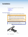
PowerCage Installation
Before connecting devices to PowerCage 401 dual fiber optic boards, install them in a
PowerCage 401 enclosure. They occupy a single slot on a PowerCage 401 enclosure.
ATTENTION:
• Use ESD precautions when installing a board to avoid damaging it. Keep the board
in the anti-static bag until it is needed. Use proper grounding techniques during
installation.
• Prenez les précautions ESD lorsque vous installez une carte afin d’éviter de
l’endommager. Gardez la carte dans le sachet dépoussiérant jusqu’à ce que
vous en ayez besoin. Utilisez des techniques de mise à la terre correctes pendant
l’installation.
• User proper grounding techniques during installation.
• Utilisez des techniques de mise à la terre correctes pendant l’installation.
NOTES:
• PowerCage 401 dual fiber optic boards are hot-swappable.
• Each slot is independent from other slots. The type of board installed in a slot or the
order of slots filled does not impact boards installed in other slots.
RS-232
LAN
Rx GTx
REMOTE
RS-232
HDMI IN
1 2
AUDIO IN AUDIO IN HDMI IN
FOX DT HD
Tx
Rx
SIGNAL
HDCP
Rx GTx
RS-232
Rx GTx
Tx
Rx
SIGNAL
HDCP
RS-232
HDMI IN
1 2
AUDIO IN
AUDIO IN
HDMI IN
FOX DT HD
Tx
Rx
SIGNAL
H
DCP
Rx
GTx
RS-232
Rx GTx
Tx
Rx
SIGNAL
HDCP
2
U
DIO IN
AUDIO IN HDMI IN
FOX DT HD
RS-232
Rx
GTx
Tx
Rx
SIGNAL
HDCP
RS-232
HDMI IN
1 2
AUDIO IN AUDIO IN
HDMI IN
FOX DT HD
Tx
Rx
SIGNAL
HDCP
Rx GTx
RS-232
Rx GTx
Tx
Rx
SIGNAL
HDCP
Screws
(2 per board)
Align board and
slide into slot.
Figure 3. Board Installation

PowerCage 401 Dual Fiber Optic Boards • Installation 7
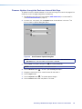
1. If any blank plates or installed boards obstruct the installation of the new board, loosen
the screws attaching them to the enclosure and remove them from the slot.
2. With the connectors facing away from the PowerCage 401 enclosure, align the edges of
the bottom board with the posts of the desired slot on the PowerCage 401 enclosure.
3. Carefully slide the board into the slot and push it firmly into place.
4. Tighten the screws to secure the board to the enclosure. Use a tool if necessary.
NOTE: Ensure the boards are flush with the rear of the enclosure and the screws
are tightened securely.
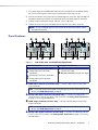
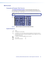
Panel Features
RS-232
HDMI
1 2
AUDIO AUDIO HDMI
FOX DR HD
Tx
Rx
RxTx RxTx
SIGNAL
HDCP
Rx GTx
RS-232
Rx GTx
SIGNAL
HDCP
OPTICAL OPTICAL
OUTPUTS
2
Tx
Rx
2
1
Tx
INPUTS
RS-232
HDMI AUDIO AUDIO HDMI
FOX DT HD
Rx
RxTx RxTx
SIGNAL
HDCP
Rx GTx
RS-232
Rx GTx
SIGNAL
HDCP
OPTICAL OPTICAL
INPUTS
2
Tx
Rx
AABB CCDD
EE EEFF
FF
Figure 4. FOX DT HD (Left) and FOX DR HD (Right) Panels
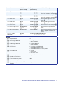
Inputs and Outputs Throughput and Control
A
HDMI input connector (see below)
B
Analog audio input connector
(see below)
C
HDMI output connector (see below)
D
Analog audio output connector
(see below)
E
Fiber connector and LED indicators
(see the next page)
F
RS-232 connector (see the next page)
A
HDMI input connector (transmitter only) — Connect video sources to the HDMI
input connectors.
TIP: Use Extron HDMI LockIt Cable Lacing Brackets to secure HDMI cables to the
device (see HDMI Connection on page 9).
B
Analog audio input connector (transmitter only) — Connect an analog audio
source to the 3.5 mm tip-ring-sleeve (TRS) connector (see Analog Audio Connection
on page 10 for wiring considerations).
C
HDMI output connector (receiver only) — Connect a display device to the HDMI
output connectors.
TIP: Use Extron HDMI LockIt Cable Lacing Brackets to secure HDMI cables to the
device (see HDMI Connection on page 9).
D
Analog audio output connector (receiver only) — Connect an audio output device
to this 3.5 mm TRS connector (see Analog Audio Connection on page 10 for wiring
considerations).

PowerCage 401 Dual Fiber Optic Boards • Installation 8
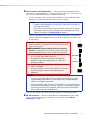
E
Fiber connector and LED indicators — Connect a fiber optic cable between fiber
connectors on compatible devices. The fiber connector is split into a Tx port and an Rx
port. To wire the fiber connector ports, consider the following:
• For one-way video, audio, and serial communication, connect a fiber optic cable
between the Tx port on one device and the Rx port on another.
NOTES:
• For point-to-point applications, connect the Tx port on the transmitter to
the Rx port on a receiver.
• To connect up to ten receivers to one transmitter, connect the Tx port on
each receiver to the Rx port on another receiver and enable Daisy Chain
mode on the receivers (see Daisy Chain on page 10).
• To return serial data from the receiver to the transmitter or for HDCP compliance,
connect a fiber optic cable between the Rx port on the transmitter and the Tx port
on the receiver.
WARNING: Potential risk of severe injury. The product
outputs continuous invisible light, which may be harmful to the
eyes; use with caution.
AVERTISSEMENT: Risque potentiel de blessure grave ou
de mort. Le produit émet une lumière invisible en continu qui
peut être dangereux pour les yeux, à utiliser avec précaution.
• Do not look into the rear panel fiber optic cable connectors
or into the fiber optic cables themselves.
• Ne regardez pas dans les connecteurs de câble fibre
optique sur le panneau arrière ou dans les câbles fibre
optique eux-mêmes.
• Plug dust caps into the optical transceivers when the fiber
cable is unplugged.
• Branchez protections contre la poussière dans l’ensemble
émetteur/récepteur lorsque le câble fibre optique est
débranché.
NOTES:
• Ensure the type of fiber optic cable is compatible with the device. Typically,
singlemode fiber optic cable has a yellow jacket and multimode fiber optic
cable has an orange or aqua jacket.
• Only one fiber optic cable, transmitter-Tx-to-receiver-Rx, is required for video,
audio, and serial command transmission. However, the HDMI signal output on
the receiver will not be HDCP-compliant and the transmitter will not receive
RS-232 reports from the controlled device.
The Link LED indicators light when there light is present on either fiber optic port.
F
RS-232 connector — Connect a control device or controlled device to this 3-pole
captive screw connector for pass-through RS-232 serial control (see RS-232
Connection on page 11).
Tr
ansmitter
to
Receiver
OPTICAL
Rx
Tx
OPTICAL
Rx
Tx

PowerCage 401 Dual Fiber Optic Boards • Installation 9
Connection Details
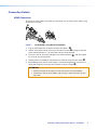
HDMI Connection
To secure the HDMI cable to the HDMI input connector, use an Extron LockIt Cable Lacing
Bracket and a tie wrap.
3
1
2
3
4
5
Figure 5. LockIt Cable Lacing Bracket Installation
1. Plug the HDMI cable into the panel connector (see figure 5,
1
).
2. Loosen the HDMI connector mounting screw from the panel (
2
) enough to allow the
LockIt to be placed over it. The screw does not have to be removed.
3. Place the LockIt on the screw and against the HDMI connector (
3
), and then tighten
the screw to secure the bracket.
4. Loosely place the included tie wrap around the HDMI connector and the LockIt (
4
).
5. While holding the connector securely against the cable lacing bracket, use pliers or a
similar tool to tighten the tie wrap, then remove any excess length (
5
).
ATTENTION:
• Connect and pulll the tie wraps until they are secure. Do not overtighten.
• Connectez et tirez les serre-câbles jusqu’à ce qu’ils soient sécurisés. Ne pas
trop serrer.

PowerCage 401 Dual Fiber Optic Boards • Installation 10
Analog Audio Connection
Wire the analog audio connector as shown in figure 6.
Tip (+)
Sleeve ( )
Sleeve ( )
Ring (
-
)
Tip (+)
Audio Plugs.eps
RCA Connector
3.5 mm Stereo Plug Connector
(balanced)
Sleeve ( )
Ring (R)
Tip (L)
3.5 mm Stereo Plug Connector
(unbalanced)
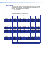
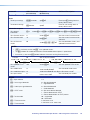
Figure 6. Analog Audio Connector Wiring
The following table shows the audio format sent over the fiber connection when a specific
audio format is not specified (see the Audio input selection SIS commands on page 27 to
switch the active audio source).
Auto Audio Input Format
HDMI Embedded Audio
Present
Analog Audio Present Audio Sent Over Fiber
Yes No HDMI embedded audio
Yes Yes HDMI embedded audio
No Yes Analog audio
No No No audio
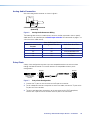
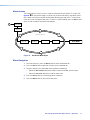
Daisy Chain
A daisy chain configuration connects up to ten compatible receivers to one transmitter
through the fiber connection. Ensure the receivers are compatible with daisy chain
configurations.
From Transmitter
or Daisy-Chained
Receiver
Receiver Receiver
Tx
Rx
Tx
Rx
Figure 7. Daisy Chain Configuration
1. Connect the Tx port on the transmitter to the Rx port on a receiver.
2. For all subsequent receivers except the last one in the order, connect the Tx port to the
Rx port on the next receiver.
3. To return serial data from the receivers to the transmitter or for HDCP compliance,
connect the Tx port on the last receiver to the Rx port on the transmitter.

PowerCage 401 Dual Fiber Optic Boards • Installation 11
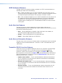
RS-232 Connection
Wire the remote RS-232 connector as shown in figure 8. The default baud rate is 9600.
NOTE: To set RS-232 protocol, use the serial port parameter SIS commands for the
enclosure (see the PowerCage 401 Enclosure User Guide at www.extron.com).
Figure 8. RS-232 Wiring
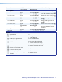
There are three methods of RS-232 insertion. Each transmitter and receiver requires a
method to be selected. By default, they are set to captive screw pass through. To set a
method, use the RS-232 insertion SIS commands (see transmitter RS-232 insertion
method commands on page 28 or receiver RS-232 insertion method commands on
page 33) or the Product Configuration Software (see Configuration Software on page 36).
• Captive screw pass through — Passes serial data over the fiber and RS-232
connection on a transmitter or receiver.
• Ethernet to captive screw — Passes serial data over the Ethernet connection on the
enclosure and an RS-232 connection on a transmitter or receiver.
• Ethernet to fiber — Passes serial data over the Ethernet connection on the enclosure
and a fiber connection on a transmitter or receiver.
Operation
After all related devices are connected and powered, the system is fully operational. If any
problems are encountered, verify that the cables are routed and connected properly. If
problems persist, call the Extron S3 Sales & Technical Support Hotline (see the contact
numbers on the last page of this guide for the nearest Extron office).

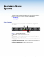
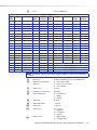
PowerCage 401 Dual Fiber Optic Boards • Operation 12
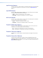
Enclosure Menu
System
This section describes the general PowerCage 401 menu system and specific features for
the FOX DT HD and FOX DR HD. Topics in this section include the following:
• Menu Overview
• Transmitter Menu
• Receiver Menu
Menu Overview
The PowerCage 401 menu system provides a local method of basic configuration and
status indication.
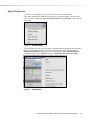
ADJUST
MENU
NEXT
RESET
POWERCAGE 401
POWER SUPPLY
POWER SUPPLY
CONFIG
Extron
B
CD
A
E
Figure 9. PowerCage 401 Front Panel
A
LCD screen — Displays the enclosure menu system.
B
Menu button — Cycles through the root menu or exits a slot menu. If changes are
made in the slot menu, changes are saved.
C
Next button — Selects a slot menu from the root menu or cycles through submenus in
a slot menu.
D
Horizontal (
[
) adjustment knob — Selects an individual transmitter or receiver in a
slot.
E
Vertical (
{
) adjustment knob — Selects a value for a submenu.
La page est en cours de chargement...
La page est en cours de chargement...
La page est en cours de chargement...
La page est en cours de chargement...
La page est en cours de chargement...
La page est en cours de chargement...
La page est en cours de chargement...
La page est en cours de chargement...
La page est en cours de chargement...
La page est en cours de chargement...
La page est en cours de chargement...
La page est en cours de chargement...
La page est en cours de chargement...
La page est en cours de chargement...
La page est en cours de chargement...
La page est en cours de chargement...
La page est en cours de chargement...
La page est en cours de chargement...
La page est en cours de chargement...
La page est en cours de chargement...
La page est en cours de chargement...
La page est en cours de chargement...
La page est en cours de chargement...
La page est en cours de chargement...
La page est en cours de chargement...
La page est en cours de chargement...
La page est en cours de chargement...
La page est en cours de chargement...
La page est en cours de chargement...
La page est en cours de chargement...
La page est en cours de chargement...
La page est en cours de chargement...
La page est en cours de chargement...
La page est en cours de chargement...
La page est en cours de chargement...
-
 1
1
-
 2
2
-
 3
3
-
 4
4
-
 5
5
-
 6
6
-
 7
7
-
 8
8
-
 9
9
-
 10
10
-
 11
11
-
 12
12
-
 13
13
-
 14
14
-
 15
15
-
 16
16
-
 17
17
-
 18
18
-
 19
19
-
 20
20
-
 21
21
-
 22
22
-
 23
23
-
 24
24
-
 25
25
-
 26
26
-
 27
27
-
 28
28
-
 29
29
-
 30
30
-
 31
31
-
 32
32
-
 33
33
-
 34
34
-
 35
35
-
 36
36
-
 37
37
-
 38
38
-
 39
39
-
 40
40
-
 41
41
-
 42
42
-
 43
43
-
 44
44
-
 45
45
-
 46
46
-
 47
47
-
 48
48
-
 49
49
-
 50
50
-
 51
51
-
 52
52
-
 53
53
-
 54
54
-
 55
55


Extron PowerCage 401 FOX DR HD Manuel utilisateur
- Catégorie
- Commutateurs vidéo
- Taper
- Manuel utilisateur
- Ce manuel convient également à
dans d''autres langues
Documents connexes
-
Extron FOX II T HD 4K Manuel utilisateur
-
-
-
-
Extron FOX II T DP 4K Manuel utilisateur
-
-
-
-
-