Legrand Concerto I8G Manuel utilisateur
- Catégorie
- Équipement musical supplémentaire
- Taper
- Manuel utilisateur
Ce manuel convient également à

Concerto
™
6 Sound Sources, 8 Listening Zones,
and Generation D Digital Amplification
∑NV-I8DMS Installation Manual

ENGLISH
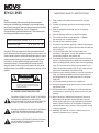
Danger
Exposure to extremely high noise levels may cause a permanent
hearing loss. Individuals vary considerably to noise induced hearing
loss but nearly everyone will lose some hearing if exposed to sufficiently
intense noise for a sufficient time. The U.S. Government's
Occupational Safety and Health Administration (OSHA) has specified
the following permissible noise level exposures:
1DURATION PER DAY (HOURS)86432
SOUND LEVEL (dB) 90 93 95 97 100 103
According to OSHA, any exposure in the above permissible limits could
result in some hearing loss. Ear plugs or protectors in the ear canal or over
the ears must be worn when operating this amplification system in order to
prevent a permanent hearing loss. If exposure in excess of the limits as
put forth above, to insure against potentially harmful exposure to high
sound pressure levels, it is recommended that all persons exposed to
equipment capable of inducing high sound pressure levels, such as this
amplification system, be protected by hearing protectors while this unit is in
operation.
CAUTION:
CAUTION
THIS SYMBOL IS INTENDED TO ALERT THE USER TO THE PRESENCE
OF NON-INSULATED "DANGEROUS VOLTAGE" WITHIN THE
PRODUCT'S ENCLOSURE THAT MAY BE OF SUFFICIENT MAGNITUDE
TO CONSTITUTE A RISK OF ELECTRIC SHOCK TO PERSONS.
THIS SYMBOL IS INTENDED TO ALERT THE USER TO THE PRESENCE
OF IMPORTANT OPERATING AND MAINTENANCE (SERVICING)
INSTRUCTIONS IN THE LITERATURE ACCOMPANYING THE UNIT.
RISK OF ELECTRIC SHOCK
DO NOT OPEN
TO REDUCE THE RISK OF ELECTRIC SHOCK, DO
NOT REMOVE CHASSIS. NO USER-SERVICEABLE
PARTS INSIDE. REFER SERVICING TO QUALIFIED
SERVICE PERSONNEL.
AVIS: RISQUE DE CHOC ELECTRIQUE-NE PAS OUVRIR.
APPARATUS SHALL NOT BE EXPOSED TO DRIPPING OR SPLASHING
AND THAT NO OBJECTS FILLED WITH LIQUIDS, SUCH AS VASES,
SHALL BE PLACED ON THE APPARATUS.
IMPORTANT SAFETY INSTRUCTIONS
1.� Read all safety and operating instructions before using this
product.
2.� All safety and operating instructions should be kept for future
reference.
3.� Read and understand all warnings listed on the operating
instructions.
4.�Follow all operating instructions to operate this product.
5.� This product should not be used near water, i.e. Bathtub,
sink,swimming pool, wet basement, etc.
6.� Only use dry cloth to clean this product.
7.� Do not block any ventilation openings, It should not be placed flat
against a wall or placed in a built-in enclosure that will impede the
flow of cooling air.
8.� Do not install this product near any heat sources ;such
as,radiators, heat registers, stove or other apparatus (including
heat producing amplifiers) that produce heat.
9.� Do not defeat the safety purpose of the polarized or grounding-
type plug. A polarized plug has two blades with one wider than the
0ther.A grounding-type plug has two blades and a third grounding
prong. The wide blade or the third prong are provided for your
safety If the provided plug does not fit into your outlet, consult an
electrician for replacement of the obsolete outlet.
10.� Protect the power cord being walked on or pinched, particularly at
Plugs, convenience receptacles and the point where they exit
from the apparatus. Do not break the ground pin of the power
supply cord.
11. Only use attachments specified by the manufacturer.
12.� Unplug this apparatus during lightning storms or when unused for
long periods of time.
13.� Care should be taken so that objects do not fall and liquids are
not spilled into the unit through the ventilation ports or any other
openings.
14.� Refer all servicing to qualified service personnel. Servicing is
required when the apparatus has been damaged in any way;
such as, power-supply cord or plug is damaged, liquid has been
spilled or objects have fallen into the apparatus, the apparatus
has been exposed to rain or moisture, does not operate normally
or has been dropped.
15.� WARNING: To reduce the risk of fire or electric shock, do not
expose this apparatus to rain or moisture.

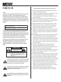
FRENCH
Danger
L‘exposition a des niveaux eleves de bruit peut provoquer une perte
permanente de l’audition, Chaque organisme humain reagit
differemment quant a la perte de l’audition, mais quasiment tout le
monde subit une diminution de I’acuite auditive lors d’une exposition
suffisamment longue au bruit intense. Les autorites competentes en
reglementation de bruit ont defini les expositions tolerees aux niveaux
de bruits:
8 6 4321DURE EN HEURES PAR JOUR
INIVEAU SONORE CONTINU EN dB 90 93 95 97 100 103
Selon les autorites, toute exposition dans les limites citees ci-dessus,
peuvent provoquer certaines pertes d’audition. Des bouchons ou
protections dans l’appareil auditif ou sur l’oreille doivent etre portes lors
de l’utilisation de ce systeme d’amplification afin de prevenir le risque
de perte permanente de l’audition, Dans le cas d’expositions
superieures aux limites precitees il est recommande, afin de se
premunir contre les expositions aux pressions acoustiquese I evees
potentielIement dangeure u ses, aux personnes exposees aux
equipements capables de delivrer de telles puissances, tels ce
systeme d’amplification en fonctionnement, de proteger l’appareil
auditif.
ATTENTION: AFIN DE LlMlTER LE RISQUE DE CHO ELECTR/QUE, NE
PAS ENLEVER LE CHASSIS. NE CONTIENT PAS DE
PIECES POUVANT ETRE REPAREE PAR L’UTILISATEUR.
CONFER LE SERVICE APRES-VENTE AUX
REPARATEURS
ATTENTION
RISQUE DE CHOC ELECTRIQUE
NE PAS OUVRIR.
CE SYMBOLE A POUR BUT D'AVERTIR L'UTILISATEUR DE LA PRESENCE
DE VOLTAGE DANGEREUX NON-ISOLE A L'INTERIEUR DE CE PRODUIT
QUI PEUT ETRE DE PUISSANCE SUFFISAMMENT IMPORTANTE POUR
PROVOQUER UN CHOC ELECTRIQUE AUX PERSONNES.
CE SYMBOLE A POUR BUT D'AVERTIR L'UTILISATEUR DE LA PRESENCE
D'INSTRUCTIONS D'UTILISATION ET DE MAINTENANCE DANS LES
DOCUMENTS FOURNIS AVEC CE PRODUIT.
AFIN DE REDUIRE LES RISQUÉ D'INCENDIE ET DE DECHARGE
ELECTRIQUE, NE PAS EXPOSER CET APPAREIL A LA PLUIE OU A
L'HUMIDITE.
IMPORTANTES INSTRUCTIONS DE SECURITE
1.� Lire avec attention toutes les recommandations et précautions
d'emploi avant d'utiliser ce produit.
2.� Toutes les recommandations et précautions d'emploi doivent être
conservées afin de pouvoir s'y reporter si nécessaire.
3.� Lire et comprendre tous les avertissements énumérés dans les
précautions d'emploi.
4.� Suivre toutes les précautions d'emploi pour utiliser ce produit.
5.� Ce produit ne doit pas être utilisé près d'eau, comme par exemple
baignoires, éviers, piscine, sous-sol humides ... Etc.
6.� Utiliser exclusivement un chiffon sec pour nettoyer ce produit.
7.� Ne bloquér aucune ouverture de ventilation. Ne pas placer le
produit tout contre un mur ou dans une enceinte fern
ée, cela
gênerait le flux d'air nécessaire au refroidissement.
8.� Ne pas placer le produit près de toute source de chaeur telle que
radiateurs, arrivées d'air chaud, fourneaux ou autres appareils
générant de la chaleur (incluant les amplificateurs producteurs
de chaleur) .
9.� Ne pas négliger la sécurité que procure un branchement polarisé
ou avec raccordement à la terre, Un branchement polarisé
comprend deux fiches dont l'une est plus large que l'autre. Un
branchement à la terre comprend deux fiches plus une troisième
reliée à la terre. Si la fiche secteur fournie ne s'insert pas dans
votre prise de courant. consulter un 'électricien afin de remplacer
votre prise obsolète.
10.
Protéger
le cordon d'alimentation de tout écrasement ou
pincement, particulièrement au niveau des fiches, des
réceptacles utilisés et à l'endroit de sortie de l'appareil. Ne pas
casser la fiche de terre du cordon d'alimentation.
11.Utiliser uniquement les accessoires spécifiés par le constructeur.
12. Débrancher cet appareil lors d'orages ou s'il n'est pas utilisé
pendant une longue période.
13. Des précautions doivent être prises afin qu'aucun objet ne tombe
et qu'aucun liquide ne se répande à l'intérieur de l'appareil par
les orifics de ventilation ou n'importe quelle autre ouverture.
14. Pour toutes interventions techniques s'adresser à un technicien
qualifié.L'intervention technique est nécessaire lorsque l'appareil
a été endommagé de n'importe quelle façon, comme par
exemple si le cordon secteur ou sa fiche sont détériorés,si du
liquide a coulé ou si des objets sont tombés à l'intérieur de
l'apparei1,si l'appareil a été exposé à la pluie ou à l'humidité, s'il
ne fonctionne pas normalement ou s'il est tombé.
15. ATTENTI0N:Pour réduire le risque d'incendie ou de choc
electrique ne pas exposer l'appareil à la pluie ou à l'humidité.

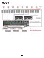
Concerto
6 Sound Sources, 8 Listening Zones, and
Generation D Digital Amplification
Introduction
Congratulations on the purchase of your NuVo System. The Concerto System represents the finest in audio dis-
tribution technology. From the inside out, Concerto performs at a superior level, while at an incomparable price
to anything in the home audio industry.
Concerto delivers 80 startlingly clear watts of sound to up to 16 independent zones simultaneously. NuVo’s
Generation D, class D, amplification uses the newest technology in digital amplification, which requires less
power and is able to operate at peak capacity while generating very little heat.
The Concerto Display Pad is sleek, elegant, and designed to complement any home décor. The vacuum fluores-
cent display is capable of providing feedback for multiple user commands and is easily read in any room environ-
ment. Its numeric keypad is ideal for access to multiple disc changers and tuners from any room of the house.
Easy access HotKey functions allow each Display Pad to be set in a "Do Not Disturb" mode, Source Monitoring
from any zone, and setting any of the Display Pads to perform as a master control for the entire house.
The EZ IR Learning Station makes system setup easy and intuitive. Creating customized displays is as easy as
typing in a Windows template. The Learning Station will allow IR commands for the source equipment to be
stored in files for future use, making programming the system as simple as the push of a button.
This installation manual outlines the installation and setup of your new Concerto System. We recommend that
you read this manual prior to installing your system. Proper installation and setup will insure years of audio
enjoyment.
Concerto System Package Contents:
• NV-I8DMS amplifier
∑
• 6 NV-I8DSP Display Pads with white, ivory, and almond, inserts and trim plates
∑
• 6 NV-VEC IR emitters
∑
• 1 NV-I8EZP EZ Port connection hub
∑
• 1 Network cable
Tools needed for Installation:
Small flat head screwdriver
Small phillips screwdriver
Wire stripper
RJ-45 crimp tool
Cat-5 wire tester
NV-I8DLS IR Learning Station with Configurator Software
4

5

Quick Start Guide
Your Concerto Audio Distribution System is quick and easy to install. This guide outlines the necessary steps for an accu-
rate and successful installation—and years of audio enjoyment for your customers.
Step 1: Check your package for all of the components. Your box should contain the following items:
• 1 NV-I8M six-source, eight-zone amplifier
• 6 NV-I8DDSP Display Pad zone controllers, each containing white, ivory, and almond inserts
and screwless trim plates.
• 1 NV-NC1 10’ network cable
• 1 NV-I8EZP EZ Port Multi-port connection hub
• 6 NV-VEC IR emitters with feedback LED
• 1 Installation manual
Step 2: Place the Concerto amplifier in its preferred location. The Concerto amplifier is designed to be located in the cen-
tral media area where the home’s audio sources will be housed.
Step 3: The Concerto amplifier should be turned on before any other cables are attached to it. This activates internal pro-
tective circuitry. Once the Concerto amplifier is turned on, it should be left on.
Step 4: When the amplifier has been placed in its location, the audio sources can be connected using standard stereo RCA
cables (see page 13).
Step 5: The IR (infrared) emitters should be plugged into the IR outputs and attached to the IR receiver window of the
appropriate source equipment (see page 13).
Step 6: Each of the Cat-5 cables from the zones should be crimped with an RJ-45 connector using the 568A or 568B net-
work wiring scheme (see page 10 for Cat-5 crimping instructions). Test each Cat-5 connection using a cable tester before
proceeding with the installation. These cables each plug into their own RJ-45 connection jack on the back of the supplied
EZ Port. It is important for future reference to label each Cat-5 cable for its appropriate listening zone. The order in which
they are plugged into the EZ Port is irrelevant to the system’s operation.
Step 7: Connect the provided pre-terminated Network Cable in the RJ-45 connection jack on the front of the EZ Port and in
the Network Connection on the back of the Concerto amplifier.
Step 8: It is important for the following steps that you have the Concerto Configurator Software, available with the pur-
chase of the IR Learning Station, installed on your computer. Within the Configurator you will establish the IR libraries
for the sources and specific source functions, name the sources, establish the specific zones, and set the operational prop
-
erties for each zone (this is covered in detail in section X: Using the Concerto Configurator Software, page 14).
Step 9: The Configuration for the system can be done off-site and then loaded into the Concerto using the RS232 interface.
Once loaded, the remainder of the installation can be completed.
Step 10: When the Display Pads are added to each zone, the system will poll for available zones and allow you to choose the
appropriate zone number for that Display Pad. (See page 22: Factory-new Installation.)
Step 11: Set the Display Pad for its appropriate zone. Once this is done, you will have complete control of that zone.
Step 12: Several menu options are available for tailoring the sound in each zone. By going into the keypad setup via the
menu key, you can adjust the treble and bass response, left and right channel balance, gain control, and source grouping.
(See page 22: Using the Display Pad’s MENU Button.)
Step 14: The fully functioning, programmed Concerto will control source selection and individual source functions. The
Display Pad is capable of displaying customized source names and programmed presets.
6

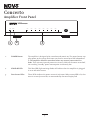
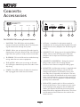
Concerto
Amplifier Front Panel
1. POWER Button: The amplifier is designed to be turned on and remain on. The power button sup-
plies power to the system. Each zone can then be turned on or off independent-
ly. The amplifier should be turned on before any external connections are
made. This activates internal protective circuitry. With all the zones turned off,
the resulting "standby" power consumption is extremely low.
2. STAND-BY LED: This blue LED (light-emitting diode) will indicate that the amplifier is plugged
in to an AC outlet source.
3. Zone Status LEDs: These LEDs indicate the power status of each zone. When a zone LED is lit, that
zone is currently turned on, as commanded by the zone Display Pad.
7
Concerto
Whole-Home Audio System
ZONE 1
ZONE 2
ZONE 3
ZONE 4
ZONE 5
ZONE 6 ZONE 7
ZONE 8
POWER
STAND BY
1
2
3

8
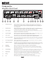
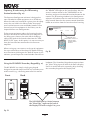
Concerto
Amplifier Back Panel
1. Variable Lineouts: These preamp lineouts are used for sending an audio signal to an external power
amplifier. This is useful for large areas that require additional pairs of speakers. Use
the variable output when you want the additional amplifier to be controlled by the
zone’s Display Pad.
2. Fixed Lineouts: These preamp lineouts are used for sending an audio signal to an external power
amplifier when additional speakers are needed. This output is constant, so an amplifi-
er connected to it will not change volume with that zone’s Display Pad.
3. Source Inputs: The Concerto will accept up to six audio sources. These are connected to the Concerto
amplifier with standard stereo RCA cables.
4. Speaker Output: Six of the Concerto’s eight zones are amplified. These outputs accept 16-gage, two-con-
ductor speaker wire and provide 40 watts per channel of power.
5. Source Link: This connection is used in conjunction with the Concerto Expander System to create
16 total zones. The source link cable is supplied with the Expander System.
6. Source Status Inputs: These optional inputs can be used to monitor source power status. This is useful when
using a macro string of commands to prevent turning off a piece of equipment that is
already on and vice versa.
7. Zone Trigger Outputs: These 12-volt outputs can be used to trigger an external device, such as an auxiliary
power amplifier, for use in a specific zone.
8. IR Emitter Outputs: IR signals received from the keypads are passed through the IR outputs to the source
equipment using the supplied IR emitters. Outputs 1-6 are routed to the corresponding
sources, and the SUM outputs 1 and 2 are common and will pass all IR signals.
9. SYS. ON: This is a constant 12-volt output for turning on external equipment.
10. EXT. MUTE: This input is designed to temporarily mute any audio playing through the system
when the doorbell or phone rings. This works in conjunction with the NuVo NV-MI1
mute interface accessory.
11. Network Input: This RJ-45 connection is the input for all zone information coming from the Concerto
Display Pads. The connection is made using the Network Cable supplied with the package.
12. Digital Link: This connection is used in conjunction with the Concerto Expander System to create
16 total zones. The Digital Link cable is supplied with the Expander System.
13. RS232: The bidirectional RS232 is a serial communication port that allows the Concerto
System to be controlled by an external home automation device.
14. AC: A detachable power cord connects the system to an external AC power supply.
R
OUTPUT POWER
OUTPUT POWER
20W/6OHM X2
20W/6OHM X2
SYS ON
EXT. MUTE
L
R
L
R
L
R
VARIABLE
OUTPUT
FIXED
OUTPUT
SUM1
3033118
C
US
CONFORMS TO
UL STD.6500
CERTIFIED TO
CAN/CSA STD.E60065
NuVo Technologies CincinnatiOhio USA
FUSE:T5 A
120V 60Hz 500W
MODEL NV-I8DM
SIX SOURCEEIGHT ZONE
AUDIO DISTRIBUTIONSYSTEM
www.nuvotechnologies.com
OUTPUT POWER
OUTPUT POWER
OUTPUT POWER
20W/6OHM X2
20W/6OHM X2
20W/6OHM X2
TIP=L
RING=R
VARIABLE
OUTPUT
FIXED
OUTPUT
TIP=L
RING=R
VARIABLE
OUTPUT
FIXED
OUTPUT
TIP=L
RING=R
VARIABLE
OUTPUT
FIXED
OUTPUT
TIP=L
RING=R
VARIABLE
OUTPUT
FIXED
OUTPUT
TIP=L
RING=R
VARIABLE
OUTPUT
VARIABLE
OUTPUT
FIXED
OUTPUT
FIXED
OUTPUT
TIP=L
RING=R
TIP=L
RING=R
12 34 5
6
12 34 5
6
23
4
1
1
23
RS-232
CONNECT TO
NV-I8X
USE NV-SLC1
CABLE
CONNECT TO
NV-I8X
USE NV-SLC1
CABLE
CONNECT TO
NV-I8EZP1
USE NV-NC1
CABLE
USE CNLY WITH 250V FUSE
4
5
6
SUM2
567
8
OUTPUT POWER
20W/6OHM X2
ZONE 6ZONE 6
ZONE 7&8
SYSTEM
ZONE TRIGGER OUTPUTS
SOURCE LINK
SOURCE INPUTS
ZONE 1
NETWORK
EMITTER OUTPUTS
DIGITAL LINK
ZONE 3
ZONE 4
ZONE 5
ZONE 2
PROGRAM
6
4
5
3
1
2
SOURCE STATUS INPUTS
1
2
3
4
5
6
7
8
9
10
11
12
14
13

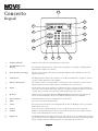
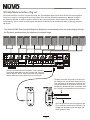
Concerto
Keypad
LOCK
DIM
MASTER
DND
POWER
VOLUME
1
4
7
+10
CONT
2
5
8
0
SHUF
3
6
9
ENT
MENU
MUTE DISCGRP
SOURCE
1
2
3
4
5
6
7
8
9
10
11
12
13
HOTKEY
PLAY
SYSTEM ON
DO NOT DISTURB
1. Volume Indicator: Volume level of the zone is displayed as a bar graph.
2. Vacuum Fluorescent
Display: The display is designed to be easily read in any light. It is capable of displaying 16
alphanumeric figures in a string.
3. Zone Parameter Settings: Specific zone settings such as Do Not Disturb, Master, Mute and Monitor are dis-
played in red text.
4. IR Indicator: The Display Pad indicates the initiation of an IR command with a sequence of three
red arcs on the right side of the display.
5. Numeric Entry Keys: The numeric keys are configurable for each audio source and can be used to access
specific CD, tuner and satellite stations, and music server selections.
6. Menu: The menu key serves two functions. It allows the user to access specific settings in
each zone, such as bass and treble, balance, and panel brightness, and it serves as a
"hotkey" that provides a second level of functionality for each source.
7. Hotkeys: When used in conjunction with the MENU/HOTKEY, these buttons provide quick
access to Do Not Disturb, whole-house Master, Display Pad Lock, and Dim.
8. Function Keys: Individual functions can be configured for each source.
9. Mute: The zone can be muted temporarily.
10. Power: The power button turns the zone Display Pad on and off. Holding it in for 3 seconds
turns all the zones off.
11. Source: The source key scrolls through the sources connected to the Concerto System.
12. Volume: Volume is independently increased or decreased in each zone. The Volume key also
serves as the IR (infrared) receiver window.
13. RJ45 Ports: The Display Pad has two RJ45 connections. The first is used to communicate via Cat-
5 wire with the Concerto amplifier component, and the second is a parallel input that
allows a single-gang secondary keypad to be daisy-chained in each zone.
9

1 2 3 4 5 6 7 8
Top view with
tab down.
Wires insert from
this end.
Pair 2
Pair 3
Pair 4
Pair 1
t
IR
Bus C n rl
o
o
I
r
ouR G nd
r
i
a a
t B
us
S
e
l
D a
-
l
Ser
i
a
Da
ta B
u
s+
I
ig
a
lRS
n
u
n
P
o
we
r
G
ro
d
2
4
V
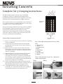
Complete Cat 5 Crimping instructions
The NuVo audio systems require Cat 5, unshielded,
twisted pair (UTP), for communication between the
keypads/Display Pads and the main amplifier unit. Each
end of the wire is terminated with an RJ45 connector.
The concerto System can accommodate 2000 total feet of
Cat 5 cable. For the most reliable operation, it is best that
no single run of Cat 5 exceeds 250 feet.
The correct wiring scheme for the Cat 5 cable is standard
EIA/TIA 568A. Properly terminating the Cat 5 cable is
crucial for the operation of the system. It is very
important to use a good quality crimp tool, and testing
each end to end run with a Cat 5 wire tester will insure
that your system operates flawlessly.
Step-by-Step Crimping Instructions
! 1. Strip a 2 to 3 inch portion of the insulation, exposing
the 4 twisted pairs.
!2. Untwist the wires and fan them out individually.
Arrange the wires into the correct color scheme as
shown in Fig. 1.
!3. Flatten the wires in their correct order, and trim
them evenly across the top. Most crimp tools have a
wire trimmer built-in. It is best to trim the wires to
about ½” in length.
!4. While holding the wires flat between your thumb
and forefinger, insert the wires into the RJ45
connector, so each is in its own slot. Push the wire
into the RJ45, so all 8 conductors touch the end of
the connector. The insulation jacket should extend
beyond the crimp point of the RJ45.
!5. Insert the RJ45 into the crimp tool receptacle and
squeeze the tool firmly. Note that a ratchet type tool
should tighten down until it no longer clicks.
!6. The RJ45 should be firmly crimped to the Cat 5
insulation. It is necessary that the color scheme be
repeated identically on each end of the wire.
Fig. 1: EIA 568A wiring scheme for Cat 5 Cable
Pin #
1. Green Stripe
2. Green
3. Orange Stripe
4. Blue
5. Blue Stripe
6. Orange
7. Brown Stripe
8. Brown
Note: Colors listed as “stripe” are a white wire
with a colored stripe.
Step 1 Step 2 Step 3
Step 4 Step 5 Step 6
Installing Concerto
10

II. Terminating the Speaker Wire
(fig. 2)
All the NuVo systems operate across a "homerun"
wiring scheme using Cat-5 for the zone keypad control
communication, and a separate run of speaker wire for
each zone from the speaker outputs to the zone speak
-
ers. We suggest 16-gage 2- or 4-conductor speaker
wires.
The speaker wire termination is done using a modular
"Euro" connector. Each conductor is screwed down to
the connector block and plugged into the appropriate
speaker output on the back of the amplifier. The prop
-
er termination is Left channel – and +, Right channel –
and +.
LEFT
LEFT
RIGHT
RIGHT
III. Installing the Concerto Amplifier
-
+
-
+
System setup works best when the amplifier is placed
Fig. 2
in the same location as the audio source equipment.
This is typically in an audio rack, entertainment cen
-
ter, or a closet dedicated to housing the home
audio/video equipment.
The amplifier should be plugged in and the power but-
ton on the front panel should be depressed before pro-
ceeding with the rest of the installation. This activates
the internal protective circuitry of the Concerto
System.
11

12
IV. Installing the NV-I8EZP EZ Port
(fig.3)
The EZ Port is a multi-connection hub designed to
accept all the Cat-5 wires from the keypads in the sys-
tem. The location of the EZ Port should be determined
by the location of the Concerto amplifier. It is best to
place in a wall behind the amplifier that would be easi-
ly accessible if necessary.
The EZ Port fits easily in any dual-gang-size, low-volt-
age ring with an open back. These are often referred to
as "mud rings." Simply plug the terminated Cat-5 wires
into any of the 20 available jacks on the back of the EZ
Port. The order in which the individual Cat-5 wires are
plugged in is not important, although it is strongly rec-
ommended that you label the Cat-5 with the appropri-
ate zone number for future reference.
Once you have plugged the Cat-5 wires into the EZ
Port, screw the EZ port into its construction bracket
using the supplied mounting screws.
Fig. 3
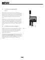
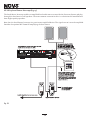
V. Connecting the EZ Port to the
Concerto Amplifier (fig. 4)
When the EZ Port is installed in the wall, the only part
visible should be the faceplate and four RJ45 jacks. The
supplied pre-terminated network cable should then be
plugged into the RJ-45 connection labeled “Connect to
the NV-I8M ONLY”. Any Cat-5 cable terminated using
568A or 568B network wiring will suffice should you
need a longer connection.
Fig. 4
SYSTEM
DIGITAL LINK
PROGRAM
CONNECT TO
NV-I8DX
USE NV-SLC1
CABLE
CONNECT TO
NV-I8DEZP
USE NV-NC1
CABLE
SYS ON
EXT. MUTE
NETWORK
EZ Port (front)
Concerto Network
Connection
Network Cable
Concerto EZ Port
NV-I8DEZP
Peripheral
Device 1
Peripheral
Device 2
Peripheral
Device 3
Connect to
NV-I8DM
ONLY

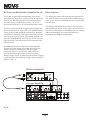
VI. Attaching Audio Source Equipment to the
Concerto Amplifier (fig. 5)
Each piece of audio equipment is connected to the
Concerto amplifier with standard stereo RCA cables.
Attach the RCA cable to the corresponding audio out-
put on the source equipment and to the desired source
input on the back of the Concerto amplifier. The num-
bered input for each source is important in the config-
uration of the system, and will be covered in detail in
the Concerto Configurator portion of this manual.
Fig. 5
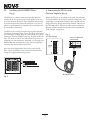
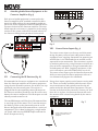
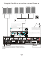
VII. Connecting the IR Emitters (fig. 6)
IR commands for the source equipment are transferred
from the Concerto amplifier to the source equipment
using the mini IR mouse emitters. Six of these are sup-
plied with your Concerto System. The emitter is
plugged into the corresponding source IR output on
the Concerto and then placed over the IR receiver win-
dow on the source component. The IR outputs are indi-
vidually routed to sources 1-6.
The two SUM outputs will flash any IR command that
is sent from any of the zones. This is used to connect
the NuVo T3 Tuner to the Concerto System or an IR
blaster designed to flash IR commands to a variety of
components. This is done by plugging a single mono
1/8" patch cable into the SUM IR output and into the
Direct IR input on the T3.
Fig. 6
VIII. Source Status Inputs (fig. 7)
The source status inputs can be very useful for moni-
toring the power status of your audio sources. Some
equipment uses "toggling commands" for powering on
and off (that is, the commands for on and off are not
separate discrete commands). This situation is typical-
ly confusing when using a single button to initiate to a
piece of source equipment a string of commands that
includes power on. With "toggling" equipment, if the
unit is already on, you will inadvertently turn it off.
The source status inputs give the Concerto System the
ability to sense that the source equipment is on so it
can automatically bypass that command.
Using these inputs requires an AC power-sensing mod-
ule. These are readily available from electronic acces-
sory manufacturers and typically attach to the AC
power cord of the desired source equipment. The con-
nection at the back of the concerto is a mono 1/8" jack.
Once this is in place, the Concerto System will sense
the amount of AC current being drawn by the source
equipment.
Fig. 7
Current sensor attaches to the
AC power cord of the source
equipment.
13
SYSTEM
ZONE TRIGGER OUTPUTS
EMITTER OUTPUTS
SYS ON
EXT. MUTE
SUM1
1 3
5
7
8
1
3 5
2
4
6
SUM2
2 4
6
6
dISC
COMPACT
SOURCE LINK
SOURCE INPUTS
ZONE 1
ZONE 3
ZONE 2
CONNECT TO
NV-I8X
USE NV-SLC1
CABLE
1 2 3 4 5
6
1 2 3 4 5
6
ZONE 1
ZONE 3
ZONE 2
OUTPUT POWER
OUTPUT POWER
OUTPUT POWER
20W/6OHM X2
20W/6OHM X2
20W/6OHM X2
VARIABLE
OUTPUT
VARIABLE
OUTPUT
VARIABLE
OUTPUT
FIXED
OUTPUT
FIXED
OUTPUT
FIXED
OUTPUT
TIP=L
RING=R
TIP=L
RING=R
TIP=L
RING=R
Source 1
Tuner 1
Audio
Out
2 3
4
5 6 7
8
ZONE TRIGGER OUTPUTS
ZONE 4
ZONE 5
6
4
5
3
1
1
2
SOURCE STATUS INPUTS

14
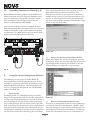
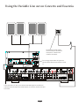
IX. Expanding Concerto to 16 Zones (fig. 8)
Eight additional listening zones can be added to the
Concerto System using the Concerto Expander pack-
age. The expansion is easily done using the Source
Link and Digital Link multi-pin outputs on the
Concerto main amplifier (NV-I8DMS).
The necessary cables for this are supplied with the
Expander package. No other connections are necessary
except the AC power cord and the additional speaker
terminations. The additional Cat-5 wires for the zones
9-16 plug into the Concerto main EZ Port.
Fig. 8
X. Using the Concerto Configurator Software
The following section requires the NV-I8DLS IR
Learning Station and Configurator Software. This is
available as a package from NuVo Technologies or any
Authorized NuVo Distributor. The Configurator soft-
ware is a PC program designed to run with Windows
2000, XP, and XP Pro.
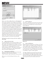
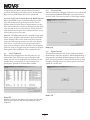
1. Main Startup
The Configurator is a tabbed Wizard-style interface
designed to sequentially walk the installer through the
system setup. When the program is launched, the Start
tab is highlighted. This gives three choices for begin-
ning a configuration. You can either create a new file,
open an existing file, or retrieve an existing file from a
configured Concerto System. Once configured, the fin-
ished program loaded into the Concerto main amplifier
can always be retrieved via the RS232 port and edited.
Once a configuration file has been opened, you can
then click on the next button to continue. The
Configurator will not let you continue beyond Start
without either creating a new file or opening an exist-
ing file. It will also prevent moving forward through
any of the tabs until the necessary information is com-
pleted in any one of the tabs.
Screen 1.0
1.1 Open or Create Concerto Configurator File
When you click on this button, the program goes to a
Config. File. There you can either open one of the exist-
ing configurations or specify the name of a new file.
Configurations are saved with a .cfg extension.
Screen 1.1
1.2 Retrieve Configuration from Concerto
To retrieve a configuration from an existing Concerto
installation, launch the Configurator software. Make
sure your computer is connected to the RS232 port on
the back panel of the Concerto amplifier. The Startup
screen has two buttons. The first is used to open an
R
OUTPUT POWER
OUTPUT POWER
20W/6OHM X2
40W/6OHM X2
SYS ON
EXT.MUTE
L
R
L
R
L
R
VARIABLE
OUTPUT
FIXED
OUTPUT
SUM1
3033118
C
US
CONFORMSTO
ULSTD.6500
CERTIFIEDTO
CAN/CSASTD.E60065
NuVoTechnologiesCincinnati Ohio USA
FUSE:T5A
120V 60Hz 500W
MODEL NV-I8DM
SIXSOURCE EIGHT ZONE
AUDIODISTRIBUTION SYSTEM
www.nuvotechnologies.com
OUTPUT POWER
OUTPUT POWER
OUTPUT POWER
40W/6OHM X2
40W/6OHM X2
40W/6OHM X2
TIP=L
RING=R
VARIABLE
OUTPUT
FIXED
OUTPUT
TIP=L
RING=R
VARIABLE
OUTPUT
FIXED
OUTPUT
TIP=L
RING=R
VARIABLE
OUTPUT
FIXED
OUTPUT
TIP=L
RING=R
VARIABLE
OUTPUT
FIXED
OUTPUT
TIP=L
RING=R
VARIABLE
OUTPUT
VARIABLE
OUTPUT
FIXED
OUTPUT
FIXED
OUTPUT
TIP=L
RING=R
TIP=L
RING=R
12 34 5
6
12 34 5
6
23
4
123
RS-232
CONNECT TO
NV-I8X
USE NV-SLC1
CABLE
CONNECT TO
NV-I8X
USE NV-SLC1
CABLE
CONNECT TO
NV-I8EZP1
USE NV-NC1
CABLE
USE CNLYWITH 250V FUSE
4
5
6
SUM2
567
8
OUTPUT POWER
40W/6OHM X2
ZONE 6ZONE 6
ZONE 7&8
SYSTEM
ZONE TRIGGEROUTPUTS
SOURCE LINK
SOURCE INPUTS
ZONE 1
NETWORK
EMITTER OUTPUTS
DIGITALLINK
ZONE 3
ZONE 4
ZONE 5
ZONE 2
PROGRAM
6
4
5
3
1
2
SOURCE STATUS INPUTS
R
ZONE 14
ZONE TRIGGEROUTPUTS
SOURCE LINK
ZONE 9
DIGITALLINK
ZONE 11
ZONE 12
ZONE 13
ZONE 10
CONNECT TO
NV-I8X
USE NV-SLC1
CABLE
11
9
13
15
12
10
14
16
CONNECT TO
NV-I8X
USE NV-SLC1
CABLE
OUTPUT POWER
OUTPUT POWER
OUTPUT POWER
OUTPUT POWER
OUTPUT POWER
OUTPUT POWER
40W/6OHM X2
40W/6OHM X2
40W/6OHM X2
40W/6OHM X2
40W/6OHM X2
40W/6OHM X2
VARIABLE
OUTPUT
VARIABLE
OUTPUT
VARIABLE
OUTPUT
VARIABLE
OUTPUT
VARI ABLE
OUTPUT
VARI ABLE
OUTPUT
FIXED
OUTPUT
FIXED
OUTPUT
FIXED
OUTPUT
FIXED
OUTPUT
FIXED
OUTPUT
FIXED
OUTPUT
TIP=L
RING=R
TIP=L
RING=R
TIP=L
RING=R
TIP=L
RING=R
TIP=L
RING=R
TIP=L
RING=R
VARIABLE
OUTPUT
FIXED
OUTPUT
TIP=L
RING=R
ZONE 15&16

e
xisting configuration or to create a new one. The sec-
ond asks to "Retrieve Existing Configuration From
Concerto." When you click on the "Retrieve" button, a
progress window will appear.
If you have this configuration already stored on your
computer’s hard drive, you will see a dialog box asking
if you wish to overwrite the existing file. If this file is
not stored in your computer, this box will not appear.
Screen 1.2
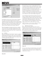
2.1 IR Libraries
The IR Library is a list of available components and
their IR function codes. The Configurator software
stores captured IR codes in a single directory. Once
captured or downloaded, the Configurator software
will permanently store it as a .irc file.
Screen 2.1
2.2 Adding a New Component to the IR Library
New component IR files are easily added by clicking on
the Add New button. This brings up a new window
titled Add New Component. In this window you must
first enter the manufacturer name and model. The Type
drop-down menu contains a large list of components. Each is
a template of common functions for that type of equip
-
ment. Clicking on the type that matches the compo-
nent will add the type name in that field. If desired,
you can add a type name that is not in the drop-down
menu. Some equipment operates at IR frequencies out-
side of the normal 38khz range. This can result in spo-
radic IR operation. To accommodate for variations in
IR modulation frequencies, the IR Library has an addi
-
tional drop-down menu titled "Carrier" for each source.
This allows you to manually choose 30, 36, 38, 40, or
56 as IR modulation frequencies. Most equipment
operates at the default 38khz, but as a general rule, the
following equipment operates best at a frequency out
-
side of 38khz. They are as follows: Mitsubishi and
Dennon is 30khz; Philips/Marantz is 36khz; Sony is
40khz; RCA/Thompson is 56khz.
Screen 2.2
Clicking on OK will automatically add that component
and associated functions to the IR Library.
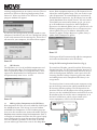
Using the IR Learning Station Interface (fig. 9)
To record new IR codes, you will need the IR Learning
Station Interface. The IR Learning Station Interface is
a powerful tool for setting up new IR Libraries for use
with the Configurator Software, and is part of the IR
Learning Station Package. Capturing function codes
and adding them to the component IR Library is an
easy process.
The Interface box is connected to your computer using
one of the RS232 connection cables provided with the
IR Learning Station package. The back panel of the
Interface box has two IR outputs for testing purposes.
You can use the included IR emitter and attach it to the
IR window on the face of the source component, or to
the built-in IR blaster, which, when aimed at the
source equipment, will fire the IR command.
READY POWER
Concerto Learning Station
Model NV-I8DLS
PASSTHRU
IR SENSOR
TEST ACTIVE
Hold thesource
remote control 8-10
inches from the
Learning Station
Interface.
15
Fig. 9

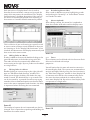
Screen 2.3
2.4
Screen 2.4
2.5
2.3 Recording IR codes
When a new component is added to the IR Library, it is
necessary to record the IR codes associated with each
function. To do this, connect the Learning Station
Interface as described above. Double-click on the
desired component from the IR Library page. This will
open the IR Library Editor. This window lists the com-
plete set of functions for that type of device.
To initiate the IR recording process, you can either
double-click on a function to be recorded or click on
the Record button. This will open the IR Library Record
window. The window will indicate that the
Configurator is "Waiting for IR Communications." To
record a new code, simply point the component’s
remote control at the IR receiver on the NuVo IR
Learning Station Interface. The first time you enter a
code, the Configurator determines if it is a "toggling
function," which means that the remote actually sends
two commands back-to-back. This requires that the
function button be pressed four times in succession.
When the remote code is entered, the IR Library
Record window will go from yellow to green and indi-
cate that the capture was successful, and it will then
return to yellow. Repeat this procedure three more
times until the desired code is added to the IR Library
Edit window. You will now see the number of code
repeats and the duration of the code. A normal non-tog-
gling remote will require two button pushes to success-
fully record a command, while a toggling remote will
require four button pushes for each command.
If there is an error in recording the code, the display in
the Record window will indicate that there was a com-
munication error. If this occurs, click on the Record
button and reenter the code.
IR Library Default Key Assignment
Once the desired codes are added, assign them to the
appropriate key on the Display Pad. To do this, right-
click on each code and select "Keys." This opens a drop-
down menu of the possible key selections for the
Concerto Display Pad. Select the appropriate key for
that command and the Configurator will add it to the
Default Key field for that command.
Once this sequence is completed, proceed to the next
function command, and repeat the above steps. When
you have assigned a default key for each IR, click on
"Done" and that component’s IR Library is complete.
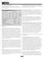
IR Library Test
A unique feature of the Concerto Configurator is the
ability to test each IR code as it is added to the IR
Library. This insures that every code will work reliably.
16

Screen 2.5
When a new code is added, while it is still highlighted,
click on the test button. This will open the IR Library
Test window. Make sure that the IR Learning Interface
box’s IR emitter is either facing the IR receiver window
of the source equipment or an IR emitter is plugged
into the IR emitter output and affixed to the IR receiv
-
er window of the source equipment. Clicking on the
test button will cause the IR Learning interface to emit
the code. The source equipment should respond appro
-
priately to the command if it has been stored correctly.
A test result box will open where you can record yes or
no to the test. Three successful test results are
required before the "Passed" count turns green.
Clicking the "OK" button will save the results in the IR
Library. The "Tested" column for that command will
show the number of successful tests performed.
Although not required, testing each code is highly rec-
ommended.
2.6 Adding a Function Code
If a required IR code is not in the list of codes, it is pos-
sible to add a code to the list by clicking the "Create
New" button. The pull-down menu contains a list of all
standard IR codes. A name not found in the list can be
typed in, but it is recommended that you use the
names provided in the list. This conserves memory in
the Concerto. Clicking on the "OK" button proceeds
directly to the IR recording process.
2.7 Cleaning Up an IR Library
Unused IR codes can be deleted from the list by high-
lighting the code and either clicking the
"Delete" button or right-clicking and selecting "Delete."
When you are finished editing the library, select
"Done."
Screen 2.7
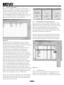
3. 0 Defining Sources
The "Sources" tab allows you to define the source com-
ponent attached to each of the six source inputs. All
six sources are not needed, but at least one source
must be defined.
Screen 3.0
3.1 Select or Edit Source
Double-clicking on a blank source will open the "Select
Source" window. This window assigns the appropriate
source number input. The "Display Name" is the text
that will be read on the Display Pad when that source
is selected in any zone. The display name can contain
only capital letters, numbers, and some punctuation. If
an invalid key is typed, it will be ignored.
The "Make" field defines the manufacturer of the equip-
ment. A drop-down menu allows you to choose a source
from the IR Library. The "Model" field provides a drop-
down menu that allows you to choose the specific piece of
source equipment from the selected manufacturer.
17

Screen 3.1
4. 0
Screen 4.0
Screen 4.1
An important feature of the "Select Source" window is
the "Gain" level control. Different pieces of source
equipment tend to have different levels of audio output
signal. This slider control allows you to compensate for
equipment that has an inherently lower volume level.
By using this adjustment, when switching between
sources, relative volume levels remain constant.
When the appropriate information has been complet-
ed, click "OK." This will add the updated source infor-
mation to the "Source" window. When all the desired
sources have been defined, go to "Next" and proceed to
the "Macros" setup.
Macros
Each source defined in the "Source" step has a separate
display pad definition. The "Source to View" pull-down
menu provides the display name given to each source.
Using the "Next" and "Back" buttons will automatically
cycle through all defined sources.
For each source, there can be up to 35 keys defined.
The Volume, Source, Mute, and Menu buttons cannot
be defined. The Power button has both an On and Off
macro. Each of the number keys has a dual function.
Pressing the "HotKey" at the bottom right of the
Display Pad accesses the second level of function. This
key is also labeled "Menu." A single press of the
"HotKey" and then any number key automatically puts
that key in its secondary functionality. This is noted
on the "Macros" screen with an (Hkey) designation.
If the component had default keys defined in the IR
Library, single IR code macros will be automatically
created for each key. Hovering the mouse over each key
in the Display Pad picture on the left side of the screen
will bring up a tool-tip displaying the name of the
macro assigned to that key. Clicking on the key high-
lights the macro on the right side of the screen.
Double-clicking on a key in either display will begin
editing the macro associated with that key.
4.1 Edit Macro Definition
All the source function and numeric keys on the
Display Pad have the ability to initiate a string of mul-
tiple commands when the button is pushed. The "Edit
Macro Definition" window is where the specific order
of commands and necessary delays are set.
The tree in the left-hand window displays all available
IR codes from the library. The tree is automatically
expanded to show the codes from the component asso-
ciated with the source.
18

4.2
Screen 4.2
Screen 4.3
Zones
Screen 5.0
Each macro has a "Display Name" that is used to
describe the macro. Before a macro can be saved, the
name of the macro must be established. The "Display
Pad Continuous" checkbox determines if the name of
the macro is constantly displayed while listening to
that source or if another button command is pushed.
This is effective if you are listening to a specific track
or tuner station and want visual feedback to what you
are listening to. If the "Display Pad Continuous" is not
checked, the Macro name will display momentarily and
then revert to the source name.
4.1.1 Adding Codes to a Macro
A code is added to the macro by double-clicking on the
green IR code name in the button string to the left.
That code will then be automatically added to the
macro string to the right. Up to 127 codes can be added
to a single macro.
Editing Codes in a Macro
Double-clicking on a macro step on the right side will
open an "Edit Macro Code Settings" window. This
allows you to change the delay time before the com-
mand is issued. The default delay is .25 seconds. This
can be increased by .25-second increments up to 30.5
seconds. Often a command requires mechanical move-
ment in the source equipment and, therefore, the delay
is important before initiating the next command.
The number of repeats for each command can also be
changed. This is equivalent to pushing and holding the
button on the remote control.
4.2.1 Re-Ordering Macro Codes
After a code is added to a macro, highlighting a code
and pushing the “Arrow Up” or “Arrow Down” button
can reorder the codes.
4.3 Macros (updated)
After editing a macro, the macro list is updated to
show the number of IR codes and the display name.
5. 0
Up to 16 zones can be defined with the Concerto. Each
zone can be defined with unique
properties.
You will notice that the zone tab contains 20 entries
for zone Display Pads. The system can accommodate a
total of 20 Display Pads by using the slave function in
the "Edit Zone Properties" window. A slave Display Pad
is homerun to the EZ Port, but automatically shares
the same functions and works in tandem with the
main zone Display Pad. Up to three slave Display Pads
can operate on a single zone.
19

5.1 Edit Zone Properties
Double-clicking on a zone opens the "Edit Zone
Properties" window. Specific properties defining that
zone are set here.
Screen 5.1
The "Max Volume" allows the volume in a zone to be
limited. This can be done either to avoid damage to
low-power speakers or simply to prevent a certain
room from being turned up too high (e.g., a teenager’s
bedroom). "Balance" adjusts the level of output to the
left and right speakers. The default is center, but
depending on the location of the speakers and the opti
-
mal listening area of the room, it may be advantageous
to adjust the balance to either the left or the right.
Bass and Treble EQ can be adjusted individually. The
range is 12 dB to +12dB.
Source Grouping: This allows for one zone to automat-
ically listen to the same source as all other zones in
the group. This is a very useful feature for a large open
area where it is not practical for more than one source
to be playing at one time. The advantage of the zone
group is that the each Display Pad within the group
has the ability to turn on or off, mute, and control vol
-
ume independently. Concerto allows for four separate
groups.
Enabled Zone Sources: These allow individual sources
to be turned off for specific zones. A source that is
turned off will not display in that zone. This is particu
-
larly useful in preventing child access to a source dedi-
cated to adult listening.
Auto-Blank displays after no activity for 20 seconds:
This checkbox sets the Display Pad to automatically go
dark after 15 seconds of inactivity.
Volume Reset at Zone ON: The Display Pad allows the
choice of zone power on at the level it was at when
turned off, or to automatically reset itself to a low vol
-
ume level. The "Initial Volume" adjustment allows the
zone turn-on level to be adjusted to accommodate the
zone’s needs.
Loudness Compensation ON: The Concerto System
has an automatic boost for the bass and treble when
the zone is operating at low volume levels. The zone
defaults to ON, but you have the ability to defeat that
by unchecking the box.
Open Source Control: By default, when a source is cho-
sen in a zone, the operator in that zone retains exclu-
sive control of the source. When other zones select the
same source for listening, the word "MONITOR" will
appear in red at the top of the display. Any other zone
can listen but have no source control. When the "Open
Source Control" box is checked in a zone, it no longer
has ownership of the sources, and another zone can
listen and control the source. This is a zone-specific
feature, meaning the "Open Source Control" applies
only to the zones that have this box checked.
Disable IR: This prevents any use of IR remote control
at the keypad.
Disable IR Pass-through: This allows the NuVo or
learning remote to work, but prevents the pass-
through of IR control from the factory remote controls.
The NuVo IR sensors employed have built-in noise sup
-
pression, but all IR repeating systems are somewhat
susceptible to unwanted IR "noise" in the zone from
external sources, such as fluorescent lights, sunlight,
and plasma video monitors. This noise has the effect of
accumulating and blocking IR remote control on other
zones. Checking this Disable IR pass-through box for
zones where pass-through is not needed makes the sys
-
tem more reliable for the zones where the pass-
through is needed. The Configurator automatically
defaults to IR pass-through turned on.
Security Code Lock to enable MASTER mode: Each
Display Pad has the ability to be set to control the
source selection and volume for the entire house. This
is done at the keypad using the "HotKey"/Menu button
20
La page charge ...
La page charge ...
La page charge ...
La page charge ...
La page charge ...
La page charge ...
La page charge ...
La page charge ...
La page charge ...
La page charge ...
La page charge ...
La page charge ...
La page charge ...
La page charge ...
-
 1
1
-
 2
2
-
 3
3
-
 4
4
-
 5
5
-
 6
6
-
 7
7
-
 8
8
-
 9
9
-
 10
10
-
 11
11
-
 12
12
-
 13
13
-
 14
14
-
 15
15
-
 16
16
-
 17
17
-
 18
18
-
 19
19
-
 20
20
-
 21
21
-
 22
22
-
 23
23
-
 24
24
-
 25
25
-
 26
26
-
 27
27
-
 28
28
-
 29
29
-
 30
30
-
 31
31
-
 32
32
-
 33
33
-
 34
34


Legrand Concerto I8G Manuel utilisateur
- Catégorie
- Équipement musical supplémentaire
- Taper
- Manuel utilisateur
- Ce manuel convient également à
dans d''autres langues
- English: Legrand Concerto I8G User manual
Documents connexes
-
Nuvo NV-I8DM Manuel utilisateur
-
-
-
-
-
Legrand Intuity Command Center Guide d'installation
-
Radiant Digital Audio Local Source Input - AU7008 Guide d'installation
Autres documents
-
-
-
-
-
-
-
-
-
-
Nuvo Essentia BTicino NV-E6DXS-BT Guide d'installation