Bosch GSB18V-1330CB14 Mode d'emploi
- Catégorie
- Outils électroportatifs
- Taper
- Mode d'emploi

IMPORTANT: IMPORTANT : IMPORTANTE:
Read Before Using Lire avant usage Leer antes de usar
Operating/Safety Instructions
Consignes de fonctionnement/sécurité
Instrucciones de funcionamiento y seguridad
1-877-BOSCH99 (1-877-267-2499) www.boschtools.com
Call Toll Free for
Consumer Information
& Service Locations
Pour obtenir des informations
et les adresses de nos centres
de service après-vente,
appelez ce numéro gratuit
Llame gratis para
obtener información
para el consumidor y
ubicaciones de servicio
GSR18V-1330C
GSB18V-1330C
For English Version
See page 2 Version française
Voir page 23 Versión en español
Ver la página 45

2
1. Work area safety
a. Keep work area clean and well lit. Cluttered or dark
areas invite accidents.
b. Do not operate power tools in explosive atmospheres,
such as in the presence of flammable liquids, gases or
dust. Power tools create sparks which may ignite the dust
or fumes.
c. Keep children and bystanders away while operating a
power tool. Distractions can cause you to lose control.
2. Electrical safety
a. Power tool plugs must match the outlet. Never modify
the plug in any way. Do not use any adapter plugs with
earthed (grounded) power tools. Unmodified plugs and
matching outlets will reduce risk of electric shock.
b. Avoid body contact with earthed or grounded surfaces,
such as pipes, radiators, ranges and refrigerators.
There is an increased risk of electric shock if your body is
earthed or grounded.
c. Do not expose power tools to rain or wet conditions.
Water entering a power tool will increase the risk of
electric shock.
d. Do not abuse the cord. Never use the cord for
carrying, pulling or unplugging the power tool. Keep
cord away from heat, oil, sharp edges or moving parts.
Damaged or entangled cords increase the risk of electric
shock.
e. When operating a power tool outdoors, use an
extension cord suitable for outdoor use. Use of a
cord suitable for outdoor use reduces the risk of electric
shock.
f. If operating a power tool in a damp location is
unavoidable, use a Ground Fault Circuit Interrupter
(GFCI) protected supply. Use of an GFCI reduces the
risk of electric shock.
3. Personal safety
a. Stay alert, watch what you are doing and use common
sense when operating a power tool. Do not use a
power tool while you are tired or under the influence
of drugs, alcohol or medication. A moment of inattention
while operating power tools may result in serious
personal injury.
b. Use personal protective equipment. Always wear eye
protection. Protective equipment such as a dust mask,
non-skid safety shoes, hard hat, or hearing protection
used for appropriate conditions will reduce personal
injuries.
Read all safety warnings, instructions, illustrations and specifications provided with this power
tool. Failure to follow all instructions listed below may result in electric shock, fire and/or serious injury.
SAVE ALL WARNINGS AND INSTRUCTIONS FOR FUTURE REFERENCE
The term “power tool” in the warnings refers to your mains-operated (corded) power tool or battery-operated (cordless)
power tool.
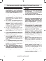
General Power Tool Safety Warnings
Safety Symbols
The definitions below describe the level of severity for each signal word.
Please read the manual and pay attention to these symbols.
This is the safety alert symbol. It is used to alert you to potential personal injury
hazards. Obey all safety messages that follow this symbol to avoid possible injury or
death.
DANGER indicates a hazardous situation which, if not avoided, will result in death or
serious injury.
WARNING indicates a hazardous situation which, if not avoided, could result in death
or serious injury.
CAUTION indicates a hazardous situation which, if not avoided, could result in minor or
moderate injury.

3
General Power Tool Safety Warnings
c. Prevent unintentional starting. Ensure the switch is
in the off-position before connecting to power source
and / or battery pack, picking up or carrying the tool.
Carrying power tools with your finger on the switch or
energizing power tools that have the switch on invites
accidents.
d. Remove any adjusting key or wrench before turning
the power tool on. A wrench or a key left attached to
a rotating part of the power tool may result in personal
injury.
e. Do not overreach. Keep proper footing and balance at
all times. This enables better control of the power tool in
unexpected situations.
f. Dress properly. Do not wear loose clothing or jewelry.
Keep your hair and clothing away from moving parts.
Loose clothes, jewelry or long hair can be caught in
moving parts.
g. If devices are provided for the connection of dust
extraction and collection facilities, ensure these are
connected and properly used. Use of dust collection
can reduce dust-related hazards.
h. Do not let familiarity gained from frequent use of
tools allow you to become complacent and ignore tool
safety principles. A careless action can cause severe
injury within a fraction of a second.
4. Power tool use and care
a. Do not force the power tool. Use the correct power
tool for your application. The correct power tool will
do the job better and safer at the rate for which it was
designed.
b. Do not use the power tool if the switch does not turn it
on and off. Any power tool that cannot be controlled with
the switch is dangerous and must be repaired.
c. Disconnect the plug from the power source and/or
remove the battery pack, if detachable, from the
power tool before making any adjustments, changing
accessories, or storing power tools. Such preventive
safety measures reduce the risk of starting the power tool
accidentally.
d. Store idle power tools out of the reach of children and
do not allow persons unfamiliar with the power tool or
these instructions to operate the power tool. Power
tools are dangerous in the hands of untrained users.
e. Maintain power tools and accessories. Check for
misalignment or binding of moving parts, breakage of
parts and any other condition that may affect the power
tool’s operation. If damaged, have the power tool repaired
before use. Many accidents are caused by poorly
maintained power tools.
f. Keep cutting tools sharp and clean. Properly maintained
cutting tools with sharp cutting edges are less likely to
bind and are easier to control.
g. Use the power tool, accessories and tool bits etc. in
accordance with these instructions, taking into account
the working conditions and the work to be performed.
Use of the power tool for operations different from those
intended could result in a hazardous situation.
h. Keep handles and grasping surfaces dry, clean and
free from oil and grease. Slippery handles and grasping
surfaces do not allow for safe handling and control of the
tool in unexpected situations.
5. Battery tool use and care
a. Recharge only with the charger specified by the
manufacturer. A charger that is suitable for one type
of battery pack may create a risk of fire when used with
another battery pack.
b. Use power tools only with specifically designated
battery packs. Use of any other battery packs may
create a risk of injury and fire.
c. When battery pack is not in use, keep it away from
other metal objects like paper clips, coins, keys,
nails, screws, or other small metal objects that can
make a connection from one terminal to another.
Shorting the battery terminals together may cause
burns or a fire.
d. Under abusive conditions, liquid may be ejected
from the battery, avoid contact. If contact
accidentally occurs, flush with water. If liquid
contacts eyes, additionally seek medical help. Liquid
ejected from the battery may cause irritation or burns.
e. Do not use a battery pack or tool that is damaged or
modified. Damaged or modified batteries may exhibit
unpredictable behavior resulting in fire, explosion or
risk of injury.
f. Do not expose a battery pack or tool to fire
or excessive temperature. Exposure to fire or
temperature above 265 °F may cause explosion.
g. Follow all charging instructions and do not charge
the battery pack or tool outside the temperature
range specified in the instructions. Charging
improperly or at temperatures outside the specified
range may damage the battery and increase the risk of
fire.

4
a. Wear ear protectors when impact drilling. Exposure to
noise can cause hearing loss.
b. Use the auxiliary handle(s). Loss of control can cause
personal injury.
c. Hold the power tool by insulated gripping surfaces,
when performing an operation where the cutting
accessory or fasteners may contact hidden wiring.
Cutting accessory or fasteners contacting a "live" wire
may make exposed metal parts of the power tool "live" and
could give the operator an electric shock.
d. Use clamps or another practical way to secure and
support the workpiece to a stable platform. Holding
the work by hand or against your body leaves it unstable
and may lead to loss of control.
e. Do not drill, fasten or break into existing walls or other
blind areas where electrical wiring may exist. If this
situation is unavoidable, disconnect all fuses or circuit
breakers feeding this worksite.
f. Always wear safety goggles or eye protection when
using this tool. Use a dust mask or respirator for
applications which generate dust.
g. Use thick cushioned gloves and limit the exposure
time by taking frequent rest periods. Vibration caused
by hammer-drill action may be harmful to your hands and
arms.
h. Secure the material being drilled. Never hold it in your
hand or across legs. Unstable support can cause the drill
bit to bind causing loss of control and injury.
i. Disconnect battery pack from tool before making any
assembly, adjustments or changing accessories. Such
preventive safety measures reduce the risk of starting the
tool accidentally.
j. Position yourself to avoid being caught between the
tool or side handle and walls or posts. Should the bit
become bound or jammed in the work, the reaction torque
of the tool could crush your hand or leg.
k. If the bit becomes bound in the workpiece, release the
trigger immediately, reverse the direction of rotation
and slowly squeeze the trigger to back out the bit. Be
ready for a strong reaction torque. The drill body will tend
to twist in the opposite direction as the drill bit is rotating.
l. Do not grasp the tool or place your hands too close
to the spinning chuck or drill bit. Your hand may be
lacerated.
m. When installing a drill bit, insert the shank of the
bit well within the jaws of the chuck. If the bit is not
inserted deep enough, the grip of the jaws over the bit is
reduced and the loss of control is increased.
n. Do not use dull or damaged bits and accessories. Dull
or damaged bits have a greater tendency to bind in the
workpiece.
o. When removing the bit from the tool avoid contact
with skin and use proper protective gloves when
grasping the bit or accessory. Accessories may be hot
after prolonged use.
Safety Rules for Cordless Drill/Drivers
6. Service
a. Have your power tool serviced by a qualified repair
person using only identical replacement parts. This
will ensure that the safety of the power tool is maintained.
b. Never service damaged battery packs. Service of
battery packs should only be performed by the
manufacturer or authorized service providers.
General Power Tool Safety Warnings

5
p. Check to see that keys and adjusting wrenches are
removed from the drill before switching the tool "ON".
Keys or wrenches can fly away at high velocity striking you
or a bystander.
q. Do not run the tool while carrying it at your side. A
spinning drill bit could become entangled with clothing
and injury may result.
Safety instructions when using long
drill bits
a. Never operate at higher speed than the maximum speed
rating of the drill bit. At higher speeds, the bit is likely to
bend if allowed to rotate freely without contacting the
workpiece, resulting in personal injury.
b. Always start drilling at low speed and with the bit tip in
contact with the workpiece. At higher speeds, the bit is
likely to bend if allowed to rotate freely without contacting
the workpiece, resulting in personal injury.
c. Apply pressure only in direct line with the bit and do not
apply excessive pressure. Bits can bend causing breakage
or loss of control, resulting in personal injury.
GFCI and personal protection devices like electrician’s
rubber gloves and footwear will further enhance your
personal safety.
Do not use AC only rated tools with a DC power
supply. While the tool may appear to work, the electrical
components of the AC rated tool are likely to fail and create
a hazard to the operator.
Keep handles dry, clean and free from oil and grease.
Slippery hands cannot safely control the power tool.
Develop a periodic maintenance schedule for your tool.
When cleaning a tool be careful not to disassemble
any portion of the tool since internal wires may be
misplaced or pinched or safety guard return springs may
be improperly mounted. Certain cleaning agents such as
gasoline, carbon tetrachloride, ammonia, etc. may damage
plastic parts.
Ensure the switch is in the off position before
inserting battery pack. Inserting the battery pack into
power tools that have the switch on invites accidents.
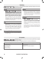
Some dust created by power
sanding, sawing, grinding, drill-
ing, and other construction activities contains chemi-
cals known to cause cancer, birth defects or other repro-
ductive harm. Some examples of these chemicals are:
• Lead from lead-based paints,
• Crystalline silica from bricks and cement and other
masonry products, and
• Arsenic and chromium from chemically-
treated lumber.
Your risk from these exposures varies, depending on how
often you do this type of work. To reduce your exposure
to these chemicals: work in a well ventilated area, and
work with approved safety equipment, such as those dust
masks that are specially designed to filter out microscopic
particles.
THINK SAFETY
SAFETY IS A COMBINATION OF OPERATOR COMMON
SENSE AND ALERTNESS AT ALL TIMES WHEN POWER
TOOLS ARE BEING USED.
Additional Safety Warnings
Safety Rules for Cordless Drill/Drivers

6
The manufacturer is not responsible for radio interference
caused by unauthorized modifications to this equipment.
Such modifications could void the user’s authority to operate
the equipment.
This device complies with Part 15 of the FCC Rules.
Operation is subject to the following two conditions:
1) This device may not cause harmful interference, and
2) This device must accept any interference received,
including interference that may cause undesired
operation.
NOTE! This equipment has been tested and found to comply
with the limits for a Class B digital devices, pursuant to Part
15 of the FCC rules. These limits are designed to provide
reasonable protection against harmful interference in a
residential installation. This equipment generates, uses
and can radiate radio frequency energy and, if not installed
and used in accordance with the instructions, may cause
harmful interference to radio communications. However,
there is no guarantee that interference will not occur in a
particular installation. If this equipment does cause harmful
interference to radio or television reception, which can be
determined by turning the equipment off and on, the user is
encouraged to try to correct the interference by one or more
of the following measures:
• Reorient or relocate the receiving antenna.
• Increase the separation between the equipment and
receiver.
• Connect the equipment into an outlet on a circuit different
from that to which the receiver is connected.
• Consult the dealer or an experienced radio/TV technician
for help.
“Exposure to Radio Frequency (RF) Signals: The wireless
device is a radio transmitter and receiver. It is designed
and manufactured not to exceed the emission limit for
exposure to radio frequency (RF) energy set by the Ministry
of Health (Canada), Safety Code 6. These limits are part of
comprehensive guidelines and established permitted levels
of RF energy for the general population.
These guidelines are based on the safety standards
previously set by international standard bodies. These
standards include a substantial safety margin designed to
assure the safety of all persons, regardless of age and health.
This device and its antenna must not be co-located
or operating in conjunction with any other antenna or
transmitter.
FCC Caution
This device complies with Industry Canada licence-exempt
RSS standard(s). Operation is subject to the following two
conditions:
(1) this device may not cause interference, and
(2) this device must accept any interference, including
interference that may cause undesired operation of the
device.
Industry Canada

7
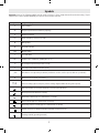
Symbols
Important: Some of the following symbols may be used on your tool. Please study them and learn their meaning. Proper
interpretation of these symbols will allow you to operate the tool better and safer.
Symbol Designation / Explanation
V Volts (voltage)
Ah Amp hour (measurement of battery capacity)
A Amperes (current)
Hz Hertz (frequency, cycles per second)
W Watt (power)
kg Kilograms (weight)
min Minutes (time)
s Seconds (time)
Diameter (size of drill bits, grinding wheels, etc.)
n0No load speed (rotational speed at no load)
n Rated speed (maximum attainable speed)
.../min Revolutions or reciprocation per minute (revolutions, strokes, surface speed, orbits etc. per minute)
0 Off position (zero speed, zero torque...)
1, 2, 3, ...
I, II, III, Selector settings (speed, torque or position settings. Higher number means greater speed)
Infinitely variable selector with off (speed is increasing from 0 setting)
Arrow (action in the direction of arrow)
Alternating current (type or a characteristic of current)
Direct current (type or a characteristic of current)
Alternating or direct current (type or a characteristic of current)
Class II construction (designates double insulated construction tools)
Earthing terminal (grounding terminal)
A
0
A
0
A
0
A
0
A
0
A
0
A
0

8
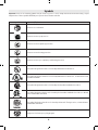
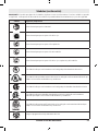
Important: Some of the following symbols may be used on your tool. Please study them and learn their meaning. Proper
interpretation of these symbols will allow you to operate the tool better and safer.
Symbols
Symbol Designation / Explanation
Alerts user to read manual
Alerts user to wear eye protection
Alerts user to wear respiratory protection
Alerts user to wear hearing protection
Alerts user to wear eye, respiratory, and hearing protection
This symbol designates that this tool is listed by Underwriters Laboratories.
This symbol designates that this tool is listed by Underwriters Laboratories, to United States and
Canadian Standards.
This symbol designates that this tool is listed by the Canadian Standards Association.
This symbol designates that this tool is listed by the Canadian Standards Association, to United
States and Canadian Standards.
This symbol designates that this tool is listed by the Intertek Testing Services, to United States
and Canadian Standards.
Designates Li-ion battery recycling program

9
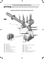
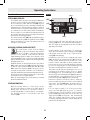
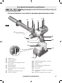
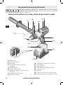
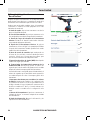
Functional Description and Specifications
Disconnect battery pack from tool before making any assembly, adjustments or changing
accessories. Such preventive safety measures reduce the risk of starting the tool accidentally.
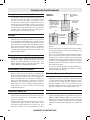
Cordless Drill Drivers and Cordless Hammer Drills
(1)
(7)
(16)
(13) (12)
(10)
(9)
(17)
(11)
(5)
(14)
(15)
(2)
(3) (4)
(6)
(8)
(1) Keyless chuck
(2) Depth gauge
(3) Auxiliary handle
(4) Wing bolt for depth stop adjustment
(5) Adjustable clutch
(6) Rapid Mode Selector
(7) Gear shifter/speed range selector
(8) LED for leveling function
(9) Handle (insulated gripping surface)
(10) Connectivity module compartment
(11) Belt clip
(12) Battery pack
(13) Battery pack release button
(14) User Interface
(15) Bit holder
(16) Forward/reversing lever and trigger lock
(17) Variable speed trigger switch
FIG. 1

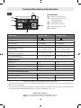
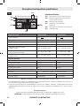
10
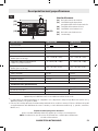
Optimized for AMPShare 18V with Max performance from ≥ 8Ah
A The mobile terminal devices must be compatible with Bluetooth® Low Energy devices (version 4.1) and support the
Generic Access Profile (GAP).
B The signal range may vary greatly depending on external conditions. The Bluetooth® range may be significantly weaker
inside closed rooms and through metallic barriers (e.g. walls, shelving units, cases, etc.).
Model number GSR18V-1330C GSB18V-1330C
Voltage rating 18 V
A
0
18 V
A
0
No load speed 1 n0 0-550/min n0 0-550/min
No load speed 2 n0 0-2200/min n0 0-2200/min
Beats per minute NA 30,000 bpm
Permitted battery temperature
during charging +32…+113°F (0…+45C) +32…+113°F (0…+45C)
Permitted ambient temperature
during operation and storage -4…+122°F (-20…+50C) -4…+122°F (-20…+50C)
Recommended ambient
temperature during charging +32…+95°F (0...+35°C) +32…+95°F (0...+35°C)
Maximum Capacities
Chuck size 1/2" 1/2"
Drilling mild metal 5/8" 5/8"
Drilling wood 5-7/8" 5-7/8"
Drilling masonry NA 3/4"
Data Transmission (GCY42 installed)
Bluetooth® Bluetooth® 4.1 (Low Energy)A
Signal interval, approx. 8 s 8 s
Signal range maximum 98ftBmaximum 98ftB
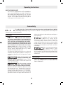
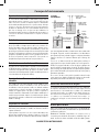
Functional Description and Specifications
Battery Packs / Chargers:
Please refer to the battery/charger list, included with your tool.
NOTE: For tool specifications refer to the nameplate on your tool.
(19)
(18)
(20)
(22)
(23)
(21)
User Interface
(18) Button for leveling function
(19) LED for preset slope angle of
the leveling function
(20) Status indicator LED
(21) LED for KickBack control
(22) Button for KickBack control
(23) Worklight
FIG. 2

11
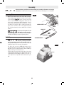
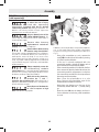
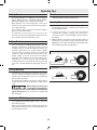
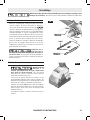
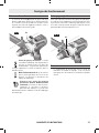
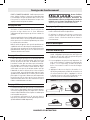
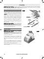
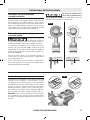
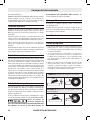
Inserting Bits
Move reverse switch lever to the center “OFF” position.
Remove battery pack and turn the mode selector switch
to the drilling position. Rotate the chuck
sleeve counter-clockwise viewing from chuck end, and
open chuck to approximate drill bit diameter. Insert a
clean bit up to the drill bit flutes for small bits, or as far
as it will go for large bits. Close chuck by rotating the
chuck sleeve clockwise and securely tighten by hand
(Fig. 3). Move forward / reverse switch lever to desired
position.
Do not use the power of the
drill while grasping chuck to
loosen or tighten bit. Friction burn or hand injury is
possible if attempting to grasp the spinning chuck.
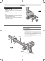
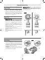
Belt Clip
When the tool is attached to
the belt, position yourself to
avoid entanglement with surrounding objects.
Unexpected entanglement could cause the tool to fall
resulting in injury to the operator or bystanders.
The belt clip accessory (11) will allow you to
conveniently attach your tool to your belt. This feature
will allow you to have both hands free when climbing a
ladder or moving to another work area.
The belt clip can be attached to either side of the tool by
securing it with a mounting screw. Always make sure you
securely tighten the mounting screw before use (Fig. 4).
To use clip, turn tool upside down and attach to your
belt.
FIG. 4
Assembly
Disconnect battery pack from tool before making any assembly, adjustments or changing
accessories. Such preventive safety measures reduce the risk of starting the tool accidentally.
FIG. 3
CHUCK SLEEVE
DRILL BIT
BIT HOLDER
SCREWDRIVER BIT
CLOSE
OPEN

12
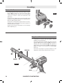
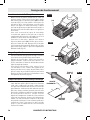
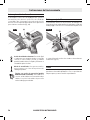
4X Bit Tip Holder
Store only bit tips in the on-
tool bit holder. Longer bits
could interfere with proper tool operation and result in
user injury.
The four piece bit tip holder (15) can be used for
convenient on tool storage of your most commonly used
bits.
When mounting bit holder accessory, mount on the side
of the drill opposite the belt clip.
Always make sure you securely tighten the mounting
screw before use. (Fig. 5).
A
B
D
C
E
HAND
GRIP
SLEEVE
COLLAR
FIG. 6
(15)
FIG. 5
Assembly
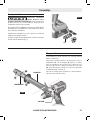
Auxiliary Handle
The tool must be supported with the auxiliary handle
during operation.
To mount the auxiliary handle on the tool loosen the
hand grip (A). Pull on the sleeve (B) and slide the
collar on to the tool as shown (C). Swivel the handle
to desired position (D). Secure the handle in place by
tightening the hand grip (E). See Fig. 6.
To remove the handle for transportation or storage
reverse the steps above.

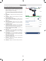
13
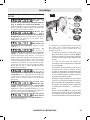
GCY42 Connectivity module installation
(sold separately)
To reduce the risk of injury
read the operating
instructions included with Bosch GCY42
connectivity module. Operating instructions for
GCY42 connectivity module include important
information not covered in this manual.
Only use Button/coin cell 3V
lithium CR2032 battery. Do
not use any other button/coin cells or other forms of
electrical power supply.
Ensure that battery
replacement is carried out
properly. There is a risk of explosion.
Chemical Burn Hazard. Keep
batteries away from children.
This product contains a lithium button/coin cell battery.
If a new or used lithium button/coin cell battery is
swallowed or enters the body, it can cause severe
internal burns and can lead to death in as little as 2
hours. If you think a battery might have been swallowed
or placed inside any part of the body, seek immediate
medical attention.
Always completely secure the
connectivity module
compartment. If the connectivity module compartment
does not close securely, stop using the product, remove
the battery, and keep it away from children.
When discarding batteries,
insulate the ‘+’ and ‘–’
terminals with insulating tape. When disposed of
improperly, lithium batteries may short, causing them to
become hot, burst or ignite.
Never dispose of the batteries
in a fire or expose to high
heat. The batteries may explode.
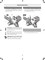
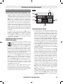
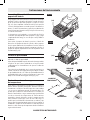
If GCY42 connectivity module is not purchased with the
tool, or if the replacement of the module or the battery
becomes necessary, please follow this procedure (see
Fig. 7):
- Using a flat screwdriver or a coin, remove the
cover (10) from the side of the handle, by turning
it 1/4 turn counter-clockwise.
- If the tool is already equipped with the
connectivity module, remove the battery a, but
do not remove the connectivity module b.
- If the connectivity module is installed for the first
time, remove the plastic placeholder c from the
connectivity module compartment, and place
the connectivity module b in the compartment
observing correct orientation.
Note: Store the placeholder c in a safe
place. Reinsert the placeholder again if the
communications module is removed.
- Next place new battery a on the top of the
connectivity module with the “+” polarity facing
up.
- Place the cover 10 over the battery and turn it
¼-turn clockwise to lock using a flat screwdriver
or a coin.
a
b
(10)
c
FIG. 7
Assembly
(10)

14
Variable Speed Controlled
Trigger Switch
Your tool is equipped with a variable speed trigger
switch. The tool can be turned "ON" or "OFF" by
squeezing or releasing the trigger. The speed can be
adjusted from the minimum to maximum nameplate
RPM by the pressure you apply to the trigger. Apply
more pressure to increase the speed and release
pressure to decrease speed (Fig. 1).
Forward/Reversing Lever &
Trigger Lock
After tool use, lock trigger in
“OFF” position to help
prevent accidental starts and accidental discharge.
Your tool is equipped with a forward/
reversing lever and trigger lock (16) located above the
trigger (Fig. 8). This lever was designed for changing
direction of rotation of the bit, and for locking the
trigger in an “OFF” position.
For forward rotation, (with chuck pointed away from
you) move the lever to the far left (Fig. 8).
For reverse rotation, move the lever to the far right
(Fig. 8).
To activate trigger lock, move lever to the center off
position.
Do not change direction of
rotation until the tool comes to a
complete stop. Shifting during rotation of the chuck can
cause damage to the tool.
Operating Instructions
(16)
(16)
FIG. 8
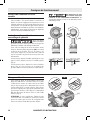
Gear Shifting
Your tool is equipped with two separate gear ranges,
low gear 1 and high gear 2. Low gear provides high-
torque and slower drilling speeds for heavy duty work or
for driving screws. High gear provides faster speeds for
drilling lighter work. To change speeds slide switch (7),
to the high 2 or low position 1 (Fig. 9).
ATTENTION: If your tool appears to be running, but the
chuck will not turn, check to make sure the gear shifter
is pushed fully into desired setting. (7)
FIG.9

15
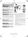
Rapid Mode Selector
The rapid mode selector (6) allows the tool to be set for
various drilling or driving applications. Turn the rapid
mode selector right or left depending on the below
applications (Fig. 10).
Drill only action: This mode will lock up the clutch
to permit drilling and driving heavy duty work, and
also will enable bits to be changed quickly and
easily in the keyless chuck.
Driver mode: To drive screws, nuts, and bolts
with use of the adjustable clutch settings to limit
torque and power output to prevent over driving
and fastener/workpiece damage..
Drill with hammer action (GSB18V-1330C
Model only): For drilling in concrete, asphalt,
tile or other similar hard materials. The hammer
drill position overrides the clutch for drilling.
Adjustable Clutch
Your tool features 25 clutch settings. Output torque will
increase as the clutch ring (5), is rotated from 1 to 25.
The tool will stop rotating as soon as the set torque is
reached during operation (Fig. 11).
Brake
When the trigger switch is released it activates the
brake to stop the chuck quickly. This is especially useful
in the repetitive driving and removal of screws.
(5)
FIG. 11
FIG. 10
(6)
Operating Instructions

16
Inserting & Releasing Battery Pack
To insert battery pack: Set Forward/ Reversing lever
to the center (off position). Slide charged battery pack
(12) into the housing until the battery pack locks into
position (Fig. 12).
To check if the battery is locked in place, lightly pull the
battery in the opposite direction. If the battery moves,
do not use the tool and repeat the insertion procedure
until the battery is locked in place and does not slide
backwards.
Your tool is equipped with a secondary locking latch to
prevent the battery pack from completely falling out of
the handle, should it become loose due to vibration.
To remove battery pack: press the battery pack
release button (13) and slide the battery pack towards
the front of the tool. Press the battery pack release
button again and slide the battery pack completely out
of tool housing (Fig. 13).
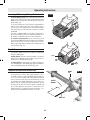
Depth Gauge
Your drilling depth can be pre-set and/or repeated by
using the depth gauge.
Setting depth: After the auxiliary handle is installed,
make sure the drill bit has been fully inserted into the
chuck before setting the depth gauge.
To adjust depth: turn the wing nut counter-clockwise to
loosen depth gauge, slide depth gauge to desired depth X,
and securely tighten wing nut clockwise (Fig. 14).
Temperature Overload Protection
Avoid using battery operated tools continuously,
for long periods of time, while subjecting the tool to
overload conditions, such as drilling with large diameter
accessories into hard materials. Using battery powered
tools at extreme loads, may cause the battery to exceed
its allowable operating temperature range. When the
battery exceeds normal operating temperature caused
by overload, the speed of the tool may be reduced and
the tool may appear to lose power. To regain the tool's
full performance, the battery must be allowed to cool,
until the operating temperature returns to normal.
(13)
FIG. 13
FIG. 14
DEPTH
GAUGE
X
WING
NUT
DRILL BIT
Operating Instructions
FIG. 12
(12)

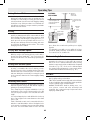
17
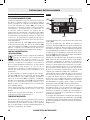
User Interface
STATUS INDICATOR LED
The LED bar at the top of the user interface illuminates
in various colors to help the user identify the status of
the tool. When the status indicator LED (20) is green
the tool and battery pack are operating normally and
temperatures are ok. If the indicator changes to yellow it
means that the tool or battery temperatures have risen
to a critical level. It is best to back off the load and give
the tool a chance to cool down. If the indicator turns red
the tool will shut off to protect itself and/or the battery
pack from an overheating situation.
The status indicator LED (20) will also blink blue when
the leveling function (18) or KickBack Control (22)
buttons are held for 7 seconds. This will reset the tool
settings to factory default.
KICKBACK CONTROL (RAPID SHUT-OFF)
To ensure better control of the tool during
operation, this tool is design to shut-off while
in use if a sudden or unexpected bind up
situation occurs. Bind up occurs when the bit gets
jammed during operation, which forces the bit to stop
spinning abruptly. If this occurs, the tool will shut down
and the KickBack Control will be indicated by flashing
LED lights on the tool.
KickBack Control can be turned off by the user. Button
(22) on the user interface (14) will toggle the feature
on and off. Status is indicated with "On" and "Off" LEDS
(21) on the User Interface (14). If the power tool is
not used for longer than 5 minutes, or if the battery is
removed, KickBack Control automatically turns back on.
Please note that the indicator light may not be visible
from all directions or in bright sunlight.
When the switch trigger is pressed, operator is notified
about the KickBack Control.
LEVELING FUNCTION
With the leveling function, a slope angle can be
preselected for power tool detection and indication
during work. This means it is possible to drill or
screw perpendicular to sloped surfaces, for example.
The leveling function is con-trolled via the user
interface(14).
Select an angle (45°, 60°, user-defined) on the user
interface(14). Note: The default user-defined angle is
90°. This angle can be adjusted via the Bosch Toolbox
app using connectivity
module GCY42 (sold separately). To adjust the
angle, press the button for the leveling function(18)
repeatedly until the LED of the required slope
angle(19) starts flashing.
In addition to the LED of the required slope angle
(19), the LED of the leveling function(8) also starts
to flash yellow. Now position the power tool on the
reference surface and hold it as still as possible. Note:
If the power tool is not held still during the initiating
process, the initiating process will automatically end
after 10seconds and the last set value is restored.
The power tool will start the initiating process once it
is positioned. The reference surface is set as o° during
the initiating process. The initiating process is complete
when the LED of the leveling function(8) lights up green
for approximately 1second and then goes out, and the
LED of the slope angle(19) lights up continuously.
Remove the power tool from the surface. Align the
power tool with the reference surface at the required
slope angle. The LED(20) lights up yellow if the tool
angle lies in the range +/-10° from the preset slope
angle.
If a tool angle is within +/-3° of the preset slope
angle, the LED (8) lights up green. To end the
leveling function, press the button for the leveling
function(18) repeatedly until none of the LEDs for
angle selection(19) are lit up (45° 60° User-defined
Off). The set angle and reference surface are saved
even when changing the battery or when waking up the
power tool from sleep mode.
Operating Instructions
(19)
(18)
(20)
(22)
(23)
(21)
FIG. 15

18
Connectivity
Bluetooth®
Do not use the power tool with
Bluetooth® in the vicinity of
gas stations, chemical plants, areas where there is
danger of explosion and areas subject to blasting. Do
not use the power tool with Bluetooth® in airplanes.
Do not use the power tool with Bluetooth® in the
vicinity of medical devices. Avoid operation in the
direct vicinity of the human body over longer
periods of time. When using the power tool with
Bluetooth®, interference with other devices and
systems, airplanes and medical devices (e.g., cardiac
pacemakers, hearing aids) may occur.
The Bluetooth® word mark and logos are registered
trademarks owned by Bluetooth SIG, Inc. and any use of
such marks by Robert Bosch Tool Corporation is under
license.
Follow all instructions and
warnings provided by your
Bluetooth® device manufacturer. Failure to follow
recommended procedures could result in personal
injury or property damage.
Exercise extreme caution
when using Bluetooth®
devices to control or change power tool functions.
Operation of the device may be in a different area than
the paired power tool. Paired devices may have
functionality which allows timed event programming,
including automatically powering on (e.g. flood light).
Depending upon the power tool, these unattended
operations or function changes without direct line of
sight to the paired tool could result in personal injury or
property damage.
Always check tool settings
before use. Settings may be
different than when the tool was last used. The
connectivity module enables transfer of data and
settings based on Bluetooth® wireless technology. With
module installed, select tool settings may be changed
remotely by a paired Bluetooth® device and user
installed app.
The connectivity module GCY42
is equipped with a radio
interface. Local operating restrictions, e.g. in military
sites or hospitals, are to be observed. Transmitters have
demonstrated an ability to unintentionally interfere with
other devices.
Think Safety
SAFETY IS A COMBINATION OF OPERATOR COMMON
SENSE AND ALERTNESS AT ALL TIMES WHEN THE
TOOL IS BEING USED.
To reduce the risk of injury read the operating instructions included with Bosch GCY42
connectivity module. Operating instructions for GCY42 connectivity module include important
information not covered in this manual.
BUILT IN LED WORK LIGHT
Your tool is also equipped with an LED light (23) that
turns on automatically when the switch is activated, for
better visibility when drilling/ driving (Fig. 15). The light
turns off automatically a short time after the trigger is
released. You can adjust this time frame using Bosch
Tool Box app. See “Connectivity” section.
Operating Instructions

19
Using ‘Bosch Toolbox’ app
After pairing your tool with a mobile device you can
adjust certain functions or check the status of the
power tool using Bosch Toolbox app.
Every time you change any setting the tool will confirm
the changes by flashing the blue LED status indicator
light.
A. Help button – tapping this button will bring up help
screen.
B. Tool photo – tapping on the photo will let you customize
the photograph of the tool.
C. Power tool battery charge status – the number of green
‘batteries’ indicates the estimated charge level for the
battery pack.
D. Power tool nickname – tapping on the ‘pencil’ icon will let
you customize the tool nickname. You can also do it when
changing the tool photo.
E. Connection status bar – displays the connection (signal)
strength indicated by vertical bars. You can use toggle
switch to disconnect the tool from your mobile device.
F. Electronic Angle Detection (EAD) – you can set a
custom user angle.
G. Work Light – you can set the brightness and number of
seconds that the LED worklight stays on after the trigger
switch of the tool is released.
H. User Interface – you can set the brightness and number
of seconds that the user interface stays on after the trigger
switch of the tool is released.
I. Factory Reset toggle switch – you can reset tool settings
back to factory default settings.
J. Tool alerts – tapping the ‘alerts triangle’ will display any
alerts received from the tool.
K. Info button – displays tool information and specifications.
GSB18V-1330C
GSB18V-1330C A
B
C
D
E
F
G
H
I
K J
Connectivity

20
Driving Nuts and Bolts
Variable speed control must be used with caution for
driving nuts and bolts with socket set attach ments. The
technique is to start slowly, increasing speed as the nut
or bolt runs down. Set the nut or bolt snugly by slowing
the drill to a stop. If this procedure is not followed, the
tool will have a tendency to torque or twist in your hands
when the nut or bolt seats.
Drilling
You will extend the life of your bits and do neater
work if you always put the bit in contact with the work
before pulling the trigger. During the oper a tion, hold
the tool firmly and exert light, steady pressure. Too
much pressure at low speed will stall the tool. Too
little pressure will keep the bit from cutting and cause
excess friction by sliding over the surface. This can be
damaging to both tool and bit.
Drilling with Variable Speed
The variable speed trigger allows you to slowly increase
RPM. By using a slow starting speed, you are able to
keep the bit from “wander ing”. You can increase the
speed as the bit “bites” into the work by squeezing the
trigger.
Driving with variable speed
Variable speed drills will double as a power screwdriver
by using a screwdriver bit. Prior to driving screws,
pilot and clearance holes should be drilled. Place the
threaded end of the screw in the pilot or clearance hole
and start driving the screw slowly, increasing the speed
as the screw runs down. Set the screw snugly by slowing
to a stop.
Fastening with Screws
The procedure shown in Fig. 16 will enable you to fasten
materials together using your drill without stripping,
splitting or separating the material.
First, clamp the pieces together and drill the hole 2/3
the diameter of the screw. If the material is soft, drill
only 2/3 the proper length. If it is hard, drill the entire
length.
Second, unclamp the pieces and drill the hole in the top
piece of wood again to the same diameter as the shank
of the screw.
Third, if flat head screw is used, countersink the hole to
make the screw flush with the surface. Realign the holes
on the two pieces and apply even pressure when driving
the screw. The screw shank clearance hole in the first
piece allows the screw head to pull the pieces tightly
together.
The adjustable screw drill accessory will do all of these
operations quickly and easily. Screw drills are available
for screw sizes No. 6, 8, 10 and 12.
Electronic Angle Detect
Orientation of the tool while calibrating the surface will
determine the reference for the angle. On a vertical
wall, if the tool is calibrated with the chuck pointing
upward, a target angle will be established in an upward
orientation (e.g. +45°). If the tool is calibrated with
the chuck pointing downward, a target angle will be
established in a downward orientation (e.g. -45°).
Drill Bits
Always inspect drill bits for excessive wear. Use only bits
that are sharp and in good condition.
TWIST BITS: Available with straight and reduced shanks
for wood and light duty metal drilling. High speed bits
cut faster and last longer on hard ma terials.
CARBIDE TIPPED BITS: Used for drilling stone, con-
crete, plaster, cement and other unusually hard
nonmetals. Use continuous heavy feed pres sure when
employing carbide tip bits.
2. Drill same
diameter as
screw shank.
3. Countersink same
diameter as screw
head.
1. Drill 2/3 diameter and 2/3
of screw length for soft
materials, full length for
hard materials.
Adjustable
Screw
Drill
Screw
Apply a slight
even pressure
when driving
screws.
FASTENING
WITH SCREWS
Operating Tips
La page charge ...
La page charge ...
La page charge ...
La page charge ...
La page charge ...
La page charge ...
La page charge ...
La page charge ...
La page charge ...
La page charge ...
La page charge ...
La page charge ...
La page charge ...
La page charge ...
La page charge ...
La page charge ...
La page charge ...
La page charge ...
La page charge ...
La page charge ...
La page charge ...
La page charge ...
La page charge ...
La page charge ...
La page charge ...
La page charge ...
La page charge ...
La page charge ...
La page charge ...
La page charge ...
La page charge ...
La page charge ...
La page charge ...
La page charge ...
La page charge ...
La page charge ...
La page charge ...
La page charge ...
La page charge ...
La page charge ...
La page charge ...
La page charge ...
La page charge ...
La page charge ...
La page charge ...
La page charge ...
La page charge ...
La page charge ...
-
 1
1
-
 2
2
-
 3
3
-
 4
4
-
 5
5
-
 6
6
-
 7
7
-
 8
8
-
 9
9
-
 10
10
-
 11
11
-
 12
12
-
 13
13
-
 14
14
-
 15
15
-
 16
16
-
 17
17
-
 18
18
-
 19
19
-
 20
20
-
 21
21
-
 22
22
-
 23
23
-
 24
24
-
 25
25
-
 26
26
-
 27
27
-
 28
28
-
 29
29
-
 30
30
-
 31
31
-
 32
32
-
 33
33
-
 34
34
-
 35
35
-
 36
36
-
 37
37
-
 38
38
-
 39
39
-
 40
40
-
 41
41
-
 42
42
-
 43
43
-
 44
44
-
 45
45
-
 46
46
-
 47
47
-
 48
48
-
 49
49
-
 50
50
-
 51
51
-
 52
52
-
 53
53
-
 54
54
-
 55
55
-
 56
56
-
 57
57
-
 58
58
-
 59
59
-
 60
60
-
 61
61
-
 62
62
-
 63
63
-
 64
64
-
 65
65
-
 66
66
-
 67
67
-
 68
68


Bosch GSB18V-1330CB14 Mode d'emploi
- Catégorie
- Outils électroportatifs
- Taper
- Mode d'emploi
dans d''autres langues
Documents connexes
-
Bosch GSB18V-535CB15 Manuel utilisateur
-
-
 Bosch Tools GDX18V-1800CB25 Le manuel du propriétaire
-
Bosch GSR18V-190 Manuel utilisateur
-
-
Bosch Power Tools CLPK237-181 Manuel utilisateur
-
Bosch DDBB180-02-RT Mode d'emploi
-
Bosch Power Tools HDS182-01L Manuel utilisateur
-
Bosch Power Tools HDS181A-02 Manuel utilisateur
