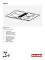
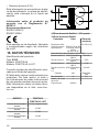
Smart FSM 709 HI Manuel utilisateur
- Catégorie
- Plaques de cuisson
- Taper
- Manuel utilisateur

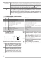
EN User manual
DE Bedienungsanleitung
FR Manuel d’utilisation
NL Gebruikershandleiding
IT Istruzioni per l‘uso
ES Manual del usuario
PT Manual do utilizador
SV Bruksanvisning
FI Käyttöohjeet
NO Brukerveiledning
FSM 709 HI
FSM 709 HI LL KIT
SMART

EN
.................................................................................................................................. 3
DE
.................................................................................................................................. 19
FR
.................................................................................................................................. 37
NL
.................................................................................................................................. 55
IT
.................................................................................................................................. 73
ES
.................................................................................................................................. 90
PT
..................................................................................................................................107
SV
..................................................................................................................................125
FI
..................................................................................................................................141
NO
..................................................................................................................................158

EN
1. SAFETY INFORMA-
TION
For your own safety and
correct operation of the
appliance, please read
this manual carefully be-
fore installation and oper-
ation. Always keep these
instructions together with
the appliance, even if it is
sold or transferred to third
parties. It is important that
users know all the appli-
ance's operating and
safety characteristics.
These hobs have induc-
tion systems that comply
with the requirements of
EMC standards and with
the EMF directive, and
they should not interfere
with other electronic
devices. Pacemaker
wearers and those using
other electronic implants
must consult their doctor
or the manufacturer of the
implanted device to as-
sess whether or not it is
sufficiently resistant to in-
terference.
Electrical connections
must be performed by a
trained technician. Before
making the electrical con-
nection, please read the
section on ELECTRICAL
CONNECTION.
For appliances with a power
supply cable, the terminals or
section of wire between the
cable anchor point and the ter-
minals must be laid out that they
allow the live wire to be extrac-
ted before the earth wire, if it
comes loose.
• The manufacturer cannot be
held responsible for any dam-
age resulting from incorrect or
inadequate installation.
• Check that the mains power
supply corresponds to the
one indicated on the rating
plate affixed to the inside of
the product.
• The cut-out devices must be
installed in the fixed system
according to wiring system
regulations.
• For Class I appliances, check
that the domestic power sup-
ply has a suitable earthing
connection.
• Connect the suction hood to
the flue using a suitable pipe.
Refer to the purchasable ac-
cessories indicated in the in-
stallation manual (for circular
pipes: minimum diameter 120
mm). The length of the dis-
charge piping must be as
short as possible.
• Connect the product to the
mains using an omnipolar
switch.
• The air venting regulations
must be complied with.
• Never connect the suction ap-
pliance to ducts carrying com-
bustion fumes (heaters, fire-
places, etc.).
• If the suction hood is used
alongside non-electrical ap-
pliances (e.g. appliances with
3

gas burners), it is necessary
to guarantee a sufficient level
of ventilation in the room, to
prevent any exhaust back-
flow. When the cooking appli-
ance is used together with
other appliances using non-
electrical power sources, the
negative pressure in the room
must not exceed 4 Pa, to pre-
vent the fumes being sucked
back into the room by the
cooking appliance.
• The air must not be dis-
charged into a pipe that is also
used as a flue for appliances
powered by gas or other fuels.
• If the power cable is dam-
aged, it must be replaced by
the manufacturer, an author-
ised service centre or a quali-
fied technician, to avoid any
risk of danger.
• Connect the appliance plug to
a socket that complies with
current regulations and is in
an accessible area.
• As regards the technical and
safety measures to be taken
for exhausting of fumes, it is
important that the regulations
set by local authorities be fol-
lowed carefully.
WARNING: Remove the
protective films before in-
stalling the appliance.
• Only use the screws and
other hardware elements
supplied with the appliance.
WARNING: Failure to in-
stall the screws or fixing
devices as described in
these instructions may
lead to a risk of electric
shocks.
• Cleaning and maintenance
must not be carried out by
children, unless they are su-
pervised by an adult.
• Children must be supervised
to ensure that they do not play
with the appliance.
• This appliance must not be
used by persons (including
children) with limited phys-
ical, sensory or mental abilit-
ies, or by inexperienced or un-
trained persons, unless
closely supervised and in-
structed in the safe use of the
appliance by a person re-
sponsible for their safety.
• This appliance may be used
by children over the age of
eight and by persons with lim-
ited physical, sensory or men-
tal abilities or with insufficient
experience and knowledge,
provided they are closely su-
pervised and instructed on
the safe use of the appliance
and on the dangers that it in-
volves. Do not allow children
to play with the appliance.
WARNING: The appli-
ance and its accessible
parts become extremely
hot during use.
Take great care not to touch the
heating elements.
Keep children under 8 years of
age well away from the appli-
4

ance, unless they are under
constant supervision.
• Clean and/or replace the fil-
ters after the period indicated
(danger of fire). See the para-
graph on Cleaning and main-
tenance.
• Always guarantee adequate
ventilation of the room when
the appliance is used in con-
junction with other appliances
powered by gas or other fuels
(this does not apply to appli-
ances that only recirculate the
air within the room).
WARNING: If the surface
shows any signs of cracking,
turn the appliance off to prevent
any risk of electric shock.
• Do not turn the device on if the
surface is cracked or any
damage is visible in the thick-
ness of the material.
• Do not touch the appliance if
your hands or body are wet.
• Do not use steam appliances
to clean the product.
• Do not rest metal objects such
as knives, forks, spoons and
pan lids on the surface of the
hob, as they might overheat.
• Use the relevant control to
turn the hob off after use; do
not rely on the pan sensors.
WARNING: Unsupervised
cooking on a hob using oil and
grease may be dangerous and
could cause a fire. NEVER at-
tempt to put flames out with wa-
ter. Turn the appliance off and
suffocate the flames by cover-
ing them with a pan lid or a fire
blanket, for example.
WARNING: The cooking pro-
cess must be supervised. A
short cooking process must be
constantly monitored.
• The appliance is not designed
to be started using an external
timer or a separate remote
controlled system.
WARNING: Danger of fire: do
not place objects on the cooking
surfaces.
• The appliance must be in-
stalled to allow it to be cut off
from the electrical power sup-
ply with a contact opening (3
mm) that ensures complete
disconnection under over-
voltage category III condi-
tions.
• The appliance must never be
exposed to the elements
(rain, sun).
• Ventilation of the appliance
must comply with the manu-
facturer’s instructions.
• Keep the packaging away
from children and animals.
• Kitchen hoods and other
cooking fume extractors can
affect the safe operation of
appliances which burn gas or
other fuels (including those in
other rooms) due to the back-
flow of combustion gases.
These gases can cause car-
bon monoxide poisoning.
After installing a kitchen ex-
tractor hood or any other
cooking fume extractor, make
sure that the gas appliances
are tested by a certified tech-
nician to guarantee that there
5

is no backflow of combustion
gases.
2. USE
• The suction hood has been designed
solely to eliminate cooking fumes dur-
ing domestic use.
• Never use the appliance for purposes
other than those for which it has been
designed.
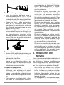
• Deep fryers must be continuously
monitored during use: overheated oil
could catch fire.
• Do not operate the appliance using
an external timer or separate remote
controlled system.
• The appliance must never be in-
stalled behind a decorative door, to
prevent it from overheating.
• Never stand on the appliance, as this
may damage it.
• Do not rest hot pots and pans on the
frame, as this may damage the silic-
one seals.
• Do not cut or prepare foodstuffs on
the surface and do not drop hard ob-
jects onto it. Do not drag pans or
plates over the surface.
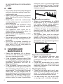
3. CLEANING AND
MAINTENANCE
• Switch the appliance off or discon-
nect it from the electricity supply be-
fore any maintenance work.
• If the Activated Charcoal odour filter
is not supplied, follow the instructions
provided with the kit for both the re-
generation procedure and the re-
placement times.
• If the Activated Charcoal odour filter
is supplied and is of type (U) (refer to
the assembly instructions) it can be
regenerated. The Activated Charcoal
odour filter can be washed and re-
generated every 3-4 months (or more
frequently if the hood is subject to in-
tensive use), up to a Max. of 8 regen-
eration cycles (in case of particularly
intensive use it is recommended that
you do not exceed 5 cycles). To order
a new “U” filter, please contact the as-
sistance service.
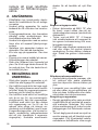
Regeneration procedure:
• Wash in the dishwasher at a MAX
temperature of 70° or hand wash in
hot water without using abrasive
sponges (do not use detergents!).
• Dry in the oven at a MAX temperature
of 70° for 2 hours (it is advisable to
carefully read the user manual and
the assembly instructions of the oven
you own).
• The grease filters must be cleaned
every 2 months of use, or more fre-
quently in the case of particularly in-
tensive use. They can be washed in a
dishwasher. Do not wash the grilles in
the dishwasher. (Z).
General recommendations
• Never use abrasive sponges, wire
wool, hydrochloric acid or other
products that might scratch or mark
the surface.
• Foods that accidentally fall or settle
on the surface, on the functional or
aesthetic elements of the hob must
not be consumed.
Cleaning the device
• Clean the hob after each use to pre-
vent any food residues from carbon-
ising. It is much harder work to re-
move encrusted and burnt-on dirt.
• For day-to-day dirt, use a soft cloth
or sponge and a suitable detergent.
6

Follow the manufacturer’s recom-
mendations regarding detergents to
be used. The use of protective deter-
gents is recommended.
• Remove encrusted dirt, for example
milk that has overflowed during boil-
ing, using a scraper pad suitable for
vitreous ceramic, while the hob is still
hot. Follow the manufacturer’s re-
commendations regarding scraper
pads to be used.
• Remove food containing sugar, for
example jam that has spilt during
cooking, using a scraper pad suitable
for vitreous ceramic, while the hob is
still hot. If you do not, the residue may
damage the vitreous ceramic surface.
• Remove any melted plastic using a
scraper pad suitable for vitreous
ceramic, while the cooker hob is still
hot. If you do not, the residue may
damage the vitreous ceramic surface.
• Remove limescale using a small
amount of limescale remover solu-
tion, for example vinegar or lemon
juice, once the cooker hob has cooled
down. Then, clean again with a damp
cloth.
4. INSTALLATION
REQUIREMENTS
The installation process must comply
with the laws, ordinances, directives
and standards (electrical safety rules
and regulations, proper recycling in ac-
cordance with the regulations, etc.) in
force in the country of use!
• Do not use silicon sealant between
the appliance and the worktop. The
cooker hob is designed to be fitted
flush with the kitchen worktop, on a
kitchen unit with a width of 600 mm or
more.
• If the appliance is mounted on flam-
mable materials, the guidelines and
regulations relating to low voltage in-
stallations and fire prevention must
be followed strictly.
• For built-in units, the components
(plastic materials and veneered
wood) must be mounted with heat-
resistant adhesives (min.100°C): the
use of unsuitable materials and ad-
hesives can cause deformation and
detachment.
• The kitchen unit must have sufficient
space to allow for electrical connec-
tion of the device. Wall-mounted units
above the device must be installed at
a sufficient distance to leave the
space required to work in comfort.
• The use of decorative hardwood bor-
ders around the worktop behind the
device is allowed, provided the min-
imum distance always complies with
the indications provided in the install-
ation drawings.
• The minimum distance between the
fitted device and the rear wall is indic-
ated in the installation drawing for the
flush-fitted device (150 mm for the
side wall, 40 mm for the rear wall and
500 mm for any wall-mounted units
above it).
• To prevent infiltration of liquids
between the edge of the cooker hob
and the worktop, fit the adhesive seal
supplied along the whole outer edge
of the cooker hob prior to installation.
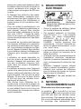
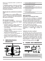
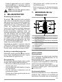
5. ELECTRICAL
CONNECTIONS
WARNING: All electrical connec-
tions must be carried out by an au-
thorised installer.
• Follow the connection diagram (un-
derneath the product).
• This appliance has a Y-type connec-
tion. We recommend using an
H05V2V2-F power cable measuring 5
x 2.5 mm², SINGLE AND TOW-
PHASE connection: minimum wire
section: 2.5 mm². External cable dia-
meter: min 8 mm - max 12 mm.
7

• The connection terminals can be ac-
cessed by removing the junction box
cover.
• Check that the domestic power sup-
ply characteristics (voltage, max-
imum power and current) are compat-
ible with those of the appliance.
• Connect the appliance as outlined in
the installation manual (in compliance
with the standard supply voltages in
force under national law).
Attention! Do not weld any of the
cables!
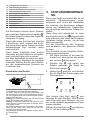
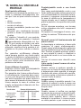
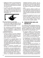
6. ENVIRONMENTAL
ASPECTS
Disposal of household appliances
The symbol on the product or pack-
aging indicates that the product must
not be disposed of with normal domestic
waste. The product must be disposed of
at a specialist recycling centre for elec-
trical and electronic components. By en-
suring that this product is disposed of
correctly, you will help prevent possible
negative consequences for the environ-
ment and health that might result from
its improper disposal. For more detailed
information on how to recycle this
product, please contact your local muni-
cipal offices, local waste disposal ser-
vice or the shop from which the product
was purchased.
The appliance complies with directive
2012/19/EU relating to reduction in the
use of dangerous substances in elec-
trical and electronic appliances and
waste disposal.
Disposal of packaging materials
Materials with the symbol can be re-
cycled. Dispose of the packaging in spe-
cial recycling collection bins.
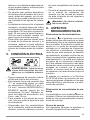
Energy saving
You can save energy during everyday
cooking if you follow hints outlined be-
low.
• When you heat water, only use the
quantity you require.
• If it is possible, always put the lids on
the cookware.
• Place the pan on the hob before you
switch it on.
• Put smaller pans on the smaller cook-
ing areas.
• Put the pans directly in the centre of
the cooking area.
• Use residual heat to keep the food
warm or melt it.
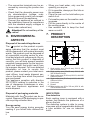
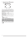
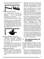
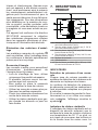
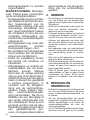
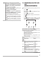
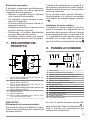
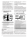
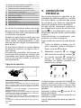
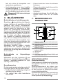
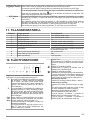
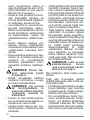
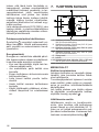
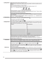
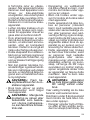
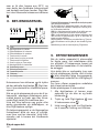
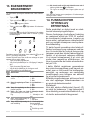
7. PRODUCT
DESCRIPTION
6
1Single cooking zone (210x190 mm) 2100 W, with
3000 W Booster function
2Single cooking zone (210x190 mm) 2100 W, with
3000 W Booster function
3Single cooking zone (R.200 mm) 2300 W, with 3000
W Booster function
4Single cooking zone (R.145 mm) 1400 W, with 1850
W Booster function
5Control panel
6Extractor
1 + 2 Bridge cooking area (220 x 395 mm) 3000 W, with
3700 W Booster function.
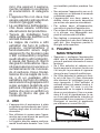
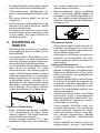
INDICATORS
Pan detection
Each cooking zone is equipped with a
system that detects the presence of a
pan on the hob.
The detection system is able to recog-
nise pans with a magnetisable bottom of
a type suitable for use on induction
hobs.
8

If the pan is removed during operation
or an unsuitable pan is used, the symbol
appears on the display.
Residual heat indicator
The residual heat indicator is a safety
feature, indicating that the surface of the
cooking area is still at a temperature of
50°C or above, which may cause burns
if touched with bare hands. The digit for
the corresponding cooking area indic-
ates .
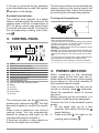
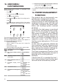
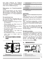
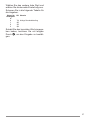
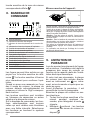
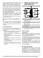
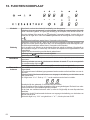
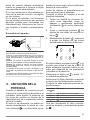
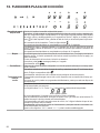
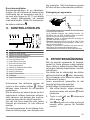
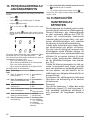
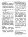
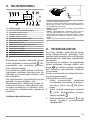
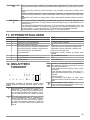
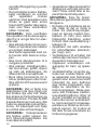
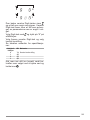
8. CONTROL PANEL
1On/Off
2Grease filter saturation indicator
3Cooking zone power level indicator
4Extractor power level indicator
5Extractor timer control
6Extractor controls zone symbol
7Cooking zone timer control
8Timer management zone
9Activated carbon filter saturation indicator
10 Melting
11 Lock key
12 Pause key
13 Scroll keypad
AAuto key
The cooking zones can be activated by
pressing the reference digit . The digit
becomes brighter to confirm the opera-
tion.
When a pan is placed on one of the 4
cooking areas, the hob automatically
detects its presence and lights up the
corresponding digit to activate it.
If there are no pans or other objects on
the hob, the digits are not visible.
The functions which can be selected are
always visible on the control panel, but
with a dimmed light. Select the functions
by touching the corresponding symbol.
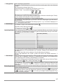
Turning on the appliance:
Press and hold the On/Off button for 2 seconds to turn the
hob on and activate its functions.
At this point the hob is on but all the cooking zones and the
hood are at zero power. The Hob will switch off automatic-
ally after 20 seconds if it is not being used.
Warning: For safety reasons the hob can always be turned
off using the On/Off button.
Warning: The functions that can be selected will always be
the ones that are illuminated/visible on the control panel,
and these will always be the only ones that can be activ-
ated.
The controls for the cooking areas, suction hood and timer
can be activated by pressing on the reference Digit.
The Digit lights up more intensely to confirm the operation.
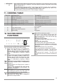
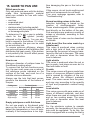
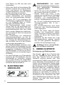
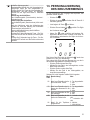
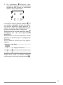
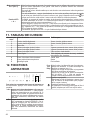
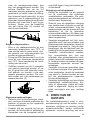
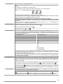
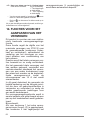
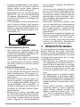
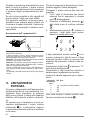
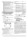
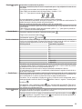
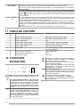
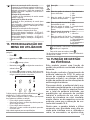
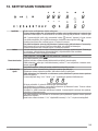
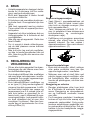
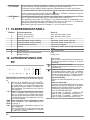
9. POWER LIMITATION
When connecting to the household
power supply for the first time, the in-
staller must set the power of the cooking
zones based on the actual capacity of
the household power supply.
If this is not necessary, the hob can be
turned on directly using , otherwise,
follow the operations below to access
the menu.
Before carrying out the procedure, it is
advisable to read the entire paragraph.
Connect the hob to the domestic mains
power.
1. All the digits light up for a few
seconds, then switch off and only
keeps flashing.
2. Press and hold : the digits in the
cooking area indicate .
9

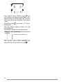
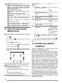
3. While holding down , start press-
ing the zone digits, proceeding anti-
clockwise.
1
2
4
3
The rear left digit indicates and a
number indicating the type of menu. The
front left digit indicates a number which
depends on the parameters indicated in
the selection.
Select the digit with and press “8” in
the power bar.
Select the front left digit and select the
correct setting.
See the following table for the specifica-
tions:
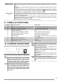
Value on the
power bar KW Notes
0 7.4 Standard initial setting
1 4.5
2 3.5
3 2.8
Once the correct value has been
entered, confirm by touching and hold-
ing .
10

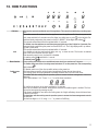
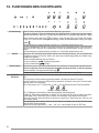
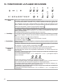
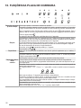
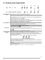
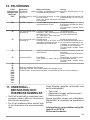
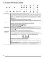
10. HOB FUNCTIONS
Child lock This function prevents accidental use of the appliance. This cannot be used during a cooking oper-
ation
To enable: remove all cookware from the appliance, turn the appliance off. f there is no pan on the
hob, press and hold for 3 seconds one of the digits (not visible) next to point on the left side. Re-
lease and slowly swipe along the power bar from 0 to BOOST. All the digits that indicate .
The operations described must be completed within 10 seconds.
To disable: turn the appliance on and then press and hold any of the 5 digits for 3 seconds. Re-
lease and slowly swipe along the power bar from BOOST to 0. The 5 digit displays will lit up indicat-
ing and 0 power level.
The operations described must be completed within 10 seconds.
Lock It is possible to lock the hob functions during use, e.g. to clean the hob. The function is enabled
even if the hob is switched off and on again.
If the electricity supply is cut, the function is disabled.
To enable: press and hold for 1 second.
To disable: press .
Boost function Every cooking area can be set to an additional power level for a maximum of 5 minutes.
To enable: select one of the 4 cooking areas and select “P” on the power bar. The corresponding
digit indicates .
To disable: select one of the other possible values on the power bar.
Cooking zone
timer The timer allows a specific cooking area to be switched off when the set time expires.
The cooking areas can be programmed individually because each one has its own timer.
To enable: With the cooking area in operation, press to access the timer management controls for
that zone.
The 3 digits indicate “0 0 0”. Press “+” or “-” to set the timer countdown.
Hours - Tenths - Minutes
To confirm the set time, do not touch anything for 10 seconds.
When the countdown has finished, the digits are reset and an audible signal is emitted. The func-
tion can be interrupted by pressing any key.
If the timer is enabled for more than one cooking area, the 3 digits will always show whichever timer
is about to finish first.
To deactivate: with the cooking area in operation, press to access the timer management controls
for that zone.
Set the three digits to “0 0 0” using “+” or “-” or press the On/Off key.
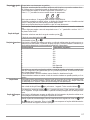
11

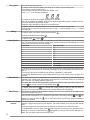
Timer (generic) Timer with alarm for generic use.
To enable: switch on the hob making sure there are no pans or active cooking areas.
The 3 digits to control the timer show “- - -”.
Press the digit to access the timer menu and display “0 0 0”.
Press “+” or “-” to set the timer countdown.
Hours - Tenths - Minutes
To confirm the set time, do not touch anything for 10 seconds.
When the countdown has finished, the digits are reset and an audible signal is emitted. The func-
tion can be interrupted by pressing any key.
Repeat the steps described to change the countdown value.
To disable: switch on the hob making sure there are no pans or active cooking areas.
Press the digit to access the timer menu and use “+” and “-” to set the display to “0 0 0” “-” or press
the On/Off key.
Melting To enable: select one of the 4 cooking zones and press .
The digit of the selected zone shows .
To disable: press or press .
Heating function This function is used to heat a pan to the maximum power before continuing to cook at a selected
level. The time interval for which the cooking zone is held at maximum power depends on the final
cooking level that has been set. See the table:
Power level Timer (seconds)
1 48
2 144
3 230
4 312
5 408
6 120
7 168
8 216
9 Not available
P Not available
To enable, with a pan on the hob and the cooking zone selected, press and hold the selected value
(from 1 to 8) on the power bar for 3 seconds. The display of the corresponding cooking zone indic-
ates “A”.
The cooking level can be increased, but the function is disabled if it is decreased.
It can also be disabled by touching and holding down the key of the cooking zone in question for 3
seconds.
Pause function This function allows you to pause/restart any active function on the hob, by reducing the power
available in the cooking zone and resetting all the functions. If the Pause function is not disabled
with 10 minutes, the hob automatically switches off.
To enable: With a pan on the hob and the cooking zone selected, press and hold the Pause func-
tion key for at least 1 second. All the displays show .
To disable: press and hold for 1 second until it starts flashing. Press any other key within 10
seconds. The function is disabled and the hob continues with the previous settings.
Recall function This function is used to recall the function settings of the hob if it is switched off by mistake or the
electricity is unexpectedly cut off.
When the hob is switched off, if it is switched on again with 6 seconds by touching , the key
flashes for 6 seconds. Press the key to recall the functions set previously. A beep is emitted to
confirm the operation.
Combo mode (“bridge”
function) This function allows 2 cooking areas to be combined to use and control them as if they were one
and have a bigger cooking area at your disposal. This function allows you to use pans with a wider
base.
Only the cooking areas on the left and on the right can be selected for use with this function.
To enable/disable: press the digits of the left-hand or right-hand cooking zones at the same time to
select the 2 areas be combined until the digit appears to show that the function has been en-
abled. The other digit is used to set the power level.
12

AUTO function
“A” The standard setting when the hob/suction hood is switched on is for the hood to start up in auto-
matic mode with the LED “A” brightly lit. The Hood comes into operation if the power in the cooking
areas is greater than “1”.
It is deactivated by pressing the LED “A” which changes intensity from bright to dim in confirmation.
It can also be deactivated by pressing a value, higher than “1”, on the power bar, which is con-
firmed by the fact that the LED “A” changes intensity from bright to dim.
It is reactivated by pressing the LED “A” which changes to brightly lit.
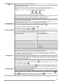
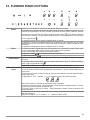
11. COOKING TABLE
Power level Cooking method To be used for
1Melting, heating gently Butter, chocolate, gelatine, sauces
2Melting, heating gently Butter, chocolate, gelatine, sauces
3Warming up Rice
4Prolonged cooking, thickening, stewing Vegetables, potatoes, sauces, fruit, fish
5Prolonged cooking, thickening, stewing Vegetables, potatoes, sauces, fruit, fish
6Prolonged cooking, braising Pasta, soups, braised meat
7Light frying Rösti (potato fry-ups), omelettes, breaded and fried
foods, sausages
8Frying, deep fat frying Meat, chips
9Quick frying at high temperature Steak
PQuick heating Boiling water
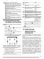
12. SUCTION HOOD
FUNCTIONS
The controls for the cooking areas, suction hood and timer
can be activated by pressing on the reference Digit.
“ 9 ” Press “9” on the power bar to set INTENSIVE 1
speed. This setting is timed to operate for 10
minutes. Once this time has passed, the system
will automatically return to the speed set previ-
ously. It is deactivated by selecting a different
speed.
“ P ” Press “9” on the power bar twice to set INTENSIVE
2 speed. This setting is timed to operate for 5
minutes. Once this time has passed, the system
will automatically return to the speed set previ-
ously. It is deactivated by selecting a different
speed.
Func-
tion
Delay
This function is only available if Automatic mode is
deactivated. Automatic mode is deactivated by
pressing “A”.
Press the suction hood Digit and set a speed on
the power bar.
Press the Timer management Digit, which was dis-
playing “CL” but will change to the countdown. This
is pre-set to 15 minutes.
Timer symbol
After selecting the suction hood Digit, press the
Timer Management Digit to set the countdown.
Grease filter maintenance symbol
The grease filter cleaning signal is displayed by
LED and it is always enabled.
Charcoal filter maintenance symbol
The hood is set by default to ducting mode. With
no loads on, press the Hood controls digit to en-
able the suction hood. Press and hold the Digit
again for 5 seconds to:
Activate the charcoal filter:
The charcoal (odour) filter symbol lights up for 1
second.
Deactivate the charcoal filter:
The charcoal (odour) filter symbol flashes twice.
After activation, the icon will light up to indicate that
maintenance must be carried out on the charcoal
(odour) filter.
Reset and reactivation of the charcoal filter
After having carried out maintenance on the filter:
press and hold for 5 seconds. - The LED of the
grease filter will turn off and the countdown will re-
start.
press and hold for 5 seconds. - The LED of the
anti-odour filter will turn off and the countdown will
restart.
13

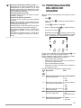
13. USER MENU
CUSTOMISATION
Before carrying out the procedure, it is advisable to read
the entire paragraph.
– Press .
– Press again and hold for 3 seconds.
– The key starts flashing.
– Press and hold : the digits in the cooking area in-
dicate .
– Hold and start pressing the digit of the cooking
areas in clockwise order starting from the left front
one.
4
3
1
2
The rear left digit alternately indicates and a number
from 2 to 7 indicating the menu code.
The front left digit indicates a number which depends on
the parameters indicated in the selection.
– Press the left rear digit.
– Select a number on the power bar to access the
menu code.
– Press the left front digit.
– Select a number on the power bar to select a value.
See the following table for the specifications:
Menu
code Description Value
U2 Key sound volume control
menu. 0 - Sound disabled
1 - Min.
3 - Max.
U3 Countdown beeper volume
control menu. 0 - Sound disabled
1 - Min.
3 - Max.
U4 Display brightness level con-
trol menu. 0 - Max.
9 - Min.
U5 Countdown display control
menu. 0 - Countdown dis-
play disabled
1 - Countdown dis-
play enabled
U6 Pan detection menu. 0 - Enabled
1 - Disabled
U7 Countdown end management
menu. 0 - Continuous flash-
ing and shut-down
1 - Ten flashes and
shut-down
2 - One flash and
shut-down
– Once the correct value has been entered, confirm by
touching and holding for 2 seconds.
– To exit the menu without saving, press .
If no operation is carried out the user menu will close after
1 minute.
14. POWER MANAGEMENT
FUNCTION
This product has an electronically con-
trolled power management function.
This function controls the delivery of the
maximum power of 3700 W between the
combined cooking areas (left side and
right side), optimising the power distri-
bution and avoiding system overload
situations.
To do this, the total power is monitored
continuously, and reduced when neces-
sary. If it is not possible to supply the
total power required, a control element
reduces by a predefined amount the
power in another cooking element so
that it is at a level immediately below its
respective power curve.This ensures
that the current absorption of 16 A is not
exceeded.
In this case the generator detects the
last command with the highest priority
sent by the user interface and, if neces-
sary, reduces the previous settings ac-
tivated for another cooking element.
The Power management function is first
activated when the presence of a pan is
detected on the cooking element.
Example:
If boost level (P) is selected for hob 1,
hob 2 cannot exceed level 9 at the same
time and will be automatically limited.”
14

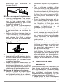
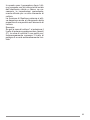
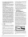
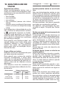
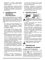
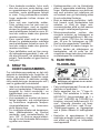
15. GUIDE TO PAN USE
Which pans to use
Only use pots and pans with the bottom
made from ferromagnetic material
which are suitable for use with induc-
tions hobs:
• cast iron
• enamelled steel
• carbon steel
• stainless steel (including partial)
• aluminium with ferromagnetic coating
or ferromagnetic plate
To determine if a pot or pan is suitable,
check for the symbol (usually
stamped on the bottom). You can also
hold a magnet to the bottom. If it clings
to the underside, the pan can be used
on an induction hob.
To ensure optimum efficiency, always
use pots and pans with a flat bottom that
distributes the heat evenly. If the bottom
is not perfectly flat, this will affect power
and heat conduction.
How to use
Minimum diameter of pot/pan base for
the different cooking areas.
To ensure that the hob functions prop-
erly, the pan must cover one or more of
the reference points indicated on the
surface of the hob, and must be of a
suitable minimum diameter.
Always use the hob that best corres-
ponds to the diameter of the bottom of
the pan.
Cooking areas Pan base diameter
Ø min.(recommen-
ded) Ø max (recommen-
ded)
Combined left 190 mm 230 mm
Single left 110 mm 190 mm
Single front right 110 mm 145 mm
Single rear right 110 mm 200 mm
Empty pots/pans or with thin base
Do not use empty or thin-based pots/
pans on the hob as it will be unable to
detect the temperature or turn off auto-
matically if the temperature is too high,
thus damaging the pan or the hob sur-
face.
If this occurs, do not touch anything and
wait for all components to cool down.
If an error message appears, refer to
“Troubleshooting”.
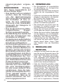
Normal working noises in the hob
Induction technology is based on the
creation of electromagnetic fields.
These electromagnetic fields generate
heat directly on the bottom of the pan.
Pots and pans may produce a variety of
noises or vibrations, according to their
construction.
These types of noise can be described
as follows:
Light buzz (like the noise made by a
transformer)
This noise is produced when cooking
with a high level of heat, and it is de-
termined by the amount of energy trans-
ferred by the hob to the pans. The noise
will stop or decrease when the heat
level is reduced.
Light whistle
This noise is produced when the pot or
pan is empty, and stops as soon as it is
filled with water or food.
Crackle
This noise occurs with pans made from
layers of numerous different materials,
and is caused by vibration of the sur-
faces where the different materials
meet. The noise comes from the pans,
and may vary according to the quantity
of food and preparation method being
used.
Loud whistle
This noise occurs with pans made up of
layers of different materials, and also
when these are used at maximum level
and on two cooking areas. The noise
will stop or decrease when the heat
level is reduced.
Fan noises
For the electronic system to operate
correctly, the temperature of the cooker
hob must be regulated. To do this, the
hob is equipped with a cooling fan that is
15

activated to reduce and regulate the
temperature in the electronic system.
The fan may continue to operate after
the appliance has been turned off, if the
temperature of the cooker hob is still de-
tected to be too high.
Rhythmic sounds like a clock ticking
This noise only occurs when at least
three cooking areas are operating, and
it disappears or decreases when some
of them are turned off.
The noises described are a normal fea-
ture of induction technology and are not
to be considered as defects.
16

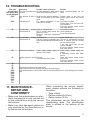
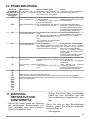
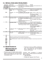
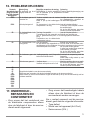
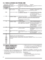
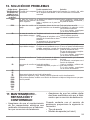
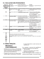
16. TROUBLESHOOTING
Error code Description Possible causes of the error Solution
“Acoustic signal
upon ignition. No er-
ror code displayed”
The hood command does
not work LIN cable damaged or badly connec-
ted to the hood electronic board check connection/replace the LIN
cable
ER03 Hob switches off after 10
sec. Continuous key activation detected.
Water or pan placed on the control
panel.
Remove water or pan from the
ceramic glass surface and control
panel.
ER21 Hob switches off. The internal temperature of elec-
tronic parts is too high. Let the hob cool down.
Please check if the hob has suffi-
cient ventilation.
If the error persists, please contact
After Sales Service.
E2 Corresponding cooking
area switches off. Empty or unsuitable pan.
Pan or ceramic glass surface tem-
perature too high.
Electronic component temperature
too high.
Let the hob cool down.
Use a suitable pan.
Do not heat empty pans.
E3 Corresponding cooking
area switches off. Unsuitable pan.
The pan is losing its magnetic prop-
erties and may damage the induction
hob.
Use a suitable pan.
The error is automatically cancelled
after 8 seconds and the cooking
area can be used again.
If any other errors occur, the pan
must be changed.
If the error persists, please contact
After Sales Service.
E6 Hob does not switch on. Power supply voltage and/or fre-
quency is out of range. Check mains voltage and/or fre-
quency.
If necessary, contact After Sales
Service.
E8 Cooking areas are turned
off. Fan fault.
Fan blocked by dust or fibres. Clean and remove foreign bodies
from the fan.
If the error persists, please contact
After Sales Service.
E4
E5
E7
E9
ER20
ER22
ER31
ER36
ER42
ER47
EA
EH
Disconnect the hob from the power supply.
Wait a few seconds, then reconnect the hob to the power supply.
If the problem persists, call the After Sales Service and specify the error code that appears on the dis-
play.
17. MAINTENANCE -
REPAIR AND
CONFORMITY
• Make sure that maintenance on elec-
trical components is only carried out
by the manufacturer or by the service
technicians.
• Make sure that damaged cables are
only replaced by the manufacturer or
by the service technicians.
When contacting the service depart-
ment, please provide the following in-
formation:
• Type of fault
• Device model (Art./Cod.)
• Serial number (S.N.)
This information can be found on the
identification plate. The identification
plate is affixed to the bottom of the
device.
17

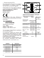
Information on the product pursuant
to EU regulation no. 66/2014
Reference standards:
EN/IEC 60350-2
EN/IEC 50564
This appliance has been designed,
manufactured and sold in compliance
with EEC Directives.
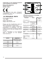
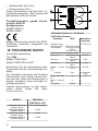
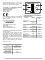
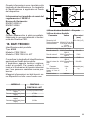
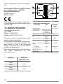
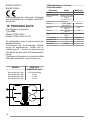
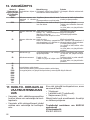
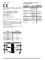
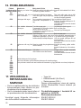
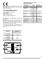
18. TECHNICAL DATA
Product identification
Type: 4300
Model: FSM 709 HI
Model: FSM 709 HI LL KIT
Please see the identification plate af-
fixed to the bottom of the product.
The manufacturer makes continual im-
provements to products. For this
reason, the text and illustrations in these
instructions for use may change without
warning.
Further information on the technical
data is available on the website:
www.franke.com
MODEL FSM 709 HI
FSM 709 HI LL KIT
Total maximum power (hob and
hood) 7.62 Kw (basic setting)
Total maximum power (hob and
hood) 4.72 Kw
Total maximum power (hob and
hood) 3.72 Kw
Total maximum power (hob and
hood) 3.02 Kw
1,2 Flexible cooking area 1 + 2 In bridge
3,4 Flexible cooking area
Parameter Value Dimensions
(mm)
Working dimensions - 700 × 520 (W x
D)
Power supply
voltage/frequency 220-240 V, 50 Hz; 220
V, 60 Hz 2N~ 380-415
V, 50 Hz;
2N~ 380 V, 60 Hz
Electrical and heating element data
Cooking area 1,2 2100 W; Power Boost:
3000 W 210 x 190
Cooking area 3 2300 W; Power Boost:
3000 W R 200
Cooking area 4 1400 W; Power Boost:
1850 W R 145
Flexible cooking
area
1+2
3000 W; Power Boost:
3700 W 210 x 390
Parameter Value Dimensions
(mm)
Weight of the device 21 kg
Number of cooking
areas 4
Heat source induction
18

DE
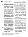
1. SICHERHEITSINFOR-
MATIONEN
Für die eigene Sicherheit
und die korrekte Funktion
des Geräts diese Be-
triebsanleitung bitte sorg-
fältig durchlesen, bevor es
installiert und in Betrieb
genommen wird. Die Be-
dienungsanleitung stets
zusammen mit dem Gerät
verwahren, auch wenn es
an Dritte weitergeben oder
übertragen wird. Es ist
wichtig, dass die Benutzer
mit allen Funktions- und
Sicherheitsmerkmalen
des Gerätes vertraut sind.
Die Induktionssysteme
dieser Kochfelder ent-
sprechen den Bestim-
mungen der EMV- und
EMF-Richtlinien und dür-
fen keine anderen elektro-
nischen Geräte stören.
Personen mit Herzschritt-
machern oder anderen
elektronischen Implanta-
ten sollten ihren Arzt oder
den Hersteller des implan-
tierten Geräts konsultie-
ren, um ihre Störanfällig-
keit zu beurteilen.
Elektrische Anschlüsse
sind von einem Fachmann
auszuführen. Bevor mit
dem elektrischen An-
schluss fortgefahren wird,
den Abschnitt ELEKTRI-
SCHER ANSCHLUSS le-
sen.
Bei Geräten mit Stromkabel
sind die Klemmen bzw. der
Drahtquerschnitt zwischen
dem Kabelverankerungspunkt
und den Klemmen so anzuord-
nen, dass der spannungsfüh-
rende Leiter vor dem Erdkabel
beim Austreten aus seiner Ver-
ankerung herausgezogen wer-
den kann.
• Der Hersteller haftet nicht für
etwaige Schäden, die durch
die fehlerhafte Installation
oder falschen Gebrauch ent-
stehen könnten.
• Sicherstellen, dass die Netz-
spannung der auf dem Ty-
penschild im Innern des Pro-
dukts angegebenen Span-
nung entspricht.
• Trennvorrichtungen müssen
in Übereinstimmung mit den
Verkabelungsvorschriften in
die fixe Anlage eingebaut
werden.
• Für Geräte der Klasse I muss
sichergestellt werden, dass
die häusliche Stromversor-
gung über eine angemesse-
ne Erdung verfügt.
• Verbinden Sie die Abzugs-
haube unter Verwendung ei-
ner passenden Rohrleitung
mit dem Rauchabzugskamin.
Beachten Sie das im Installa-
tionshandbuch angegebene,
käuflich erwerbbare Zubehör
(für Rundrohre: Mindest-
durchmesser 120 mm). Die
Länge der Ablassrohrleitung
sollte so kurz wie möglich
sein.
19

• Schließen Sie das Produkt
mit einem allpoligen Schalter
an das Stromnetz an.
• Die Vorschriften zum Auslas-
sen von Luft sind zu beach-
ten.
• Schließen Sie die Abzugs-
haube nicht an Auslassleitun-
gen an, die Verbrennungsga-
se (Kessel, Schornsteine
usw.) transportieren.
• Falls die Abzugshaube
gleichzeitig mit nichtelektri-
schen Geräten (z.B. Gasge-
räten) verwendet wird, muss
der Raum über eine ausrei-
chende Lüftung verfügen, da-
mit der Rückfluss der Abgase
verhindert wird. Falls das
Kochgerät zusammen mit
Geräten verwendet wird, die
mit nichtelektrischen Ener-
giequellen betrieben werden,
darf der Unterdruck im Raum
4 Pa nicht überschreiten, um
zu verhindern, dass Dämpfe
vom Kochgerät zurück in den
Raum gesaugt werden.
• Die Luft darf nicht in eine
Rohrleitung ausgestoßen
werden, die als Abzug für
gasbetriebene oder andere
Brennstoffe verwendet wird.
• Wenn das Netzkabel beschä-
digt ist, muss es durch den
Hersteller, ein autorisiertes
Servicezentrum oder einen
kompetenten Techniker er-
setzt werden, um jedes Risiko
oder jede Gefahrensituation
zu vermeiden.
• Den Stecker des Geräts in ei-
ne den einschlägigen Vor-
schriften entsprechende zu-
gängliche Steckdose ste-
cken.
• In Bezug auf die technischen
und sicherheitstechnischen
Maßnahmen zur Ableitung
der Dämpfe ist es wichtig, die
von den örtlichen Behörden
festgelegten Regeln genau
einzuhalten.
WARNHINWEIS: Bevor
das Gerät installiert wird,
die Schutzfolien abzie-
hen.
• Nur die mit dem Gerät gelie-
ferten Schrauben und sonsti-
gen Artikel verwenden.
WARNHINWEIS: Die
mangelnde Verwendung
von Schrauben und Be-
festigungselementen ge-
mäß der vorliegenden An-
leitung kann zu Strom-
schlaggefahr führen.
• Reinigungs- und Wartungs-
arbeiten dürfen nicht von Kin-
dern durchgeführt werden, es
sei denn unter Aufsicht eines
Erwachsenen.
• Kinder müssen beaufsichtigt
werden, damit sichergestellt
wird, dass sie nicht mit dem
Gerät spielen.
• Dieses Gerät darf nicht von
Personen (einschließlich Kin-
dern) mit eingeschränkten
körperlichen, sensorischen
oder geistigen Fähigkeiten
oder ohne Erfahrung und
Wissen verwendet werden,
es sei denn, sie werden auf-
merksam überwacht und hin-
sichtlich der sicheren Ver-
wendung des Geräts durch
20
La page est en cours de chargement...
La page est en cours de chargement...
La page est en cours de chargement...
La page est en cours de chargement...
La page est en cours de chargement...
La page est en cours de chargement...
La page est en cours de chargement...
La page est en cours de chargement...
La page est en cours de chargement...
La page est en cours de chargement...
La page est en cours de chargement...
La page est en cours de chargement...
La page est en cours de chargement...
La page est en cours de chargement...
La page est en cours de chargement...
La page est en cours de chargement...
La page est en cours de chargement...
La page est en cours de chargement...
La page est en cours de chargement...
La page est en cours de chargement...
La page est en cours de chargement...
La page est en cours de chargement...
La page est en cours de chargement...
La page est en cours de chargement...
La page est en cours de chargement...
La page est en cours de chargement...
La page est en cours de chargement...
La page est en cours de chargement...
La page est en cours de chargement...
La page est en cours de chargement...
La page est en cours de chargement...
La page est en cours de chargement...
La page est en cours de chargement...
La page est en cours de chargement...
La page est en cours de chargement...
La page est en cours de chargement...
La page est en cours de chargement...
La page est en cours de chargement...
La page est en cours de chargement...
La page est en cours de chargement...
La page est en cours de chargement...
La page est en cours de chargement...
La page est en cours de chargement...
La page est en cours de chargement...
La page est en cours de chargement...
La page est en cours de chargement...
La page est en cours de chargement...
La page est en cours de chargement...
La page est en cours de chargement...
La page est en cours de chargement...
La page est en cours de chargement...
La page est en cours de chargement...
La page est en cours de chargement...
La page est en cours de chargement...
La page est en cours de chargement...
La page est en cours de chargement...
La page est en cours de chargement...
La page est en cours de chargement...
La page est en cours de chargement...
La page est en cours de chargement...
La page est en cours de chargement...
La page est en cours de chargement...
La page est en cours de chargement...
La page est en cours de chargement...
La page est en cours de chargement...
La page est en cours de chargement...
La page est en cours de chargement...
La page est en cours de chargement...
La page est en cours de chargement...
La page est en cours de chargement...
La page est en cours de chargement...
La page est en cours de chargement...
La page est en cours de chargement...
La page est en cours de chargement...
La page est en cours de chargement...
La page est en cours de chargement...
La page est en cours de chargement...
La page est en cours de chargement...
La page est en cours de chargement...
La page est en cours de chargement...
La page est en cours de chargement...
La page est en cours de chargement...
La page est en cours de chargement...
La page est en cours de chargement...
La page est en cours de chargement...
La page est en cours de chargement...
La page est en cours de chargement...
La page est en cours de chargement...
La page est en cours de chargement...
La page est en cours de chargement...
La page est en cours de chargement...
La page est en cours de chargement...
La page est en cours de chargement...
La page est en cours de chargement...
La page est en cours de chargement...
La page est en cours de chargement...
La page est en cours de chargement...
La page est en cours de chargement...
La page est en cours de chargement...
La page est en cours de chargement...
La page est en cours de chargement...
La page est en cours de chargement...
La page est en cours de chargement...
La page est en cours de chargement...
La page est en cours de chargement...
La page est en cours de chargement...
La page est en cours de chargement...
La page est en cours de chargement...
La page est en cours de chargement...
La page est en cours de chargement...
La page est en cours de chargement...
La page est en cours de chargement...
La page est en cours de chargement...
La page est en cours de chargement...
La page est en cours de chargement...
La page est en cours de chargement...
La page est en cours de chargement...
La page est en cours de chargement...
La page est en cours de chargement...
La page est en cours de chargement...
La page est en cours de chargement...
La page est en cours de chargement...
La page est en cours de chargement...
La page est en cours de chargement...
La page est en cours de chargement...
La page est en cours de chargement...
La page est en cours de chargement...
La page est en cours de chargement...
La page est en cours de chargement...
La page est en cours de chargement...
La page est en cours de chargement...
La page est en cours de chargement...
La page est en cours de chargement...
La page est en cours de chargement...
La page est en cours de chargement...
La page est en cours de chargement...
La page est en cours de chargement...
La page est en cours de chargement...
La page est en cours de chargement...
La page est en cours de chargement...
La page est en cours de chargement...
La page est en cours de chargement...
La page est en cours de chargement...
La page est en cours de chargement...
La page est en cours de chargement...
La page est en cours de chargement...
La page est en cours de chargement...
La page est en cours de chargement...
La page est en cours de chargement...
La page est en cours de chargement...
La page est en cours de chargement...
La page est en cours de chargement...
La page est en cours de chargement...
La page est en cours de chargement...
La page est en cours de chargement...
La page est en cours de chargement...
-
 1
1
-
 2
2
-
 3
3
-
 4
4
-
 5
5
-
 6
6
-
 7
7
-
 8
8
-
 9
9
-
 10
10
-
 11
11
-
 12
12
-
 13
13
-
 14
14
-
 15
15
-
 16
16
-
 17
17
-
 18
18
-
 19
19
-
 20
20
-
 21
21
-
 22
22
-
 23
23
-
 24
24
-
 25
25
-
 26
26
-
 27
27
-
 28
28
-
 29
29
-
 30
30
-
 31
31
-
 32
32
-
 33
33
-
 34
34
-
 35
35
-
 36
36
-
 37
37
-
 38
38
-
 39
39
-
 40
40
-
 41
41
-
 42
42
-
 43
43
-
 44
44
-
 45
45
-
 46
46
-
 47
47
-
 48
48
-
 49
49
-
 50
50
-
 51
51
-
 52
52
-
 53
53
-
 54
54
-
 55
55
-
 56
56
-
 57
57
-
 58
58
-
 59
59
-
 60
60
-
 61
61
-
 62
62
-
 63
63
-
 64
64
-
 65
65
-
 66
66
-
 67
67
-
 68
68
-
 69
69
-
 70
70
-
 71
71
-
 72
72
-
 73
73
-
 74
74
-
 75
75
-
 76
76
-
 77
77
-
 78
78
-
 79
79
-
 80
80
-
 81
81
-
 82
82
-
 83
83
-
 84
84
-
 85
85
-
 86
86
-
 87
87
-
 88
88
-
 89
89
-
 90
90
-
 91
91
-
 92
92
-
 93
93
-
 94
94
-
 95
95
-
 96
96
-
 97
97
-
 98
98
-
 99
99
-
 100
100
-
 101
101
-
 102
102
-
 103
103
-
 104
104
-
 105
105
-
 106
106
-
 107
107
-
 108
108
-
 109
109
-
 110
110
-
 111
111
-
 112
112
-
 113
113
-
 114
114
-
 115
115
-
 116
116
-
 117
117
-
 118
118
-
 119
119
-
 120
120
-
 121
121
-
 122
122
-
 123
123
-
 124
124
-
 125
125
-
 126
126
-
 127
127
-
 128
128
-
 129
129
-
 130
130
-
 131
131
-
 132
132
-
 133
133
-
 134
134
-
 135
135
-
 136
136
-
 137
137
-
 138
138
-
 139
139
-
 140
140
-
 141
141
-
 142
142
-
 143
143
-
 144
144
-
 145
145
-
 146
146
-
 147
147
-
 148
148
-
 149
149
-
 150
150
-
 151
151
-
 152
152
-
 153
153
-
 154
154
-
 155
155
-
 156
156
-
 157
157
-
 158
158
-
 159
159
-
 160
160
-
 161
161
-
 162
162
-
 163
163
-
 164
164
-
 165
165
-
 166
166
-
 167
167
-
 168
168
-
 169
169
-
 170
170
-
 171
171
-
 172
172
-
 173
173
-
 174
174
-
 175
175
-
 176
176


Smart FSM 709 HI Manuel utilisateur
- Catégorie
- Plaques de cuisson
- Taper
- Manuel utilisateur
dans d''autres langues
- italiano: Smart FSM 709 HI Manuale utente
- English: Smart FSM 709 HI User manual
- español: Smart FSM 709 HI Manual de usuario
- Deutsch: Smart FSM 709 HI Benutzerhandbuch
- Nederlands: Smart FSM 709 HI Handleiding
- português: Smart FSM 709 HI Manual do usuário
- dansk: Smart FSM 709 HI Brugermanual
- eesti: Smart FSM 709 HI Kasutusjuhend
- svenska: Smart FSM 709 HI Användarmanual
Autres documents
-
Faber Galileo Smart BK A600 Manuel utilisateur
-
IKEA 804.678.10 Manuel utilisateur
-
IKEA Utnaemnd Induction Hob 500-Black Manuel utilisateur
-
-
-
ELICA NIKOLATESLA SWITCH Manuel utilisateur
-
-
Scholtes CI 96I K Mode d'emploi
-
Whirlpool CE6IFA (W) F Mode d'emploi