
IT-USB/KEY
Interfaccia USB/KEY
USB/KEY Interface
Fig. 1
Fig. 2
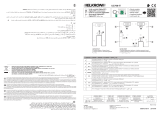
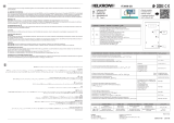
LED PC LED USB
Fig. 3
ELKRON
TEL. +39.011.3986711 – FAX +39.011.3986703
www.elkron.com – mail to: [email protected]
ELKRON è un marchio commerciale di URMET S.p.A.
ELKRON is a trademark of URMET S.p.A.
Via Bologna, 188/C - 10154 Torino (TO) – Italy
www.urmet.com
ITALIANO
ATTENZIONE: in questo documento sono
riportate solo alcune indicazioni essenziali sul
prodotto. per ulteriori e dettagliate informazioni fare
riferimento ai manuali delle centrali MP500.
DESCRIZIONE GENERALE
L’interfaccia IT-USB/KEY consente di collegare alla
Centrale MP500, un computer per la sua programmazione
e una Chiave USB (Pen Drive) per il salvataggio ed il
recupero della completa programmazione del sistema,
dello storico eventi, dei codici e delle chiavi.
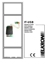
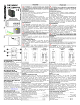
CONNESSIONE ALLA CENTRALE
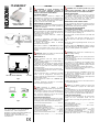
Inserire il cavo Flat in dotazione nel connettore polarizzato
in posizione A di fig.1 (dopo aver estratto i ponticelli con
la Centrale non alimentata).
UTILIZZO CHIAVE USB (FLASH MEMORY SU PEN DRIVE)
L’interfaccia USB/KEY è in grado di gestire Memorie Flash
USB di tipo FAT12, FAT16 e FAT32 (no NTFS) con
assorbimento massimo di 100mA @ 5V.
È stata testata su memorie Flash fino a 16GB con
partizione singola.
Le operazioni di “Salvataggio” e “Recupero” dei dati,
possono essere effettuate quando la Centrale è posta
nello stato di “Manutenzione”.
Per eseguire tali operazioni riferirsi al “Manuale
Programmazione” del sistema.
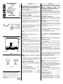
Durante questa condizione, il LED USB (fig.3) indica
l’avvenuto riconoscimento della Chiave USB con un
lampeggio. Poi rimane acceso fisso fino alla fine delle
operazioni.
Attenzione: Durante la scrittura o la lettura dei dati
la Chiave USB non deve essere rimossa!
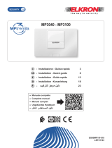
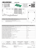
CONNESSIONE AL PC
Connettere l’interfaccia USB alla centrale prima di
collegarla al PC.
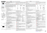
Inserire il cavo USB in dotazione nel connettore B (fig.2) e
in una porta USB libera del PC.
Se l’interfaccia viene riconosciuta dal sistema operativo
(Windows 2000, XP, Vista, Windows 7, Windows 8) il PC
aggiungerà una porta COM con numerazione seguente
alle porte già esistenti.
In caso contrario verrà richiesto di caricare i Driver FDTI.
Questi sono disponibili sul CD di “Hi-Connect” o scaricabili
dal sito internet di Elkron.
Quando la connessione al PC si è instaurata, è possibile
utilizzare il SW di configurazione “HI-Connect” per
eseguire le operazioni di programmazione e di ricezione
degli allarmi dalla Centrale.
Durante il colloquio tra Centrale e PC il LED PC (fig.3)
rimane acceso.
Per ulteriori informazioni sull’utilizzo di “HI-Connect”
riferirsi al “Manuale Programmazione”.
Nota: L’interfaccia IT USB/KEY si utilizza
tipicamente durante la manutenzione per programmare i
parametri di centrale.
Se alla centrale è connesso anche il “Videogateway 4T”,
prima di eseguire qualunque operazione con l’interfaccia
USB è necessario scollegare il cavo Flat 10 vie dall’IT
RS232 connessa al “Videogateway 4T”.
CARATTERISTICHE TECNICHE
L’interfaccia viene alimentata direttamente dalla centrale,
pertanto è necessario considerare anche il consumo Max
nel conteggio generale dell’assorbimento dell’impianto.
Tensione nominale di alimentazione:...................13,8 Vcc
(da centrale su cavo flat)
Tensione di funzionamento min/max: ..........9Vcc ÷ 15Vcc
Corrente nominale assorbita a 12 Vcc:
Standby (Key USB e PC non connessi) ............... 5 mA
Con Key USB in lettura/scrittura..................65 mA Max
PC connesso in colloquio................................... 15 mA
Corrente massima fornita alla Chiave USB........... 100 mA
Dimensioni (L x H x P), in mm...................... 92 x 110 x 30
ENGLISH
WARNING: This document provides only some
essential product information. Refer to the MP500
control panel manuals for more detailed information.
GENERAL DESCRIPTION
The IT-USB/KEY interface is used to connect a computer
to the MP500 control panel in order to program the
computer and a USB flash drive or memory key (Pen
Drive) to save and retrieve the whole system
programming, the history of events, codes and keys.
CONNECTIONS TO THE CONTROL PANEL
Insert the supplied Flat cable into the polarised connector
in position A as shown in Fig. 1 (after removing the
jumpers and with control panel not powered).
HOW TO USE THE USB FLASH DRIVE
(FLASH MEMORY IN PEN DRIVE)
The USB/KEY Interface is capable of managing FAT12,
FAT16 and FAT32 (not NTFS) USB Flash Memories and
has a maximum input of 100mA @ 5V.
It has been tested on Flash memories up to 16GB with
single partition.
The data “Saving" and "Recovery” operations can be
carried out when the control panel is in “Maintenance”
mode.
Refer to the system “Programming Manual” to carry out
these operations.
Given this condition, the USB LED (fig.3) flashes to signal
that the USB Memory Key has been recognised. The light
remains on until the operations are completed.
Warning: Never remove the USB Memory Key
during data writing o reading!
PC CONNECTION
Connect the USB Interface to the control panel before
connecting it to the PC.
Insert the supplied USB cable into connector B (fig.2) and
into a PC free USB port.
If the interface is recognised by the operating system
(Windows 2000, XP, Vista, Windows 7, Windows 8), the
PC will add a COM port which will be assigned a number
after the already existing port.
Otherwise, it will be necessary to load the FDTI Drivers.
These drivers are available on the “HI-Connect” CD or can
be downloaded from the Elkron website.
Once the connection to the PC is established, you can use
the "HI-Connect” configuration SW to execute the
programming and reception operations related to the
alarms from the Control panel.
During the communication between the Control panel and
the PC, the PC LED (fig.3) remains on.
For further information on how to use “HI-Connect” refer to
the “Programming Manual”.
Note: The IT USB/KEY interface is usually used
during the maintenance to program the control panel
parameters.
If the "Videogateway 4T" is also connected to the control
panel; it is necessary to disconnect the Flat cable 10ways
from the IT RS232 connected to the “Videogateway 4T”
before carrying out any operation with the USB interface.
TECHNICAL SPECIFICATIONS
The interface is directly powered by the control panel;
therefore, the max. consumption should also be
considered when measuring the general input of the
system.
Rated supply voltage:.......................................... 13.8 Vcc
(from control panel via flat cable)
Min/max operating voltage: ..........................9Vcc ÷ 15Vcc
Rated input current at 12 Vcc:
Standby (USB Key and PC not connected)...........5 mA
With USB Key in reading/writing mode.......65 mA Max
PC connected for communication.......................15 mA
Maximum current supplied to the USB Memory Key.. 100 mA
Dimensions (W x H x D), in mm ...................92 x 110 x 30
DS80MP5K-001D LBT80129
KEY USB (FLASH MEMORY
)
PC cabl
e
A B
A

IT-USB/KEY
Interface USB/KEY
Schnittstelle USB/KEY
Fig. 1
Fig/Abb. 2
LED PC LED USB
Fig/Abb. 3
ELKRON
TEL. +39.011.3986711 – FAX +39.011.3986703
www.elkron.com – mail to: [email protected]
ELKRON est une marque commercial d’
URMET S.p.A.
ELKRON ist ein eingetragenes Warenzeichen von
URMET S.p.A.
Via Bologna, 188/C - 10154 Torino (TO) – Italy
www.urmet.com
FRANÇAIS
ATTENTION: dans ce document ne sont
reportées que quelques indications essentielles sur le
produit. pour obtenir d’autres informations détaillées,
consulter les manuels des centrales MP500.
DESCRIPTION GÉNÉRALE
L’interface IT-USB/KEY permet de connecter la centrale
MP500 à un ordinateur pour sa programmation ou à une
clé USB (mémoire Flash) pour la sauvegarde ou la
restauration de la configuration du système, historiques
des événements, des codes et des clés.
CONNEXION A LA CENTRALE
Insérez avec l’aide du détrompeur le connecteur polarisé
du câble plat fourni dans le sens de la figure 1 (après la
suppression des pontets avec la Centrale non alimentée).
UTILISATION DE LA CLE USB
L’interface USB/KEY permet de gérer des mémoires de
clés USB du type FAT12, FAT16 et FAT32 (non NTFS)
avec une absorption maximum de 100mA @ 5V.
Il a été testé une mémoire Flash jusqu'à 16 GB avec une
seule partition.
Les opérations de “Sauvegarde” et de “Restauration” pour
les données peuvent être faites lorsque la centrale est
positionnée dans l'état de « Maintenance ».
Pour effectuer ces tâches se référencer au « Manuel de
programmation » du système.
Durant cette utilisation, la LED de l’icône USB (fig. 3)
indique la reconnaissance de la clé USB avec un
clignotement. Puis reste allumée jusqu'à la fin des
opérations.
Attention: Durant l’écriture ou la lecture de
données la clé USB ne doit pas être déconnectée!
CONNEXION AU PC
Connecter l'interface USB à la Centrale avant la
connexion PC.
Insérez le câble USB dans le connecteur B (fig. 2) et dans
un port USB libre de votre PC.
Si l'interface est reconnu par le système d'exploitation
(Windows 2000, XP, Vista, Windows 7, Windows 8) le PC
ajoutera un port COM numéroté suivant l’ordre des ports
existants.
Sinon vous serez invité à charger les pilotes FDTI. Ils sont
disponibles sur le CD de “Hi-Connect” ou téléchargeable
depuis le site Web d’Elkron.
Lorsque la connexion au PC a été établie, vous pouvez
utiliser le logiciel de configuration “HI-Connect” pour
effectuer la programmation et recevoir des alertes de la
Centrale.
Au cours de la communication entre la centrale et le PC la
LED sous l’icône PC sur le boîtier (fig. 3) reste allumée.
Pour plus d'informations sur l'utilisation de « HI-Connect »
référencez-vous dans le « Manuel de programmation ».
Note: L’interface IT USB/KEY est généralement
utilisé lors de l'entretien pour programmer les paramètres
de la centrale.
Si la Centrale est connectée à la « Videogateway 4 T »,
avant d'effectuer toute opération avec l'interface USB, il
est nécessaire de débrancher le câble plat 10-plots
RS232 connecté à la « Videogateway 4 T ».
CARACTERISTIQUES TECHNIQUES
L'interface est alimentée directement à partir de la
centrale, donc vous devez également considérer la
consommation de courant maximum absorbée par la
configuration totale.
Tension nominale d’alimentation:.........................13,8 Vcc
(par la centrale sur le câble plat)
Tension de Fonctionnement min/max:.........9Vcc ÷ 15Vcc
Note : la consommation de courant à 12 Vcc:
Au repos (Key USB et PC non connectés)........... 5 mA
Avec clé USB en lecture/écriture.................65 mA Max
PC connecté en communication......................... 15 mA
Courant maximal fourni à la clé USB.................... 100 mA
Dimensions (L x H x P), in mm..................... 92 x 110 x 30
DEUTSCH
ACHTUNG: IN DIESER UNTERLAGE SIND NUR
EINIGE HAUPTSÄCHLICHE ANGABEN ÜBER DAS
PRODUKT ENTHALTEN, MEHR UND
DETAILLIERTERE INFORMATIONEN FINDEN SIE IN
DEN HANDBÜCHERN DER MP500-ZENTRALEN.
ALLGEMEINE BESCHREIBUNG
Die Schnittstelle IT-USB/KEY ermöglicht den Anschluss
eines Computers für die Programmierung und eines USB-
Schlüssels (Pen Drive) für die Speicherung und das
Backup der kompletten Programmierung des Systems,
der historischen Vorgänge, der Kode und der Schlüssel an
die MP500-Zentrale.
VERBINDUNG MIT DER ZENTRALE
Das mitgelieferte Flachkabel an den polarisierten
Steckverbinder in Position A der Abb.1 (nach Auszug der
Überbrückung bei nicht eingespeister Zentrale)
anschliessen.
BENUTZUNG DES USB-SCHLÜSSELS (FLASH MEMORY
AUF PEN DRIVE)
Die Schnittstelle USB/KEY ist in der Lage, USB Flash-
Schlüssel des Typs FAT12, FAT16 und FAT32 (nicht
NTFS) mit einer maximalen Stromabnahme von 100mA
@ 5V zu verwalten.
Sie wurden auf Flash-Speichern bis zu 16GB mit
Einzelteilung getestet.
Die Vorgänge für “Speicherung” und “Backup” der Daten
können ausgeführt werden, wenn sich die Zentrale im
„Wartungsmodus“ befindet.
Für die Ausführung dieser Vorgänge siehe das
“Programmierungshandbuch” des Systems.
Während diesem Modus zeigt das USB LED (Abb.3) die
erfolgte Erkenntnis des USB-Schlüssels durch Blinken an.
Danach bleibt es bis Beendigung der Arbeiten
eingeschaltet.
Achtung: Während dem Schreiben oder Lesen der
Daten darf der USB-Schlüssel nicht abgezogen werden!
VERBINDUNG MIT DEM PC
Die USB Schnittstelle zuerst mit der Zentrale und dann mit
dem Compter verbinden
Das mitgelieferte USB-Kabel in den Steckverbinder B
(Abb.2) und in ein freies USB-Port des Computers
einstecken.
Wenn die Schnittstelle von dem Anwendersystem
(Windows 2000, XP, Vista, Windows 7, Windows 8)
erkannt wird, fügt der Computer ein COM-Port mit der
nächsten freien Nummer hinzu.
Anderenfalls wird der Download der FDTI Treiber verlangt.
Diese Treiber befinden sich auf der CD “Hi-Connect” oder
können aus der Internetsite Elkron herunter geladen
werden.
Nachdem sich die Verbindung zum Computer aufbaute,
kann die Konfigurationssoftware “HI-Connect” für die
Ausführung der Programmierung und Empfang der
Alarme von der Zentrale benutzt werden.
Während der Kommunikation zwischen Zentrale und PC
bleibt die PC LED (Abb.3) eingeschaltet.
Mehr Informationen über die Verwendung von “HI-
Connect” finden Sie im “Programmierhandbuch”.
Hinweis: Die IT USB/KEY Schnittstelle wird
normalerweise während der Wartung für die
Programmierung der Parameter der Zentrale benutzt.
Wenn die Zentrale auch mit “Videogateway 4T” verbunden
ist, muss vor jeglicher Arbeit mit der USB Schnittstelle das
10-wegige Flachkabel von der mit “Videogateway 4T“
verbundenen IT RS232 abgetrennt werden.
TECHNISCHE MERKMALE
Die Schnittstelle wird direkt von der Zentrale eingespeist
und daher muss auch ihr Höchstverbrauch bei der
allgemeinen Berechnung der Stromabnahme der Anlage
berücksichtigt werden.
Nennspannung der Versorgung: ......................... 13,8 Vcc
(von der Zentrale auf Flachkabel)
Betriebsspannung min/max:.........................9Vcc ÷ 15Vcc
bei 12 Vcc absorbierter Nennstrom:
Standby (Key USB und PC nicht angeschlossen).5 mA
mit USB Key bei Lesen/Schreiben: ............ 65 mA Max
PC in Kommunikation angeschlossen.................15 mA
Max. an den USB-Schlüssel abgegebener Strom..100 mA
Abmessengen (L x H x T), in mm.................92 x 110 x 30
DS80MP5K-001D LBT80129
CL
É
US
B
PC cabl
e
A B
A
-
 1
1
-
 2
2


dans d''autres langues
- italiano: Elkron IT USB/KEY Guida d'installazione
- English: Elkron IT USB/KEY Installation guide
- Deutsch: Elkron IT USB/KEY Installationsanleitung
Documents connexes
-
 Elkron KP500DP/N Guide d'installation
-
 Elkron ER600 Guide d'installation
-
 Elkron SV504 Guide d'installation
-
 Elkron IT USB Guide d'installation
-
 Elkron MP3100 Guide de démarrage rapide
-
 Elkron UC700-IT Guide d'installation
-
 Elkron DK510M-P/B Guide d'installation
-
 Elkron ER700-ZB Guide d'installation
-
 Elkron IT3000-2G Manuel utilisateur
-
Elkron IT3000-4G Manuel utilisateur


