
SPRINT 06
SPRINT 06
ISTRUZIONI PER L’USO - INSTRUCTIONS FOR USE
ISTRUZIONI PER L’USO - INSTRUCTIONS FOR USE
INSTRUCTIONS POUR L’USAGER - INSTRUCCIONES PARA EL USO
INSTRUCTIONS POUR L’USAGER - INSTRUCCIONES PARA EL USO
GEBRAUCHSANLEITUNG - GIDS VOOR DE GEBRUIKER
GEBRAUCHSANLEITUNG - GIDS VOOR DE GEBRUIKER

ITALIANO
AVVERTENZE PER L’INSTALLATORE
OBBLIGHI GENERALI PER LA SICUREZZA
ATTENZIONE! È importante per la sicurezza delle persone seguire attentamente
tutta l’istruzione. Una errata installazione o un errato uso del prodotto può
portare a gravi danni alle persone.
Leggere attentamente le istruzioni prima di iniziare l’installazione del prodotto.
I materiali dell’imballaggio (plastica, polistirolo, ecc.) non devono essere lasciati alla
portata dei bambini in quanto potenziali fonti di pericolo.
Conservare le istruzioni per riferimenti futuri.
Questo prodotto è stato progettato e costruito esclusivamente per l’utilizzo indicato in
questa documentazione. Qualsiasi altro utilizzo non espressamente indicato potrebbe
pregiudicare l’integrità del prodotto e/o rappresentare fonte di pericolo.
GENIUS declina qualsiasi responsabilità derivata dall’uso improprio o diverso da
quello per cui l’automatismo è destinato.
Non installare l’apparecchio in atmosfera esplosiva: la presenza di gas o fumi
infiammabili costituisce un grave pericolo per la sicurezza.
Gli elementi costruttivi meccanici devono essere in accordo con quanto stabilito
dalle Norme EN 12604 e EN 12605.
Per i Paesi extra-CEE, oltre ai riferimenti normativi nazionali, per ottenere un livello di
sicurezza adeguato, devono essere seguite le Norme sopra riportate.
GENIUS non è responsabile dell’inosservanza della Buona Tecnica nella costru-
zione delle chiusure da motorizzare, nonché delle deformazioni che dovessero
intervenire nell’utilizzo.
L’installazione deve essere effettuata nell’osservanza delle Norme EN 12453 e EN
12445. Il livello di sicurezza dell’automazione deve essere C+D.
Prima di effettuare qualsiasi intervento sull’impianto, togliere l’alimentazione elettrica
e scollegare le batterie.
Prevedere sulla rete di alimentazione dell’automazione un interruttore onnipolare
con distanza d’apertura dei contatti uguale o superiore a 3 mm. È consigliabile l’uso
di un magnetotermico da 6A con interruzione onnipolare.
Verificare che a monte dell’impianto vi sia un interruttore differenziale con soglia
da 0,03 A.
Verificare che l’impianto di terra sia realizzato a regola d’arte e collegarvi le parti
metalliche della chiusura.
L’automazione dispone di una sicurezza intrinseca antischiacciamento costituita
da un controllo di coppia. E’ comunque necessario verificarne la sogli di intervento
secondo quanto previsto dalle Norme indicate al punto 10.
I dispositivi di sicurezza (norma EN 12978) permettono di proteggere eventuali
aree di pericolo da Rischi meccanici di movimento, come ad Es. schiacciamento,
convogliamento, cesoiamento.
Per ogni impianto è consigliato l’utilizzo di almeno una segnalazione luminosa nonché
di un cartello di segnalazione fissato adeguatamente sulla struttura dell’infisso, oltre
ai dispositivi citati al punto “16”.
GENIUS declina ogni responsabilità ai fini della sicurezza e del buon funzionamento
dell’automazione, in caso vengano utilizzati componenti dell’impianto non di
produzione GENIUS.
Per la manutenzione utilizzare esclusivamente parti originali GENIUS.
Non eseguire alcuna modifica sui componenti facenti parte del sistema d’au-
tomazione.
L’installatore deve fornire tutte le informazioni relative al funzionamento manuale
del sistema in caso di emergenza e consegnare all’Utente utilizzatore dell’impianto
il libretto d’avvertenze allegato al prodotto.
Non permettere ai bambini o persone di sostare nelle vicinanze del prodotto
durante il funzionamento.
L’applicazione non può essere utilizzata da bambini, da persone con ridotte ca-
pacità fisiche, mentali, sensoriali o da persone prive di esperienza o del necessario
addestramento.
Tenere fuori dalla portata dei bambini radiocomandi o qualsiasi altro datore di impul-
so, per evitare che l’automazione possa essere azionata involontariamente.
Il transito tra le ante deve avvenire solo a cancello completamente aperto.
L’utente utilizzatore deve astenersi da qualsiasi tentativo di riparazione o d’intervento
e deve rivolgersi solo ed esclusivamente a personale qualificato GENIUS o centri
d’assistenza GENIUS.
Tutto quello che non è previsto espressamente in queste istruzioni non è permesso.
ENGLISH
IMPORTANT NOTICE FOR THE INSTALLER
GENERAL SAFETY REGULATIONS
ATTENTION! To ensure the safety of people, it is important that you read all the
following instructions. Incorrect installation or incorrect use of the product
could cause serious harm to people.
Carefully read the instructions before beginning to install the product.
Do not leave packing materials (plastic, polystyrene, etc.) within reach of children
as such materials are potential sources of danger.
Store these instructions for future reference.
This product was designed and built strictly for the use indicated in this documen-
tation. Any other use, not expressly indicated here, could compromise the good
condition/operation of the product and/or be a source of danger.
GENIUS declines all liability caused by improper use or use other than that for which
the automated system was intended.
Do not install the equipment in an explosive atmosphere: the presence of inflam-
mable gas or fumes is a serious danger to safety.
The mechanical parts must conform to the provisions of Standards EN 12604 and
EN 12605.
For non-EU countries, to obtain an adequate level of safety, the Standards mentioned
above must be observed, in addition to national legal regulations.
GENIUS is not responsible for failure to observe Good Technique in the construction
of the closing elements to be motorised, or for any deformation that may occur
during use.
The installation must conform to Standards EN 12453 and EN 12445. The safety level
of the automated system must be C+D.
Before attempting any job on the system, cut out electrical power and disconnect
the batteries.
The mains power supply of the automated system must be fitted with an all-pole
switch with contact opening distance of 3mm or greater. Use of a 6A thermal breaker
with all-pole circuit break is recommended.
Make sure that a differential switch with threshold of 0.03 A is fitted upstream of
the system.
Make sure that the earthing system is perfectly constructed, and connect metal
parts of the means of the closure to it.
The automated system is supplied with an intrinsic anti-crushing safety device
consisting of a torque control. Nevertheless, its tripping threshold must be checked
1.
2.
3.
4.
5.
6.
7.
8.
9.
10.
11.
12.
13.
14.
15.
16.
17.
18.
19.
20.
21.
22.
23.
24.
25.
26.
27.
1.
2.
3.
4.
5.
6.
7.
8.
9.
10.
11.
12.
13.
14.
15.
as specified in the Standards indicated at point 10.
The safety devices (EN 12978 standard) protect any danger areas against mecha-
nical movement Risks, such as crushing, dragging, and shearing.
Use of at least one indicator-light is recommended for every system, as well as a
warning sign adequately secured to the frame structure, in addition to the devices
mentioned at point “16”.
GENIUS declines all liability as concerns safety and efficient operation of the automa-
ted system, if system components not produced by GENIUS are used.
For maintenance, strictly use original parts by GENIUS.
Do not in any way modify the components of the automated system.
The installer shall supply all information concerning manual operation of the system
in case of an emergency, and shall hand over to the user the warnings handbook
supplied with the product.
Do not allow children or adults to stay near the product while it is operating.
The application cannot be used by children, by people with reduced physical, men-
tal, sensorial capacity, or by people without experience or the necessary training.
Keep remote controls or other pulse generators away from children, to prevent the
automated system from being activated involuntarily.
Transit through the leaves is allowed only when the gate is fully open.
The User must not in any way attempt to repair or to take direct action and must
solely contact qualified GENIUS personnel or GENIUS service centres.
Anything not expressly specified in these instructions is not permitted.
FRANÇAIS
CONSIGNES POUR L’INSTALLATEUR
RÈGLES DE SÉCURITÉ
ATTENTION! Il est important, pour la sécurité des personnes, de suivre à la
lettre toutes les instructions. Une installation erronée ou un usage erroné
du produit peut entraîner de graves conséquences pour les personnes.
Lire attentivement les instructions avant d’installer le produit.
Les matériaux d’emballage (matière plastique, polystyrène, etc.) ne doivent pas
être laissés à la portée des enfants car ils constituent des sources potentielles
de danger.
Conserver les instructions pour les références futures.
Ce produit a été conçu et construit exclusivement pour l’usage indiqué dans cette
documentation. Toute autre utilisation non expressément indiquée pourrait compro-
mettre l’intégrité du produit et/ou représenter une source de danger.
GENIUS décline toute responsabilité qui dériverait d’usage impropre ou différent de
celui auquel l’automatisme est destiné.
Ne pas installer l’appareil dans une atmosphère explosive: la présence de gaz ou de
fumées inflammables constitue un grave danger pour la sécurité.
Les composants mécaniques doivent répondre aux prescriptions des Normes EN
12604 et EN 12605.
Pour les Pays extra-CEE, l’obtention d’un niveau de sécurité approprié exige non
seulement le respect des normes nationales, mais également le respect des Normes
susmentionnées.
GENIUS n’est pas responsable du non-respect de la Bonne Technique dans la con-
struction des fermetures à motoriser, ni des déformations qui pourraient intervenir
lors de l’utilisation.
L’installation doit être effectuée conformément aux Normes EN 12453 et EN 12445.
Le niveau de sécurité de l’automatisme doit être C+D.
Couper l’alimentation électrique et déconnecter la batterie avant toute interven-
tion sur l’installation.
Prévoir, sur le secteur d’alimentation de l’automatisme, un interrupteur omnipolaire
avec une distance d’ouverture des contacts égale ou supérieure à 3 mm. On recom-
mande d’utiliser un magnétothermique de 6A avec interruption omnipolaire.
Vérifier qu’il y ait, en amont de l’installation, un interrupteur différentiel avec un
seuil de 0,03 A.
Vérifier que la mise à terre est réalisée selon les règles de l’art et y connecter les
pièces métalliques de la fermeture.
L’automatisme dispose d’une sécurité intrinsèque anti-écrasement, formée d’un
contrôle du couple. Il est toutefois nécessaire d’en vérifier le seuil d’intervention
suivant les prescriptions des Normes indiquées au point 10.
Les dispositifs de sécurité (norme EN 12978) permettent de protéger des zones
éventuellement dangereuses contre les Risques mécaniques du mouvement, comme
l’écrasement, l’acheminement, le cisaillement.
On recommande que toute installation soit doté au moins d’une signalisation lumi-
neuse, d’un panneau de signalisation fixé, de manière appropriée, sur la structure
de la fermeture, ainsi que des dispositifs cités au point “16”.
GENIUS décline toute responsabilité quant à la sécurité et au bon fonctionnement
de l’automatisme si les composants utilisés dans l’installation n’appartiennent pas
à la production GENIUS.
Utiliser exclusivement, pour l’entretien, des pièces GENIUS originales.
Ne jamais modifier les composants faisant partie du système d’automatisme.
L’installateur doit fournir toutes les informations relatives au fonctionnement manuel
du système en cas d’urgence et remettre à l’Usager qui utilise l’installation les
“Instructions pour l’Usager” fournies avec le produit.
Interdire aux enfants ou aux tiers de stationner près du produit durant le fonc-
tionnement.
Ne pas permettre aux enfants, aux personennes ayant des capacités physiques,
mentales et sensorielles limitées ou dépourvues de l’expérience ou de la formation
nécessaires d’utiliser l’application en question.
Eloigner de la portée des enfants les radiocommandes ou tout autre générateur
d’impulsions, pour éviter tout actionnement involontaire de l’automatisme.
Le transit entre les vantaux ne doit avoir lieu que lorsque le portail est complète-
ment ouvert.
L’utilisateur doit s’abstenir de toute tentative de réparation ou d’intervention et
doit s’adresser uniquement et exclusivement au personnel qualifié GENIUS ou aux
centres d’assistance GENIUS.
Tout ce qui n’est pas prévu expressément dans ces instructions est interdit.
ESPAÑOL
ADVERTENCIAS PARA EL INSTALADOR
REGLAS GENERALES PARA LA SEGURIDAD
ATENCION! Es sumamente importante para la seguridad de las personas seguir
atentamente las presentes instrucciones. Una instalación incorrecta o un
uso impropio del producto puede causar graves daños a las personas.
Lean detenidamente las instrucciones antes de instalar el producto.
Los materiales del embalaje (plástico, poliestireno, etc.) no deben dejarse al alcance
de los niños, ya que constituyen fuentes potenciales de peligro.
Guarden las instrucciones para futuras consultas.
Este producto ha sido proyectado y fabricado exclusivamente para la utilización
16.
17.
18.
19.
20.
21.
22.
23.
24.
25.
26.
27.
1.
2.
3.
4.
5.
6.
7.
8.
9.
10.
11.
12.
13.
14.
15.
16.
17.
18.
19.
20.
21.
22.
23.
24.
25.
26.
27.
1.
2.
3.
4.

SPRINT 06
Immagini - Images - Images - Imágenes - Bilder - Afbeeldingen
Pag. 1
Immagini - Images - Images - Imágenes - Bilder - Afbeeldingen
Pag. 1
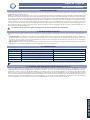
Fig. 1
Fig. 2 Fig. 3

SPRINT 06
Immagini - Images - Images - Imágenes - Bilder - Afbeeldingen
Pag. 2
Immagini - Images - Images - Imágenes - Bilder - Afbeeldingen
Pag. 2
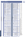
Fig. 5
Fig. 4

SPRINT 06
ITALIANO
Guida per l’installatore
Pagina 1
DICHIARAZIONE CE DI CONFORMITÁ
Fabbricante: GENIUS S.p.A.
Indirizzo: Via Padre Elzi, 32 - 24050 - Grassobbio- Bergamo - ITALIA
Dichiara che: L’apparecchiatura elettronica mod. SPRINT 05
è conforme ai requisiti essenziali di sicurezza delle seguenti direttive CEE:
2006/95/CE direttiva Bassa Tensione.
2004/108/CE direttiva Compatibilità Elettromagnetica
Nota aggiuntiva:
Questo prodotto è stato sottoposto a test in una configurazione tipica omogenea (tutti prodotti di costruzione GENIUS
S.p.A.)
Grassobbio, 10 Settembre 2008
L’Amministratore Delegato
D. Gianantoni
•
•
•
Note per la lettura dell’istruzione
Leggere completamente questo manuale di installazione prima di iniziare l’installazione del prodotto.
Il simbolo
evidenzia note importanti per la sicurezza delle persone e l’integrità dell’automazione.
Il simbolo richiama l’attenzione su note riguardanti le caratteristiche od il funzionamento del prodotto.
INDICE
1. CARATTERISTICHE GENERALI pag.2
2. CARATTERISTICHE TECNICHE pag.2
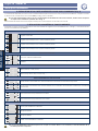
3. LAY-OUT SCHEDA (Fig. 1) pag.2
4. PREDISPOSIZIONI pag.2
5. COLLEGAMENTI E FUNZIONAMENTO pag.3
5.1. CONNETTORE CN1 pag.3
5.2. MORSETTIERA CN2 (Fig. 2) pag.3
5.3. MORSETTIERA CN3 (Fig.3) pag.3
5.4. CONNETTORE CN5 pag.3
6. INSERIMENTO SCHEDA RICEVITORE PER RADIOCOMANDO (Fig. 4) pag.4
7. REGOLAZIONE DEI PARAMETRI DI FUNZIONAMENTO pag.4
8. FUNZIONAMENTO ENCODER pag.5
9. REGOLAZIONE DELLA FORZA MOTORE pag.5
10. LEDS DI CONTROLLO pag.5
11. POSIZIONAMENTO DEI MAGNETI DI FINECORSA (Fig. 5) pag.5
12. LOGICHE DI FUNZIONAMENTO pag.6

SPRINT 06
ITALIANO
Guida per l’installatore
Pagina 2
1. CARATTERISTICHE GENERALI
Vi ringraziamo per aver scelto un nostro prodotto. GENIUS è certa che da esso otterrete tutte le prestazioni necessarie al Vostro
impiego. Tutti i nostri prodotti sono frutto di una pluriennale esperienza nel campo degli automatismi, rafforzata dal fatto di
essere parte del gruppo leader mondiale del settore.
La centrale di comando SPRINT 05 è stata progettata per comandare operatori scorrevoli con una potenza massima di
700W.
Grazie ai controlli di sicurezza attivi e passivi garantisce, se correttamente installata, un’installazione conforme alle vigenti norme
di sicurezza. La possibilità di gestire anche un encoder permette di elevare ulteriormente il livello di sicurezza.
L’elevata semplicità nella programmazione delle principali funzioni permette di ridurre i tempi di installazione.
Grazie ai cinque leds incorporati è in grado di fornire in ogni istante lo stato delle sicurezze e dei finecorsa.
È importante ai fini della sicurezza delle persone seguire tutte le avvertenze e le istruzioni presenti in questo libretto.
Un’errata installazione o un errato uso del prodotto può essere causa di gravi danni alle persone.
Prima di procedere all’installazione del prodotto leggere completamente il presente manuale.
Conservare le istruzioni per riferimenti futuri.
2. CARATTERISTICHE TECNICHE
Tensione di alimentazione 115V~ (+6% -10%) 60Hz
Potenza assorbita 15 W
Carico max. motore 700 W
Carico max. accessori 500 mA
Temperatura ambiente
-20°C +55°C
Fusibili di protezione 2
Logiche di funzionamento Automatica, Manuale
Tempo d’apertura / chiusura 120 sec.
Tempo di pausa Quattro livelli preimpostati
Forza motore Regolabile tramite trimmer
Ingressi in morsettiera
Open A, Open B, Stop, Finecorsa in apertura, Finecorsa in chiusura, Fotocellule,
Alimentazione
Uscite in morsettiera Alimentazione accessori 24V
, Lampeggiante, Motore
Connettore rapido Connettore per riceventi 5 pins, Encoder, Finecorsa, Condensatore
Funzioni programmabili
Logica di funzionamento, Tempo di pausa, Sensibilità frizione, Funzionamento con
encoder, Logica sicurezze, Funzione condominiale
Dimensioni 145 x 105
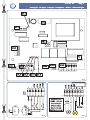
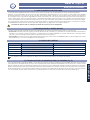
3. LAY-OUT SCHEDA (Fig. 1)
Pos Descrizione Pos Descrizione
CN1 Connettore per encoder F1 Fusibile alimentazione/motore 5A T (5x20)
CN2 Morsettiera bassa tensione F2 Fusibile accessori 0.5A T (5x20)
CN3 Morsettiera alta tensione DL1 Led presenza alimentazione di rete
CN4 Connettore per riceventi DL2 Led stato ingresso FSW
CN5 Connettore per finecorsa DL3 Led stato ingresso STOP
CN6 Connettore per condensatore DL4 Led stato ingresso FCA
TR1 Trimmer regolazione forza motore DL5 Led stato ingresso FCC
DP1 Dip-Switch regolazione parametri
4. PREDISPOSIZIONI
È importante ai fini della sicurezza per le persone seguire attentamente tutte le avvertenze e le indicazioni presenti in
questo libretto. Un’errata installazione o un errato utilizzo del prodotto può essere causa di gravi danni per le perso-
ne.
Verificare che a monte dell’impianto vi sia un adeguato interruttore differenziale, come prescritto dalle normative vigenti,
e prevedere sulla rete di alimentazione un interruttore magnetotermico onnipolare.
Verificare l’esistenza di un adeguato impianto di messa a terra.
Per la messa in opera dei cavi prevedere adeguati tubi rigidi e/o flessibili.
Separare sempre i cavi di alimentazione a 115V~ da quelli di comando a bassa tensione. Per evitare qualsiasi interferenza
si consiglia di utilizzare guaine separate.
•
•
•
•

SPRINT 06
ITALIANO
Guida per l’installatore
Pagina 3
5. COLLEGAMENTI E FUNZIONAMENTO
5.1. CONNETTORE CN1
A questo connettore deve essere collegato l’eventuale encoder. Per il funzionamento dell’encoder far riferimento al para-
grafo 8.
5.2. MORSETTIERA CN2 (Fig. 2)
5.2.1. ALIMENTAZIONE ACCESSORI 24V
Morsetti “+ & -”. A questi morsetti vanno collegati i fili di alimentazione degli accessori a 24V .
Il carico massimo degli accessori non deve superare i 500 mA.
L’uscita di questi morsetti è in corrente continua, rispettare la polarità di alimentazione degli accessori.
5.2.2. OPEN A
Morsetti “OPA & -”. Contatto normalmente aperto. Collegare a questi morsetti un qualsiasi datore d’impulsi (pulsante, selettore
a chiave etc.) che, chiudendo il contatto, genera un’impulso di apertura o chiusura totale del cancello. Il suo funzionamento
è definito tramite il dip-switch 4 (vedi paragrafo 7).
Un impulso di apertura totale ha sempre la precedenza sull’apertura parziale.
Per collegare più datori d’impulso collegare i dispositivi in parallelo.
5.2.3. OPEN B
Morsetti “OPB & -”. Contatto normalmente aperto. Collegare a questi morsetti un qualsiasi datore d’impulsi (pulsante, selettore
a chiave etc.) che, chiudendo il contatto, genera un’impulso di apertura parziale del cancello (apre per 8 secondi).
Un impulso di apertura totale ha sempre la precedenza sull’apertura parziale.
Per collegare più datori d’impulso collegare i dispositivi in parallelo.
5.2.4. FOTOCELLULE
Morsetti “FSW & -”. Contatto normalmente chiuso. A questi morsetti devono essere collegate le fotocellule. Queste possono
funzionare sia come sicurezze in chiusura sia come sicurezze in apertura e chiusura. Il funzionamento viene definito tramite il
dip-switch 5 (vedi paragrafo 8). Lo stato di questo ingresso è segnalato dal led “FSW”.
Si consiglia di non collegare a questi morsetti dispositivi di sicurezza diversi dalle fotocellule.
5.2.5. STOP
Morsetti “STOP & -”. Contatto normalmente chiuso. Collegare a questi morsetti un qualsiasi dispositivo di sicurezza (pulsante,
selettore a chiave, etc...) che deve arrestare il moto del cancello, disabilitando ogni funzione automatica. Solo con un successivo
impulso di apertura totale, il cancello riprende il ciclo memorizzato. Lo stato di questo ingresso è segnalato dal led “STOP”.
Per collegare più datori d’impulso collegare i dispositivi in serie.
5.3. MORSETTIERA CN3 (Fig.3)
5.3.1. MOTORIDUTTORE
Morsetti “APM - CHM - COM” (apre - chiude - comune). Collegare a questi morsetti i cavi di alimentazione del motoriduttore. Il
condensatore deve essere collegato tra i morsetti APM - CHM. Qualora si disponga di un condensatore con morsetto rapido
è possibile utilizzare il connettore CN6, rispettando l’orientamento del morsetto.
5.3.2. LAMPEGGIANTE
Morsetti “LAMP & N”. Collegare a questi morsetti il lampeggiante. L’uscita di questi morsetti è a 115V~.
Il lampeggio non viene dato dalla centrale ma dal lampeggiante.
5.3.3. LINEA
Morsetti “N, F & PE”. Collegare a questi morsetti la linea di alimentazione a 115V~ 60Hz.
Il cavo giallo-verde di messa a terra deve essere collegato al morsetto identificato con la dicitura “PE”.
5.4. CONNETTORE CN5
Il connettore rapido CN5 è dedicato al collegamento dei finecorsa. Il molex del cavo finecorsa più essere innestato solo in
un senso, non esercitare forzature.
Per il corretto funzionamento dell’automazione è assolutamente necessario collegare entrambi finecorsa.

SPRINT 06
ITALIANO
Guida per l’installatore
Pagina 4
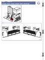
6. INSERIMENTO SCHEDA RICEVITORE PER RADIOCOMANDO (Fig. 4)
La centrale è predisposta per alloggiare un modulo radioricevitore 5 pin. Per procedere all’installazione togliere l’alimentazione
elettrica ed inserire il modulo nell’apposito connettore CN4 (vedi Fig. 1) sulla centrale.
Per non danneggiare, e quindi comprometterne irrimediabilmente il funzionamento, la ricevente deve essere innestata
rispettando l’orientamento di Fig.4
Seguire poi le istruzioni del radioricevitore per la memorizzazione del radiocomando.
7. REGOLAZIONE DEI PARAMETRI DI FUNZIONAMENTO
Tutte le funzioni programmabili della scheda vengono definite agendo sui dip-switch DP1 (vedi Fig.1). Nello schema che segue
sono elencate le diverse possibilità.
LOGICA DI FUNZIONAMENTO
Logica manuale
Logica automatica con 15 secondi di pausa
Logica automatica con 20 secondi di pausa
Logica automatica con 40 secondi di pausa
FUNZIONE CONDOMINIALE
Funzione condominiale disattivata
Funzione condominiale attivata. Durante la fase di apertura ignora successivi impulsi di OPEN.
FUNZIONAMENTO INGRESSO OPEN A
Apre, chiude, apre, chiude, ...
Apre, stop, chiude, stop, apre, stop, ....
FUNZIONAMENTO FOTOCELLULE
Le sicurezze collegate sono attive solo durante il moto in chiusura del cancello
Le sicurezze collegate sono attive sia durante il moto di chiusura che durante il moto di apertura
ENCODER
Funzionamento del cancello senza encoder
Funzionamento del cancello con encoder.
SENSIBILITÀ FRIZIONE ELETTRONICA (attivo solo con encoder collegato ed attivato)
Alta, più sensibile all’ostacolo
Medio-alta
Medio bassa
Bassa, meno sensibile all’ostacolo
Agire sui dip-switch solo dopo aver tolto tensione. In caso contrario si può compromettere il funzionamento della cen-
trale.

SPRINT 06
ITALIANO
Guida per l’installatore
Pagina 5
8. FUNZIONAMENTO ENCODER
La centrale è predisposta per il collegamento di un Encoder (opzionale) che garantisce un livello di sicurezza maggiore.
Durante il funzionamento la forza motore viene gestita direttamente dall’encoder che rileva eventuali ostacoli durante il
movimento del cancello. In caso di ostacoli questo interviene invertendo per due secondi il movimento del cancello, senza
disabilitare l’eventuale richiusura automatica, se inserita. Solo se interviene per due volte consecutive posiziona la centrale
in STOP disabilitando l’eventuale richiusura automatica, questo perché intervenendo per più volte significa che l’ostacolo
permane ed eventuali automatismi potrebbero essere fonte di pericolo. Una volta posizionata in STOP è necessario fornire un
impulso di OPEN A o B per far riprendere il funzionamento normale. La sensibilità d’intervento dell’encoder viene regolata dai
dip-switch 7-8 (vedi paragrafo 7).
L’utilizzo dell’encoder non sostituisce i finecorsa che sono obbligatori.
9. REGOLAZIONE DELLA FORZA MOTORE
La regolazione della forza motore avviene in due modi differenti, a seconda che vi sia collegato o meno l’encoder.
Senza encoder: per regolare la forza motore è necessario agire sul trimmer TR1 (vedi Fig.1) ruotandolo in senso antiorario
per diminuire la forza ed in senso orario per aumentarla. La forza motore deve essere regolata in base alle dimensioni del
cancello, al peso ed agli attriti che questo ha durante il movimento.
Con encoder: La forza motore viene gestita direttamente dall’encoder. Per regolare la sensibilità dell’encoder si deve agire
sui dip-switch 7 e 8 come specificato nel paragrafo 7.
10. LEDS DI CONTROLLO
LED ACCESO SPENTO
DL1 - POWER Centrale alimentata Centrale non alimentata
DL2 - FSW Sicurezze non impegnate Sicurezze impegnate
DL3 - STOP Comando non attivo Comando attivo
DL4 - FCA Finecorsa in apertura libero Finecorsa in apertura impegnato
DL5 - FCC Finecorsa in chiusura libero Finecorsa in chiusura impegnato
In neretto è riportato lo stato dei leds con centrale alimentata e cancello a riposo.
11. POSIZIONAMENTO DEI MAGNETI DI FINECORSA (Fig. 5)
I motoriduttori scorrevoli utilizzano, come finecorsa, un sensore magnetico che lavora abbinato a ue magneti posizionati sulla
cremagliera del cancello. I due magneti sono opportunamente polarizzati ed attivano solo un contatto, quello del finecorsa
di chiusura o quello del finecorsa di apertura. Il magnete che attiva il contatto del finecorsa in apertura riporta raffigurato un
lucchetto aperto, quello che attiva il contatto del finecorsa in chiusura riporta raffigurato un lucchetto chiuso. Per il corretto
funzionamento della centrale il magnete con il lucchetto aperto deve essere posizionato in prossimità del bordo d’apertura
del cancello, viceversa il magnete che raffigura il lucchetto chiuso si deve trovare in corrispondenza del bordo di chiusura
del cancello, vedi figura 5.
•
•

SPRINT 06
ITALIANO
Guida per l’installatore
Pagina 6
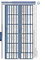
12. LOGICHE DI FUNZIONAMENTO
Logica automatica
Stato cancello
Impulsi
Open A Open B Stop Sicurezze solo in chiusura
Sicurezze in chiusure e
apertura
Chiuso
Apre il cancello e richiude
dopo il tempo di pausa
Apre per 8 secondi e richiude
dopo il tempo di pausa
Se attivo inibisce i comandi
di OPEN
Se attivo inibisce i comandi
di OPEN
Se attivo inibisce i comandi
di Open
Aperto in pausa
Richiude immediatamente il
cancello
Richiude immediatamente Blocca il funzionamento
(2)
Ricarica il tempo di pausa
(3)
Ricarica il tempo di pausa
(3)
In chiusura
Blocca il movimento del can-
cello o inverte
(1)
Nessun effetto Blocca il funzionamento
(2)
Inverte il movimento del
cancello
Blocca il funzionamento ed al
disimpegno inverte il moto
In apertura
Blocca il movimento del can-
cello o inverte
(1)
Inverte il moto del cancello Blocca il funzionamento
(2)
Nessun effetto
Blocca il funzionamento ed al
disimpegno riprende
Logica manuale
Stato cancello
Impulsi
Open A Open B Stop Sicurezze solo in chiusura
Sicurezze in chiusure e
apertura
Chiuso Apre il cancello Apre il cancello per 8 secondi
Se attivo inibisce i comandi
di OPEN
Se attivo inibisce i comandi
di OPEN
Se attivo inibisce i comandi
di OPEN
Aperto in pausa Chiude il cancello Chiude il cancello
Se attivo inibisce i comandi
di OPEN
Se attivo inibisce i comandi
di OPEN
Se attivo inibisce i comandi
di OPEN
In chiusura
Blocca il movimento del can-
cello o inverte
(1)
Nessun effetto Blocca il funzionamento Inverte il moto del cancello
Blocca il funzionamento ed al
disimpegno inverte il moto
In apertura
Blocca il movimento del can-
cello o inverte
(1)
Inverte il moto del cancello Blocca il funzionamento Nessun effetto
Blocca il funzionamento del
cancello ed al disimpegno
riprende
(1) Il comportamento del pulsante Open A viene definito dal Dip-switch 4, vedi paragrafo 7.
(2) L’impulso di Stop blocca il funzionamento del cancello e disabilita tutte le funzioni automatiche selezionate. È necessario un impulso di Open A per far riprendere il ciclo
memorizzato.
(3) Se allo scadere del tempo di pausa programmato la sicurezza è impegnata, al suo disimpegno la centrale ricomincia il conteggio del tempo di pausa programmato.

SPRINT 06
ENGLISH
Guide for the installer
Pagina 7
Notes on reading the instruction
Read this installation manual to the full before you begin installing the product.
The symbol
indicates notes that are important for the safety of persons and for the good condition of the automated
system.
The symbol draws your attention to the notes on the characteristics and operation of the product.
CE DECLARATION OF CONFORMITY
Manufacturer: GENIUS S.p.A.
Address: Via Padre Elzi, 32 - 24050 - Grassobbio- Bergamo - ITALY
Declares that: Control unit mod. SPRINT 05
conforms to the essential safety requirements of the following EEC directives:
2006/95/EC Low Voltage directive.
2004/108/EC Electromagnetic Compatibility directive.
Additional information:
This product underwent a test in a typical uniform configuration (all products manufactured by GENIUS S.p.A.).
Grassobbio, 10 September 2008
Managing Director
D. Gianantoni
•
•
•
INDEX
1. GENERAL CHARACTERISTICS page.8
2. TECHNICAL SPECIFICATIONS page.8
3. BOARD LAY-OUT (Fig. 1) page.8
4. PREPARATIONS page.8
5. CONNECTIONS AND OPERATION page.9
5.1. CN1 CONNECTOR page.9
5.2. TERMINAL BOARD CN2 (Fig. 2) page.9
5.3. TERMINAL BOARD CN3 (Fig. 3) page.9
5.4. CN5 CONNECTOR page.9
6. INSTALLING THE RADIO CONTROL RECEIVER BOARD (Fig. 4) page.10
7. ADJUSTING THE OPERATING PARAMETERS page.10
8. ENCODER OPERATION page.11
9. ADJUSTMENT OF MOTOR POWER page.11
10. CONTROL LEDS page.11
11. POSITIONING THE TRAVEL LIMIT MAGNETS (Fig. 5) page.11
12. FUNCTION LOGICS page.12

SPRINT 06
ENGLISH
Guide for the installer
Pagina 8
1. GENERAL CHARACTERISTICS
Thank you for choosing our product. GENIUS is sure you will get the performances you expect to satisfy your requirements. All
our products are the result of a many years’ experience in the field of the automated systems, strengthened by being part of
a world leading group in this sector.
The SPRINT 05 control unit was designed to command sliding operators with maximum power of 700 W.
Thanks to its active and passive safety controls, it guarantees - if correctly installed - installation conforming to the safety
regulations in force. Encoder control makes it possible to further increase the level of safety.
Extremely simple programming of the main functions reduces installation time.
Thanks to the five integrated LEDs, it can provide at all times the status of the safety devices and travel limit devices.
To ensure people’s safety, all warning and instructions in this booklet must be carefully observed. Incorrect installation
or incorrect use of the product could cause serious harm to people.
Carefully read this manual before installing the product.
Store these instructions for future references.
2. TECHNICAL SPECIFICATIONS
Power supply voltage 115V~ (+6% -10%) 60Hz
Absorbed power 15 W
Motor max. load 700 W
Accessories max. load 500 mA
Operating ambient temperature
-20°C +55°C
Protective fuses 2
Function logics Automatic, Manual
Opening / closing time 120 sec.
Pause time Four preset levels
Motor power Trimmer-adjustable
Terminal board inputs
Open A, Open B, Stop, Travel limit device at opening, Travel limit devices at clos-
ing, Photocells, Power supply
Terminal board outputs 24V
accessories power supply, Flashing lamp, Motor
Rapid connector Connector for 5 pin receivers, Encoder, Travel limit devices Condenser
Programmable functions
Operating logic, Pause time, Clutch sensitivity, Operation with encoder, Safety
devices logic, condo operation
Dimensions 145 x 105
3. BOARD LAY-OUT (Fig. 1)
Pos. Description Pos. Description
CN1 Connector for encoder F1 Power fuse / motor 5A T (5x20)
CN2 Low voltage terminal board F2 Fuse for accessories 0.5A T (5x20)
CN3 High voltage terminal board DL1 LED: Mains power ON
CN4 Receiver connector DL2 LED: FSW input status
CN5 Connector for travel limit device DL3 LED: STOP input status
CN6 Connector for condenser DL4 LED: FCA input status
TR1 Motor power adjustment trimmer DL5 LED: FCC input status
DP1 Parameter adjustment Dip-switches
4. PREPARATIONS
To ensure people’s safety, all warnings and instructions in this booklet must be carefully observed. Incorrect installation
or incorrect use of the product could cause serious harm to people.
Make sure there is an adequate differential switch upstream of the system as specified by current laws, and install a single-
pole thermal breaker on the electric power mains.
Make sure that an adequate earthing system is available.
To lay cables, use adequate rigid and/or flexible tubes.
Always separate 115V~ power cables from low voltage command cables. To prevent any interference whatever, use
separate sheaths.
•
•
•
•
•

SPRINT 06
ENGLISH
Guide for the installer
Pagina 9
5. CONNECTIONS AND OPERATION
5.1. CN1 CONNECTOR
The encoder, if supplied, should be connected to this connector. For encoder operation, consult paragraph 8.
5.2. TERMINAL BOARD CN2 (Fig. 2)
5.2.1. POWER SUPPLY TO 24 V ACCESSORIES
“+ & -” terminals. The accessories 24 V power cables should be connected to these terminals.
The maximum load of the accessories must not exceed 500 mA.
The output of these terminals is - observe the power supply polarity of the accessories.
5.2.2. OPEN A
“OPA & -” terminals. Normally open contact. Connect, to these terminals, any pulse generator (e.g. push-button, key selector,
etc...) which, by closing a contact, commands the gate to totally open or close. The operation of this contact is defined by
dip-switch 4 (see paragraph 7).
A total opening pulse always has priority over partial opening.
To connect several impulse generators, connect the devices in parallel.
5.2.3. OPEN B
“OPB & -” terminals. Normally open contact. Connect, to these terminals, any pulse generator (e.g. push-button, key selector,
etc...) which, by closing a contact, commands the gate to partially open (opens for 8 seconds).
A total opening pulse always has priority over partial opening.
To connect several impulse generators, connect the devices in parallel.
5.2.4. PHOTOCELLS
“FSW & -” terminals. Normally closed contact. The photocells should be connected to these terminals. The photocells
can operate both as closing safety devices and as opening and closing safety devices. Operation is defined by
dip-switch 5 (see paragraph 8). The status of this input is signalled by LED “FSW”.
Do not connect other safety devices (i.e. apart from photocells) to these terminals.
5.2.5. STOP
“STOP & -” terminals. Normally closed contact. Connect, to these terminals, any safety device (push-button, key selector, etc…)
which must stop gate movement, disabling all automatic functions.
The gate resumes its memory-stored cycle only by means of another total opening pulse. The status of this input is signalled
by the “STOP” LED.
To connect several pulse generators, connect the devices in series.
5.3. TERMINAL BOARD CN3 (Fig. 3)
5.3.1. GEARMOTOR
“APM - CHM - COM” terminals (opens – closes -common). Connect the gearmotor power cables to these terminals. Connect
the capacitor between the APM - CHM terminals. If you have a condenser with a rapid terminal, you can use connector CN6,
respecting the fitting direction of the terminal.
5.3.2. FLASHING LAMP
“LAMP & N” terminals. Connect the flashing lamp to these terminals. Output of these terminals is at 115V~.
The flashing is not provided by the control unit but by the flashing lamp.
5.3.3. LINE
“N & F” terminals. Connect power supply line 115V~ 60Hz to these terminals.
The yellow-green ground must be connected to the terminal identified by the words “PE”.
5.4. CN5 CONNECTOR
The CN5 rapid connector is dedicated to the connection of the limit switch. The Molex connector of the limit switch cable can
be connected in one direction only. Do not force.
For a correct operation of the automated system, both limit switches must be connected.

SPRINT 06
ENGLISH
Guide for the installer
Pagina 10
6. INSTALLING THE RADIO CONTROL RECEIVER BOARD (Fig. 4)
The control unit is designed to house a 5-pin radio-receiver module. Installation procedure: turn off power and fit the module
on connector CN4 (see Fig. 1) on the control unit.
To avoid damaging the receiver and thus irreparably compromising its operation, the receiver must be installed, observing
the fitting direction specified in Fig. 4.
This done, observe the radio-receiver instructions to store radio control in the memory.
7. ADJUSTING THE OPERATING PARAMETERS
All the board’s programmable functions are defined by using dip-switch DP1 (see Fig.1). The various options are listed in the
following layout.
FUNCTION LOGIC
Manual logic
Automatic logic with 15 seconds pause
Automatic logic with 20 seconds pause
Automatic logic with 40 seconds pause
CONDO FUNCTION
Condo function disabled
Condo function activated. During opening, it ignores subsequent OPEN impulses
OPEN A INPUT OPERATION
Opens, closes, opens, closes, ...
Opens, stops, closes, stops, opens, stops, ....
PHOTOCELL OPERATION
The connected safety devices are active only during the gate closing movement
The connected safety devices are active both during the closing movement and the opening move-
ment
ENCODER
Gate operation without encoder
Gate operation with encoder.
ELECTRONIC CLUTCH SENSITIVITY (active only with the encoder connected and activated)
High, more sensitive to the obstacle
Medium-high
Medium Low
Low, less sensitive to the obstacle
Use the dip-switches only after cutting power. Otherwise, the operation of the control unit could be compromised.

SPRINT 06
ENGLISH
Guide for the installer
Pagina 11
8. ENCODER OPERATION
The control unit is designed for connection to an Encoder (optional) which guarantees a higher level of safety.
During operation, motor power is managed directly by the encoder, which detects any obstacles while the gate is moving. In
case of obstacles, the encoder intervenes, reversing gate movement for two seconds, without disabling automatic closure if
input. Only if the encoder intervenes two consecutive times, it locates the control unit in STOP position, disabling any automatic
re-closure, because if the encoder intervenes several times, this means that the obstacle remains and any automatic move-
ments could be a source of danger. When it is in STOP position, an OPEN A or B impulse must be provided, to resume normal
operation. The sensitivity of encoder intervention is adjusted by dip-switches 7-8 (see paragraph 7).
Use of the encoder does not replace the travel limit devices, which are compulsory.
9. ADJUSTMENT OF MOTOR POWER
Motor power is adjusted in two difference ways, depending on whether or not the encoder is connected.
Without encoder: To adjust motor power, use trimmer TR1 (see Fig.1) turning it anti-clockwise to reduce power and clock-
wise to increase it. Motor force must be adjusted according to the size of the gate, to the weight and to the friction during
movement.
With encoder: Motor power is managed directly by the encoder. Use dip-switches 7 and 8 to adjust encoder sensitivity as
specified in paragraph 7.
10. CONTROL LEDS
LED ON OFF
DL1 - POWER Control unit powered Control unit not powered
DL2 - FSW Safety devices not engaged Safety devices engaged
DL3 - STOP Command not active Command active
DL4 - FCA Opening travel limit device free Opening travel limit device engaged
DL5 - FCC Closing travel limit device free Closing travel limit device engaged
Status of LEDs, with control unit powered and gate at rest shown in bold.
11. POSITIONING THE TRAVEL LIMIT MAGNETS (Fig. 5)
Sliding gearmotors use, as travel limits, a magnetic sensor that operates together with two magnets positioned on the gate
rack. Both magnets are suitably polarized and activate a contact only: the contact of the closing travel limit or the contact
of the opening travel limit. The magnet that activates the contact of the opening travel limit device is marked with an open
padlock, the contact that activates the closing travel limit is marked with a closed padlock. For the correct operation of the
control unit, the magnet with an open padlock must be positioned near the gate opening edge, vice versa the magnet with
the closed padlock must be positioned near the gate closing edge (see fig. 5).
•
•

SPRINT 06
ENGLISH
Guide for the installer
Pagina 12
12. FUNCTION LOGICS
Automatic logic
Gate status
Pulses
Open A Open B Stop Safety devices only at closure
Opening and closing safety
devices
Closed
Opens gate and recloses
it after pause time
Opens for 8 seconds and
closes after pause time
If active, it disables the
OPEN commands
If active, it disables the
OPEN commands
If active, it disables the
OPEN commands
Open in pause Closes the gate immediately Closes immediately Stops operation
(2)
Recharges pause time
(3)
Recharges pause time
(3)
At closure
Blocks gate movement
or reverses it
(1)
No effect Stops operation
(2)
Reverses gate movement
Stops operation and reverses
motion after release
At opening
Blocks gate movement
or reverses it
(1)
Reverses gate movement Stops operation
(2)
No effect
Stops operation and restarts
after release
Manual logic
Gate status
Pulses
Open A Open B Stop Safety devices only at closure
Opening and closing safety
devices
Closed Opens the gate Opens the gate for 8 seconds
If active, it disables the
OPEN commands
If active, it disables the
OPEN commands
If active, it disables the
OPEN commands
Open in pause Closes the gate Closes the gate
If active, it disables the
OPEN commands
If active, it disables the
OPEN commands
If active, it disables the
OPEN commands
At closure
Blocks gate movement
or reverses it
(1)
No effect Stops operation Reverses gate movement
Stops operation and reverses
motion after release
At opening
Blocks gate movement
or reverses it
(1)
Reverses gate movement Stops operation No effect
Stops gate operation and
restarts after release
(1) The behaviour of Open A push-button is defined by Dip-switch 4 - see parag.7.
(2) The Stop impulse blocks gate operation and disables all selected automatic functions. An Open A impulse is necessary to resume the saved cycle.
(3) If the safety device is engaged when the programmed pause time elapses, when it is released, the control unit resumes counting the programmed pause time.

SPRINT 06
FRAN
Ç
AIS
Guide pour l’installateur
Pagina 13
DÉCLARATION CE DE CONFORMITÉ
Fabricant: GENIUS S.p.A.
Adresse: Via Padre Elzi, 32 - 24050 - Grassobbio- Bergamo - ITALIE
Déclare que: L’armoire électronique mod. SPRINT 05
est conforme aux exigences essentielles de sécurité des directives CEE suivantes:
2006/95/CE directive Basse Tension.
2004/108/CE directive Compatibilité Électromagnétique.
Note supplémentaire:
Ce produit a été testé dans une configuration typique homogène (tous les produits sont fabriqués par GENIUS S.p.A.)
Grassobbio, le 10 septembre 2008
L’Administrateur Délégué
D. Gianantoni
•
•
•
Remarques pour la lecture de l’instruction
Lire ce manuel d’installation dans son ensemble avant de commencer l’installation du produit.
Le symbole
souligne des remarques importantes pour la sécurité des personnes et le parfait état de l’automatisme.
Le symbole attire l’attention sur des remarques concernant les caractéristiques ou le fonctionnement du produit.
INDEX
1. CARACTÉRISTIQUES GÉNÉRALES page.14
2. CARACTÉRISTIQUES TECHNIQUES page.14
3. SCHÉMA DE LA CARTE (Fig. 1) page.14
4. PRÉDISPOSITIONS page.14
5. CONNEXIONS ET FONCTIONNEMENT page.15
5.1. CONNECTEUR CN1 page.15
5.2. BORNIER CN2 (Fig. 2) page.15
5.3. BORNIER CN3 (Fig. 4) page.15
5.4. CONNECTEUR CN5 page.15
6. INSTALLATION DE LA CARTE DU RÉCEPTEUR POUR RADIOCOMMANDE (Fig. 4) page.16
7. RÉGLAGE DES PARAMÈTRES DE FONCTIONNEMENT page.16
8. FONCTIONNEMENT DE L’ENCODEUR page.17
9. RÉGLAGE DE LA FORCE DU MOTEUR page.17
10. LEDS DE CONTRÔLE page.17
11. POSITIONNEMENT DES AIMANTS DE FIN DE COURSE (Fig. 5) page.17
12. LOGIQUES DE FONCTIONNEMENT page.18

SPRINT 06
FRANÇAIS
Guide pour l’installateur
Pagina 14
1. CARACTÉRISTIQUES GÉNÉRALES
Nous vous remercions d’avoir choisi un de nos produits. La société GENIUS est certaine qu’il vous permettra d’obtenir toutes les
performances nécessaires pour l’usage que vous avez prévu. Tous nos produits sont le fruit d’une longue expérience dans le
domaine des automatismes, renforcée par le fait que la société appartient au groupe leader mondial du secteur.
La centrale de commande SPRINT 05 a été conçue pour commander des opérateurs coulissants à la puissance maximale
de 700 W.
Grâce aux contrôles de sécurité actifs et passifs, elle garantit, si le montage est correct, une installation conforme aux règles
de sécurité en vigueur. La possibilité de gérer également un encodeur permet d’élever ultérieurement le niveau de sécurité.
La très grande simplicité de programmation des principales fonctions permet de réduire les temps d’installation.
Grâce aux cinq LEDs incorporées, elle est en mesure de fournir à tout moment l’état des sécurités et des fins de course.
Pour la sécurité des personnes, il est important de suivre tous les avertissements et les instructions figurant dans cette
brochure. Une installation ou un usage erronés du produit peut provoquer de sérieuses blessures aux personnes.
Avant de commencer l’installation du produit, lire attentivement le présent manuel.
Conserver les instructions pour toute référence future.
2. CARACTÉRISTIQUES TECHNIQUES
Tension d’alimentation 115V~ (+6% -10%) 60Hz
Puissance absorbée 15 W
Charge maxi moteur 700 W
Charge maxi accessoires 500 mA
Température de fonctionnement
-20°C +55°C
Fusibles de protection 2
Logiques de fonctionnement Automatique, Manuel
Temps d’ouverture/fermeture 120 s.
Temps de pause Quatre niveaux présélectionnés
Force du moteur Réglable par trimmer
Entrées bornier
Open A, Open B, Stop, Fin de course en ouverture, Fin de course en fermeture,
Photocellules, Alimentation
Sorties bornier Alimentation des accessoires 24V
, Lampe Clignotante, Moteur
Connecteur rapide
Connecteur pour récepteurs 5 broches, Encodeur, Fin de course,
Condensateur
Fonctions programmables
Logique de fonctionnement, Temps de pause Sensibilité de l’embrayage, Fonc-
tionnement avec encodeur, Logique sécurités, Fonction collective
Dimensions 145 x 105
3. SCHÉMA DE LA CARTE (Fig. 1)
Rep. Description Rep. Description
CN1 Connecteur pour encodeur F1 Fusible alimentation/moteur 5A T (5x20)
CN2 Bornier basse tension F2 Fusible accessoires 0.5A T (5x20)
CN3 Bornier haute tension DL1 LED de présence de courant
CN4 Connecteur pour récepteurs DL2 LED d’état entrée FSW
CN5 Connecteur pour fin de course DL3 LED d’état entrée STOP
CN6 Connecteur pour condensateur DL4 LED d’état entrée FCA
TR1
Trimmer de réglage de la force du moteur
DL5 LED d’état entrée FCC
DP1
DIP-SWITCHE de réglage des paramètres
4. PRÉDISPOSITIONS
Pour la sécurité des personnes, il est important de suivre attentivement tous les avertissements et les indications figurant dans
ce livret. Une installation ou une utilisation erronée du produit peut provoquer de graves blessures aux personnes.
Vérifier qu’un interrupteur différentiel approprié soit placé en amont de l’installation conformément aux normes en vigueur
et prévoir un interrupteur magnétothermique à interruption multipolaire sur le réseau d’alimentation.
Vérifier l’existence d’une installation adéquate de mise à la terre.
Prévoir des tubes rigides et/ou flexibles pour la pose des câbles.
Toujours séparer les câbles d’alimentation 115V~ des câbles de commande basse tension. Pour éviter toute interférence,
on conseille d’utiliser des gaines séparées.
•
•
•
•

SPRINT 06
FRAN
Ç
AIS
Guide pour l’installateur
Pagina 15
5. CONNEXIONS ET FONCTIONNEMENT
5.1. CONNECTEUR CN1
Brancher sur ce connecteur l’éventuel encodeur. Pour le fonctionnement de l’encodeur, voir le paragraphe 8.
5.2. BORNIER CN2 (Fig. 2)
5.2.1. ALIMENTATION DES ACCESSOIRES 24VCC
Bornes “+ & -”. Connecter à ces bornes les fils d’alimentation des accessoires à 24Vcc.
La charge maximum des accessoires ne doit pas dépasser 500mA.
La sortie de ces bornes est en courant continu, respecter la polarité d’alimentation des accessoires.
5.2.2. OPEN A
Bornes “OPA & -”. Contact normalement ouvert. Connecter à ces bornes un générateur d’impulsions quelconque (bouton-
poussoir, sélecteur à clé, etc...) qui, en fermant le contact, génère une impulsion d’ouverture ou de fermeture totale du portail.
Son fonctionnement est défini par le DIP-SWITCHE 4 (voir paragraphe 7).
Une impulsion d’ouverture totale est toujours prioritaire par rapport à l’ouverture partielle.
Pour connecter plusieurs générateurs d’impulsions, connecter les dispositifs en parallèle.
5.2.3. OPEN B
Bornes “OPB & -”. Contact normalement ouvert. Connecter à ces bornes un générateur d’impulsions quelconque (bouton-
poussoir, sélecteur à clé, etc...) qui, en fermant le contact, génère une impulsion d’ouverture partielle du portail (ouvre pendant
8 secondes).
Une impulsion d’ouverture totale est toujours prioritaire par rapport à l’ouverture partielle.
Pour connecter plusieurs générateurs d’impulsions, connecter les dispositifs en parallèle.
5.2.4. PHOTOCELLULES
Bornes “FSW & -”. Contact normalement fermé. Connecter à ces bornes les photocellules. Celles-ci peuvent fonctionner comme
des sécurités en fermeture et comme des sécurités en ouverture et fermeture. Le fonctionnement est défini par le DIP-SWITCHE
5 (voir paragraphe 8). L’état de cette entrée est signalé par la LED “FSW”.
On conseille de ne pas connecter à ces bornes des dispositifs de sécurité différents des photocellules.
5.2.5. STOP
Bornes “STOP & -”. Contact normalement fermé. Connecter à ces bornes un dispositif de sécurité quelconque
(bouton-poussoir, sélecteur à clé, etc...) qui doit arrêter le mouvement du portail, invalidant toute fonction automatique.
Seule une impulsion successive d’ouverture totale permet au portail de reprendre le cycle mémorisé. L’état de cette entrée
est signalé par la LED “STOP”.
Pour connecter plusieurs générateurs d’impulsions, connecter les dispositifs en série.
5.3. BORNIER CN3 (Fig. 4)
5.3.1. MOTORÉDUCTEUR
Bornes “APM - CHM - COM” (ouvre - ferme - commun). Connecter à ces bornes les câbles d’alimentation du motoréducteur.
Le condensateur doit être connecté entre les bornes APM - CHM. Si l’on dispose d’un condensateur avec une borne rapide,
on peut utiliser le connecteur CN6, en respectant l’orientation de la borne.
5.3.2. LAMPE CLIGNOTANTE
Bornes “LAMP & N”. Connecter à ces bornes la lampe clignotante. La sortie de ces bornes est à 115V~.
Le clignotement n’est pas transmis par la centrale mais par la lampe clignotante.
5.3.3. LIGNE
Bornes “N & F”. Connecter à ces bornes la ligne d’alimentation à 115V~ 60Hz.
La terre jaune-vert doit être relié à la borne identifiée par les mots «PE».
5.4. CONNECTEUR CN5
Le connecteur rapide CN5 est destiné à la connexion des fins de course. Le molex du câble des fin de course peut être em-
broché dans un seul sens, ne pas forcer.
Pour le fonctionnement correct de l’automatisme, il est absolument nécessaire de connecter les deux fins de course.

SPRINT 06
FRANÇAIS
Guide pour l’installateur
Pagina 16
6. INSTALLATION DE LA CARTE DU RÉCEPTEUR POUR RADIOCOMMANDE (Fig. 4)
La centrale est disposée pour recevoir un module radiorécepteur à 5 broches. Pour procéder à l’installation, couper le courant
et brancher le module sur le connecteur CN4 (voir Fig.1) sur la centrale.
Pour ne pas endommager et donc ne pas compromettre irrémédiablement le fonctionnement, embrocher le récepteur
en respectant l’orientation spécifiée dans la Fig. 4
Suivre ensuite les instructions du récepteur radio pour la mémorisation de la radiocommande.
7. RÉGLAGE DES PARAMÈTRES DE FONCTIONNEMENT
Toutes les fonctions programmables de la carte sont définies en agissant sur le DIP-SWITCHE DP1 (voir Fig.1). Le schéma suivant
présente les différentes possibilités.
LOGIQUE DE FONCTIONNEMENT
Logique manuelle
Logique automatique avec 15 secondes de pause
Logique automatique avec 20 secondes de pause
Logique automatique avec 40 secondes de pause
FONCTION COLLECTIVE
Fonction collective désactivée
Fonction collective activée. Durant la phase d’ouverture, elle ignore les impulsions successives
d’OPEN
FONCTIONNEMENT ENTRÉE OPEN A
Ouvre, ferme, ouvre, ferme, ...
Ouvre, stop, ferme, stop, ouvre, stop, ....
FONCTIONNEMENT DES PHOTOCELLULES
Les sécurités connectées sont actives durant le mouvement en fermeture du portail
Les sécurités connectées sont actives durant le mouvement de fermeture et durant le mouvement
d’ouverture
ENCODEUR
Fonctionnement du portail sans encodeur
Fonctionnement du portail avec encodeur.
SENSIBILITÉ DE L’EMBRAYAGE ÉLECTRONIQUE (actif uniquement si l’encodeur est connecté et activé)
Haute, plus sensible à l’obstacle
Moyenne-haute
Moyenne faible
Faible, moins sensible à l’obstacle
Agir sur les DIP-SWITCHES uniquement après avoir coupé le courant. Dans le cas contraire, le fonctionnement de la
centrale peut être compromis.
La page charge ...
La page charge ...
La page charge ...
La page charge ...
La page charge ...
La page charge ...
La page charge ...
La page charge ...
La page charge ...
La page charge ...
La page charge ...
La page charge ...
La page charge ...
La page charge ...
La page charge ...
La page charge ...
La page charge ...
La page charge ...
La page charge ...
La page charge ...
La page charge ...
La page charge ...
La page charge ...
La page charge ...
-
 1
1
-
 2
2
-
 3
3
-
 4
4
-
 5
5
-
 6
6
-
 7
7
-
 8
8
-
 9
9
-
 10
10
-
 11
11
-
 12
12
-
 13
13
-
 14
14
-
 15
15
-
 16
16
-
 17
17
-
 18
18
-
 19
19
-
 20
20
-
 21
21
-
 22
22
-
 23
23
-
 24
24
-
 25
25
-
 26
26
-
 27
27
-
 28
28
-
 29
29
-
 30
30
-
 31
31
-
 32
32
-
 33
33
-
 34
34
-
 35
35
-
 36
36
-
 37
37
-
 38
38
-
 39
39
-
 40
40
-
 41
41
-
 42
42
-
 43
43
-
 44
44


dans d''autres langues
- italiano: Genius SPRINT 06 Istruzioni per l'uso
- español: Genius SPRINT 06 Instrucciones de operación
- Deutsch: Genius SPRINT 06 Bedienungsanleitung
- Nederlands: Genius SPRINT 06 Handleiding
Documents connexes
-
Genius SPRINT 05 SW Mode d'emploi
-
-
-
-
-
-
-
-
Genius BRAIN03 BRAIN04 Mode d'emploi
-