Hilti GX 100 Mode d'emploi
- Catégorie
- Outils électroportatifs
- Taper
- Mode d'emploi

GX 100
Operating instructions en
Mode d’emploi fr
zh
ja
ko
Printed: 07.07.2013 | Doc-Nr: PUB / 5069871 / 000 / 00

GX
1
00
GX 100
R
13
11
10
1
12
R
GX 1
0
0
3
7
4
8
5
6
9
2
9
14
1
G
햾
Printed: 07.07.2013 | Doc-Nr: PUB / 5069871 / 000 / 00

2
3
1
2
1
2
3
4
G
X
1
0
0
G
X
1
0
0
R
GX 100
GX 100
R
5
GX 100
GX 100
1
2
6
3
5
4
6
GX 100
GX 100
1
3
2
7
1
3
2
8
1
3
2
9
1
2
3
Printed: 07.07.2013 | Doc-Nr: PUB / 5069871 / 000 / 00

1
2
10
3
1
2
11
12
G
XGX 100
1
14
1
15
1
2
13
3
1
2
Printed: 07.07.2013 | Doc-Nr: PUB / 5069871 / 000 / 00

1
en
It is essential that the operating instructions
are read before the tool is operated for the
first time.
Always keep these operating instructions
together with the tool.
Ensure that the operating instructions are
with the tool when it is given to other per-
sons.
GX 100 gas-powered fastening tool
Contents Page
1. General information 1
2. Description 2
3. Accessories and consumables 2
4. Technical data 3
5. Safety precautions 3
6. Before use 5
7. Operation 6
8. Care and maintenance 8
9. Troubleshooting 8
10. Disposal 11
11. Manufacturer's warranty – tools 11
12. CE declaration of conformity 12
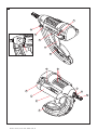
Parts of the tool
햲 Grip
햳 Lockbutton
햴 Nosepiece
햵 Sliding sleeve
햶 Magazine
햷 Type plate
햸 Gas can compartment
햹 Gas can compartment cover
햺 Ventilation slots
햻 Locking lever
햽 Trigger
햾 Reset button
햿 Nail pusher
헀 Belt hook
The numbers refer to the illustrations. The illustra-
tions can be found on the fold-out cover pages. Keep
these pages open while you read the operating instruc-
tions.
In these operating instructions, the designation “the tool”
always refers to the GX 100 gas-powered fastening tool.
Location of identification data on the tool
The type designation and serial number are printed on
the type plate on the tool. Make a note of this informa -
tion in your operating instructions and always refer to it
when making an enquiry to your Hilti representative or
service department.
Type: GX100
Serial no.:
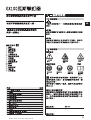
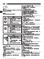
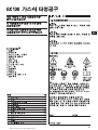
Warning signs
General
warning
Warning:
explosive substance
Warning:
hot surface
Obligation signs
Wear a hard
hat
Wear ear
protection
Wear eye
protection
Read the operating
instructions before
use.
Symbols
1. General information
1.1 Signal words and their meaning
-WARNING-
The word WARNING is used to draw attention to a poten-
tially dangerous situation which could lead to severe per -
sonal injury or death.
-CAUTION-
The word CAUTION is used to draw attention to a potentially
dangerous situation which could lead to minor person-
al injury or damage to the equipment or other property.
-NOTE-
The word NOTE is used to indicate instructions and oth-
er useful information. It is not used to indicate potentially
dangerous situations or situations where damage may
occur.
1.2 Pictograms
Printed: 07.07.2013 | Doc-Nr: PUB / 5069871 / 000 / 00

2
en
2. Description
The tool is designed for driving specially manufactured
nails (fasteners) into concrete, steel and other materials
suitable for the direct fastening technique (please refer
to the Fastening Technology Manual). The piston princi-
ple employed ensures maximum operating safety and
fastening reliability . Gas is used as a propellant.
The tool, gas can, valve head and fasteners form a sin-
gle technical unit. This means that the tool can achieve
optimum fastening performance only when used in con-
junction with the Hilti fasteners and gas cans specially
designed and manufactured for it. The fastening and
application recommendations given by Hilti apply only
when these conditions are observed.
2.1 Piston principle
The energy from the propellant charge is transferred to
a piston, the accelerated mass of which drives the fas-
tener into the base material. As approximately 95 % of
the kinetic energy is absorbed by the piston, the fasten-
er is driven into the base material at much reduced veloc-
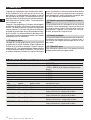
3. Accessories and consumables
Gas can with black valve head GC 11 / GC 12 Standard
Gas can with gray valve head GC 11 HA / GC 12 HA
> 1200 m (3900 ft) and/or high fastener driving rate
Nosepiece X-100 TN
Magazine X-GM 40
Support X-100 SL
Heat shield X-100 HP
Punch X-100 NP
Nails Length In magazine strips of Suitable base materials
X-EGN 14 MX 14 mm (
1
/
2
″) 10 Steel
X-GHP 18 MX 18 mm (
11
/
16
″) 10 Hard concrete / pre-cast concrete / steel
X-GN 20 MX 20 mm (
3
/
4
″) 10 Concrete / masonry with plaster coating (1cm) /
sand-lime blocks / concrete blocks
X-GN 27 MX 27 mm (1″) 10 Concrete / masonry with plaster coating (1cm) /
sand-lime blocks / concrete blocks
X-GN 32 MX 32 mm (1
1
/
4
″) 10 Concrete / masonry with plaster coating (1cm) /
sand-lime blocks / concrete blocks
X-GN 39 MX 39 mm (1
9
/
16
″) 10 Concrete / masonry with plaster coating (1cm) /
sand-lime blocks / concrete blocks
ity (less than 100 m/sec.) in a controlled manner. The
fastener driving process ends when the piston reaches
the end of its travel. This makes dangerous through-shots
virtually impossible when the tool is used correctly .
2.2 Drop-firing safety device
The drop-firing safety device is the result of coupling the
firing mechanism with the cocking movement. This pre-
vents the tool from firing when dropped onto a hard sur -
face, no matter at which angle the impact occurs.
2.3 Trigger safety device
The trigger safety device ensures that a fastener cannot
be driven simply by pulling the trigger only . The tool must
be pressed against a firm surface before a fastener can
be released.
2.3.1 Contact pressure safety device
The tool can be fired only when pressed against a firm
surface with a significant force.
Printed: 07.07.2013 | Doc-Nr: PUB / 5069871 / 000 / 00

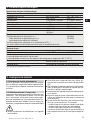
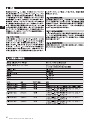
4. Technical data
Tool with magazine and gas can
Weight 3.95 kg (8.7 lbs)
Dimensions (L×W×H) 425×172×370 mm (16
3
/
4
″×6
3
/
4
″×14
1
/
2
″)
Nail length max. 39 mm max. (1
9
/
16
″)
Nail diameter 3.0 mm and 2.6 mm (쏗118 and 쏗102 in)
Magazine capacity 40 + 2 nails
Contact movement approx. 36 mm (1
7
/
16
″)
Contact pressure approx. 120 N (27 lbs)
Operating temperature range / ambient temperature –5°C to 45°C (23°F to 113°F)
Max. fastener driving rate 600 per 30 min.
1000 per hour
Noise information (applicable to 1mm sheet metal on B45 concrete):
1b) Noise (power) level L
WA, 1S
109 dB (A)
Workplace-relevant emission value L
pAImax
102 dB (A)
(measured at operator ear level)
1e) Noise (pressure) level L’
–
pA, 1s
96 dB (A)
(Variations in operating conditions may cause deviation from these noise emission values.)
Gas can
Capacity 1 can for 750 nails
Recommended transport and storage temperature +5°C to +25°C (41°F to 77°F)
The gas can is pressurized.
Avoid prolonged exposure to direct sunlight.
Never expose the gas can to temperatures over 50°C (122°F).
Substances contained Dimethyl ether, isobutane, propylene,
propane, butane, ethanol and isoparaffin
Gas can Not refillable
Right of technical changes reserved.
3
en
5. Safety precautions
5.1 Basic safety instructions
In addition to the safety precautions listed in the indi-
vidual sections of these operating instructions, the fol-
lowing points must be strictly observed at all times.
5.2 Use as intended
The tool is intended mainly for professional use. It designed
for driving nails into concrete, steel, sand-lime block,
concrete block masonry and masonry with a plaster or
cement rendering finish when installing drywall parti-
tions and for other suitable fastening applications in the
construction industry and associated trades.
G Manipulation or modification of the tool is not per-
missible.
G To avoid the risk of injury, use only original Hilti acces-
sories and consumables.
G Observe the information printed in the operating instruc-
tions concerning operation, care and maintenance.
G Never point the tool at yourself or at any bystander.
G Never press the nosepiece of the tool against your hand
or other part of your body (or other person’s hand or
parts of their body).
G Do not attempt to drive fasteners into unsuitable mate-
rials:
- Materials that are too hard, e.g. welded steel and cast
iron
- Materials that are too soft, e.g. wood and drywall
panel
- Materials that are too brittle, e.g. glass and ceramic
tiles
Driving a nail into these materials may cause the nail
to break, shatter or to be driven right through.
Printed: 07.07.2013 | Doc-Nr: PUB / 5069871 / 000 / 00

4
en
G The tool and its ancillary equipment may present haz-
ards when used incorrectly by untrained personnel or
not as directed.
G Pull the trigger only when the nosepiece of the tool is
in contact with the base material.
G Always hold the tool securely, perpendicular to the
work surface. This will reduce the possibility of the nail
ricocheting off the work surface.
G Never redrive a fastener. This may cause the fastener
to break or shatter.
G Never drive a fastener into an existing hole, except as
recommended by Hilti.
G Always observe the application guidelines.
5.3 Take the necessary precautions to make the
workplace safe
G Wear non-slip shoes.
G Always ensure that you have a secure stance and keep
your balance at all times.
G Avoid unfavorable body positions.
G Do not expose the tool to rain or snow and do not use
it in wet or damp environments or in the vicinity of
inflammable liquids or gasses.
G Ensure that the working area is well lit.
G Operate the tool only in well-ventilated working areas.
G Objects which could cause injury should be removed
from the working area.
G The tool is for hand-held use only.
G Keep the arms flexed when the tool is fired (do not
straighten the arms).
G Keep other persons, children in particular, outside the
working area.
G Before using the tool, make sure that no one is stand-
ing behind or below the point where fasteners are to
be driven.
G Keep the grip dry, clean and free from oil and grease.
5.4 General safety precautions
G Operate the tool only as directed and only when it is in
faultless condition.
G Never leave the tool unattended when it is loaded.
G Always unload the tool before beginning cleaning, ser-
vicing or changing parts and before work breaks (remove
the gas can and nails).
G When not in use, the tool must be unloaded and stored
separate from the gas can in a dry, locked place or
where it is out of reach of children.
G Remove the gas can before transporting the tool.
G Do not use the tool if parts of it are damaged or broken.
5.4.1 Mechanical
G Use only nails that have been approved for use with
the tool.
G Do not load nails into the magazine when it is not cor-
rectly attached to the tool. The nails may be forcibly
ejected.
5.4.2 Thermal
G Allow the tool to cool when it becomes hot.
G Do not exceed the maximum fastener driving rate (num-
ber of fasteners driven per given time interval). The
tool may otherwise overheat.
5.4.3 Gas
-WARNING-
Liquid gas under pressure.
Observe the hazard warnings and first-aid instructions
printed on the gas can.
The gas is highly inflammable (contains dimethyl ether,
isobutane, propene, propane, butane, ethanol and iso-
paraffin).
The gas can cannot be refilled.
G Do not use a gas can if it has been damaged.
G Donotattempttoopenagascan.
G Never spray the gas toward persons or animals.
G Keep the gas away from all sources of ignition such as
naked flames, sparks, pilot lights, static discharge and
very warm surfaces.
G Do not smoke while using the tool.
G Do not attempt to force the gas can open. Do not incin-
erate or crush the can and do not attempt to reuse it
for any other purpose.
Storage
G Do not store gas cans in inhabited rooms or in rooms
connected to inhabited rooms.
G Store the gas cans in a dry , well-ventilated place.
G Store the gas cans out of reach of children.
G Do not expose gas cans to direct sunlight or temper-
atures above 50°C (122°F).
G Recommended storage temperature: 5°C to 25°C (41°F
to 77°F).
First aid
-WARNING-
G Direct skin contact with the liquid gas may cause
chilblains or a serious freezing injury similar to a burn.
G If the gas has been inhaled, the person affected should
be taken into the open air and brought into a comfort-
able position.
G In case of unconsciousness, bring the person affect-
ed into a secure recovery position. Should the person
stop breathing, apply artificial respiration and supply
oxygen if necessary .
G In case of gas contact with the eyes: Rinse the open
eyes under running water for one minute.
Printed: 07.07.2013 | Doc-Nr: PUB / 5069871 / 000 / 00

5
en
G In case of gas contact with the skin: Wash the contact
surface carefully with warm water and soap and apply
a skin cream when dry .
G Consult a doctor if necessary .
5.5 Requirements to be met by users
G The tool is intended for professional use.
G The tool may be operated, serviced and repaired only
by authorized, trained personnel. This personnel must
be informed of any special hazards that may be encoun-
tered.
G Always concentrate on your work. Proceed carefully
and do not use the tool if your full attention is not on
the job.
5.6 Personal protective equipment
G The operator and other persons in the immediate vicin-
ity must always wear eye protection, a hard hat and
ear protection while the tool is in use or when check-
ing the tool in case of a fault.
5.7 Safety devices
G Never use the tool if the sliding sleeve (safety device)
is damaged or missing.
6. Before use
-WARNING-
The magazine must be empty.
The gas can must be removed from the can compart-
ment.
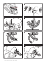
6.1 Inserting nails
1. Pull the nail pusher back until it engages.
-NOTE-
The nail pusher must engage.
2. Slide the nails into the magazine (maximum of 4 strips
of 10 nails).
3. Disengage the nail pusher and allow it to slide forward
slowly.
6.2 Preparing the gas can for use
1. Position the valve head on the inside edge of the gas
can.
2. Press the valve head onto the valve seat until it engages.
-NOTE-
Check that the valve head is fitted correctly on the valve
seat. Slight play is normal.
-CAUTION-
Once the valve head has been fitted to the valve seat on
the gas can it should not be removed (except when the
can is disposed of).
6.3 Inserting the gas can
1. Open the cover of the gas can compartment on the
tool.
2. Slide the gas can into the can compartment, base first,
until it engages.
-NOTE-
The arrow on the valve head must point to the outside
and the white plate must be positioned toward the tool.
3. Close the cover of the gas can compartment and ensure
that it engages in the closed position.
Printed: 07.07.2013 | Doc-Nr: PUB / 5069871 / 000 / 00

6
en
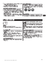
-WARNING-
G Driving the nail may cause flying frag-
ments.
G Flying fragments may injure parts of
the body or the eyes.
G Wear eye protection and a hard hat.
GX 100
GX 100
R
-WARNING-
G Making the tool ready to fire by press-
ing it against a part of the body (e.g.
the hand) is not permissible.
G This could cause a nail to be driven
into a part of the body.
G Never press the tool against a part of
the body .
-CAUTION-
G The nail is driven by the energy released
on ignition of a gas-air mixture.
G An excessively high noise level may
damage the hearing.
G Wear ear protection.
7. Operation
-NOTE-
When holding the tool with the second hand, care must
be taken to position the hand so that no ventilation slots
or openings are covered.
-CAUTION-
Never attempt to redrive the same fastener.
7.1 Operation
-NOTE-
The magazine must contain at least 2 nails, otherwise no
nail can be driven.
1. Hold the tool at right angles to the work surface and
then press it against the surface as far as it will go.
2. Drive the fastener by pulling the trigger.
7.2 The magazine
-NOTE-
The tool must be unloaded each time before the maga-
zine is changed (see 7.6).
7.2.1 Removing the magazine
1. Pull the nail pusher back until it engages.
-NOTE-
The nail pusher must engage correctly .
2. Remove all nails from the magazine.
3. Disengage the nail pusher and allow it to slide forward
slowly.
4. Push the locking lever down toward the magazine.
5. Swing the magazine forwards away from the tool.
6. Detach the magazine from the tool.
7.2.2 Fitting the magazine
1. Attach the front end of the magazine to the tool.
-NOTE-
The locking lever must be in the open position.
2. Swing the magazine toward the tool, taking care to
ensure that its contours match the shape of the tool.
3. Close the locking lever and check that it engages
securely.
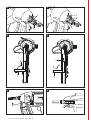
7.3 Adjusting the fastener driving depth at the
nosepiece of the tool
-NOTE-
G When the red ring is not visible, the nosepiece is set
to the standard fastener driving depth (standard set-
ting for fastening wood to concrete).
G When the red ring is visible, the nosepiece is set to a
reduced fastener driving depth.
G When the red ring is visible and the nail is still driven
to deeply , it may be necessary to use a longer nail.
7.3.1 Setting the standard fastener driving depth
1. Press the lockbutton and turn the nosepiece of the tool
in the opposite direction to the arrow .
2. Slide the nosepiece toward the tool.
3. Turn the nosepiece in the direction of the arrow until
it engages.
-NOTE-
The red ring must not be visible.
7.3.2 Setting the reduced fastener driving depth
- NOTE -
This setting is suitable for fastening thin sheet metal to
soft materials (e.g. young / green concrete).
1. Press the lockbutton and turn the nosepiece of the tool
in the opposite direction to the arrow .
2. Slide the nosepiece away from the tool.
3. Turn the nosepiece in the direction of the arrow until
it engages.
-NOTE-
The red ring must be visible.
7.3.3 Removing the nosepiece
1. Press the lockbutton and turn the nosepiece of the tool
in the opposite direction to the arrow .
2. While pressing the lockbutton, pull the nosepiece away
from the tool.
Printed: 07.07.2013 | Doc-Nr: PUB / 5069871 / 000 / 00

7
en
7.3.4 Fitting the nosepiece
1. Bring the nosepiece lockbutton into alignment with
the notch on the tool.
2. Slide the nosepiece onto the tool into the desired posi-
tion.
3. Turn the nosepiece in the direction of the arrow until
it engages.
7.4 Support
7.4.1 Fitting the support
1. Push the support at right angles into the slot in the
magazine.
2. Pivot the support through 90° and engage it in posi-
tion.
7.4.2 Removing the support
1. Release the support by pressing the spring catch.
2. Pivot the support through 90°.
3. Pull the support away from the magazine at right
angles.
7.5 Bringing the piston into the correct position
-NOTE-
The piston is incorrectly positioned when the nosepiece
of the tool has not extended to its original position after
the tool is lifted away from the work surface.
The piston can be returned to the correct position by
pressing the reset button. Nails can then be driven. In
exceptional cases, the tool may fire without driving a nail
when the tool is actuated for the first time after it has
been reset.
1. Press the reset button (the direction of movement is
downwards at a slight angle).
7.6 Unloading the tool
1. Open the cover of the gas can compartment.
2. Release the gas can by pressing the valve head in the
direction of the arrow.
3. Remove the gas can from the compartment.
-CAUTION-
Once the valve head has been fitted to the valve seat
on the gas can it should not be removed (except when
the can is disposed of). Place the gas can complete
with valve head in the toolbox.
4. Close the cover of the gas can compartment.
5. Pull the nail pusher back until it engages.
-NOTE-
Ensure that the nail pusher engages.
6. Remove the nails from the magazine.
7. Disengage the nail pusher at the magazine and allow
it to slide forward slowly .
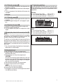
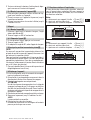
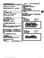
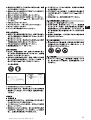
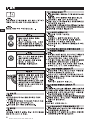
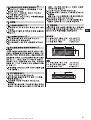
7.7 Application guidelines
For more detailed information, please ask the Hilti mar-
keting organization in your country for a copy of the Hilti
Fastening Technology Manual or the applicable national
regulations.
Concrete
A = min. distance from edge = 70 mm (2
3
/
4
″)
B = min. fastener center spacing = 80 mm (3
1
/
8
″)
C = min. base material thickness = 100 mm (4″)
Steel
A = min. distance from edge = 15 mm (
5
/
8
″)
B = min. fastener center spacing = 20 mm (
3
/
4
″)
C = min. base material thickness = 4 mm (
5
/
32
″)
BA
C
BA
ET
C
Printed: 07.07.2013 | Doc-Nr: PUB / 5069871 / 000 / 00

8
en
8. Care and maintenance
-WARNING-
Always remove the gas can and nails from the tool before
performing any work or maintenance on the tool.
8.1 Care of the tool
G Carefully remove any scraps of plastic from the nose-
piece of the tool.
G Never operate the tool if the ventilation slots are blocked.
Clean the ventilation slots carefully with a dry brush.
G Do not permit foreign objects to enter the interior of
the tool.
G Use a slightly damp cloth to clean the outside of the
tool at regular intervals.
G Do not use a spray , steam cleaning system or running
water to clean the tool.
G Always keep the grip surfaces of the tool free from oil
and grease.
G Do not use cleaning agents containing silicone.
G Do not use Hilti spray or similar lubricants.
-CAUTION-
G Do not damage the nail detector
8.2 Maintenance
Check all external parts of the tool for damage at regular
intervals and check that all operating controls function
faultlessly. Do not operate the tool when parts are dam-
aged or when operating controls do not function fault-
lessly . The tool should be repaired at a Hilti service center .
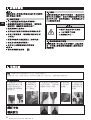
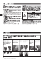
9. Troubleshooting
-CAUTION-
G The tool may get hot when in use.
G You could burn your hands.
G Allow the tool to cool.
8.3 Checking the tool after maintenance
After performing maintenance work on the tool and before
inserting the gas can, check that the sliding sleeve (safe-
ty device) is fitted and that it functions correctly (easy
sliding movement).
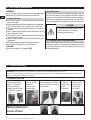
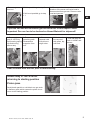
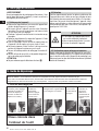
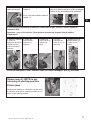
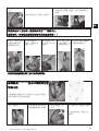
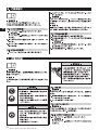
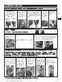
WARNING: Prior to performing any maintenance or repair on the tool, always remove the gas can.
Keep away from open flames, sparks, pilot lights, or other sources of ignition, and follow all safety instructions printed on the
gas can. Always wear suitable eye protection.
2. If sleeve
assy X-100TN
does not
return, push
reset button.
3. Check fastener guide
and magazine for debris.
Remove debris from tool
if necessary.
.
4. Check to
ensure at
least 3 nails
in the
magazine.
5. Use a new
gas can with
a new valve
head with
silver dot.
Nails jammed in
front of tool
Tool does not fire
1. Press tool against
surface and lift it up
again. Tool should
return to starting
position (sleeve assy
X-100TN moves to
front).
Printed: 07.07.2013 | Doc-Nr: PUB / 5069871 / 000 / 00

9
en
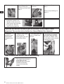
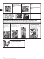
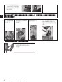
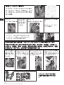
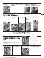
1.Remove gas can
from tool
If this is possible go to step 2
If this is not possible go to step
1.1
1.1 Press valve head toward the outside in the
direction of the arrow until valve head is
disconnected from gas can. Remove valve
head and gas can.
If you are still not able to remove gas can send tool to Hilti Repair Center.
Important: Gas can has to be declared as Hazard Material for shipment!!
2. Remove sleeve
assy X-100TN by
first pressing spring
clip and turning
sleeve assy.
3. Remove
remaining nails.
Disassemble
magazine from
tool.
4. Remove
jammed nails
with pliers or
edge cutter.
5. If nail cant
be removed
with pliers, tap
nail back. .
6. Free nail with nail
punch X-100NP and
hammer.
Clear all debris from the tool prior to reassembling.
Sleeve assy X-100TN is not
returning to starting position
Piston jams
Small plastic particle or nail debris can get stuck
in fastener guide which causes the piston to not
return to the starting position.
Printed: 07.07.2013 | Doc-Nr: PUB / 5069871 / 000 / 00

10
en
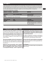
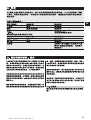
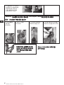
2.1 Press valve head
toward the outside in the
direction of the arrow until
valve head is disconnected
from gas can. Remove
valve head and gas can.
If you are still not able to remove gas can send tool to Hilti Repair Center.
Important: Gas can has to be declared as Hazard Material for shipment
3. Remove
remaining nails.
Disassemble
magazine from
tool
4. Remove sleeve assy
X-100TN by first
pressing spring clip and
turning sleeve assy
5. Free piston with nail
punch X-100NP and
hammer
.
6. Once piston is released,
push piston back by using
nail punch X-100NP. Clear
out any debris which may be
restricting the piston
Clear all debris from the tool prior to reassembling.
1. Push reset button If pushing reset button
does not solve the
problem go ahead with
step 2
2. Remove gas can
from tool
If this is possible go to
step 3
If this is not possible go to
step 2.1
The support leg can help to
press down the tool
perpentdicular to the base
material and thereby
improve the fastening
quality.
Printed: 07.07.2013 | Doc-Nr: PUB / 5069871 / 000 / 00

11
en
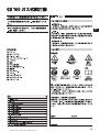
10. Disposal
Most of the materials from which Hilti tools are manufactured can be recycled. The materials must be correctly
separated before they can be recycled. In many countries, Hilti has already made arrangements for taking back
your old fastening tools for recycling. Please ask your Hilti customer service department or Hilti sales represen-
tative for further information. Please observe regional and international guidelines and regulations.
Separate the individual parts as follows:
Component / assembly Main material Recycling
Toolbox Plastic Plastics recycling
Tool casing Plastic / synthetic rubber Plastics recycling
Battery Battery recycling
(-NOTE- (observe specific national regulations)
The battery is designed to last the life of the tool.)
Electronics parts Various Electronics scrap
Screws, small parts Steel Scrap metal
Valve head Plastic Plastics recycling
Gas can Disposal of gas cans by incineration (at a
garbage incineration plant) is not permissi -
ble. Do not dispose of gas cans with other
scrap for recycling.
11. Manufacturer's warranty – tools
Hilti warrants that the tool supplied is free of defects
in material and workmanship. This warranty is valid so
long as the tool is operated and handled correctly,
cleaned and serviced properly and in accordance with
the Hilti Operating Instructions, and the technical sys-
tem is maintained. This means that only original Hilti
consumables, components and spare parts may be
used in the tool.
This warranty provides the free-of-charge repair or
replacement of defective parts only over the entire lifes-
pan of the tool. Parts requiring repair or replacement
as a result of normal wear and tear are not covered by
this warranty.
Additional claims are excluded, unless stringent
national rules prohibit such exclusion. In particular,
Hilti is not obligated for direct, indirect, incidental
or consequential damages, losses or expenses in
connection with, or by reason of, the use of, or inabil-
ity to use the tool for any purpose. Implied warranties
of merchantability or fitness for a particular purpose
are specifically excluded.
For repair or replacement, send tool or related parts
immediately upon discovery of the defect to the address
of the local Hilti marketing organization provided.
This constitutes Hilti's entire obligation with regard to
warranty and supersedes all prior or contemporane-
ous comments and oral or written agreements con-
cerning warranties.
11.1 Gas can
Observe the use-by date for the gas can (printed on the
edge of the can).
Printed: 07.07.2013 | Doc-Nr: PUB / 5069871 / 000 / 00

12
en
12. CE declaration of conformity
We declare, on our sole responsibility , that this product
complies with the following standards or standardiza-
tion documents: 75/324/EWG, 91/155/EWG, 67/548/EWG,
EN 292, EN 792-13, EN 563, EN 50081-2, EN 60529,
EN 1127-1, EN 417, EN 61000-4-3, EN 55011:1998,
EN 61000-6-2:2001, IEC 61000-6-2:1999, EN 61000-6-
3:2001, IEC 61000-6-3:1996, CISPR11:1997.
Designation: Gas-powered fastening tool
Type: GX100
Year of design: 2002
Hilti Corporation
Raimund Zaggl Dr. Walter Odoni
Senior Vice President Vice President Development
Business Area Direct Fastening Business Unit Direct Fastening
January 2003 January 2003
Printed: 07.07.2013 | Doc-Nr: PUB / 5069871 / 000 / 00

13
fr
Avant de mettre l’appareil en marche,
il est impératif de lire d’abord son mode
d’emploi.
Le présent mode d’emploi doit toujours
accompagner l’appareil.
Ne prêter ou céder l’appareil à quelqu’un
d’autre qu’en lui fournissant aussi le mode
d’emploi.
Appareil de scellement à gaz GX100
Sommaire Page
1. Consignes générales 13
2. Description 14
3. Accessoires et matières consommables 14
4. Caractéristiques techniques 15
5. Consignes de sécurité 15
6. Mise en marche 17
7. Utilisation 18
8. Nettoyage et entretien 20
9. Guide de dépannage 20
10. Recyclage 23
11. Garantie constructeur des appareils 23
12. Déclaration de conformité CE 24
Pièces de l‘appareil
햲 Poignée
햳 Bouton d'arrêt
햴 Museau de l‘appareil
햵 Douille coulissante
햶 Chargeur
햷 Plaquette signalétique
햸 Compartiment pour recharge de gaz
햹 Couvercle du compartiment à recharge de gaz
햺 Ouïes d'aération
햻 Levier de verrouillage
햽 Détente
햾 Bouton Reset
햿 Poussoir
헀 Patte d’accrochage à la ceinture
Ces chiffres renvoient aux illustrations correspondant
au texte, qui se trouvent sur les pages rabattables pré-
cédentes. Pour lire le mode d’emploi, rabattre ces pages
de manière à voir les illustrations. Dans le texte du pré-
sent mode d’emploi, le terme «appareil» désigne tou-
jours l’appareil de scellement à gaz GX 100.
Emplacement des détails d’identification sur l’appareil
La désignation du modèle et le numéro de série de votre
appareil figurent sur sa plaquette signalétique. Inscrivez
ces renseignements dans votre mode d’emploi et réfé-
rez-vous y toujours pour communiquer avec notre repré-
sentation ou votre agence Hilti.
Modèle: GX100
N° de série:
Symboles de danger
Avertissement:
danger
général!
Avertissement:
matières à risque
d’explosion!
Avertissement:
surface très
chaude!
Symboles d’obligation
Porter un
casque dur!
Porter un
casque
antibruit!
Porter des
lunettes de
protection!
Avant d’utiliser
l’appareil, lire son
mode d’emploi!
Symbole
1. Consignes générales
1.1 Mots signalant un danger et leur signification
-A VERTISSEMENT-
Le mot AVER TISSEMENT est utilisé pour attirer l’atten-
tion sur une situation potentiellement dangereuse qui
pourrait conduire à de graves blessures corporelles, voi-
re à un accident mortel.
-ATTENTION-
Le mot A TTENTION est utilisé pour attirer l’attention sur
une situation potentiellement dangereuse qui pourrait
conduire à de légères blessures corporelles ou à des
dégâts matériels.
-REMARQUE-
Le mot REMARQUE est utilisé pour donner des précisions
et des informations utiles. Ne relève pas de situations
dangereuses ou susceptibles de nuire à l’utilisateur.
1.2 Pictogrammes
Printed: 07.07.2013 | Doc-Nr: PUB / 5069871 / 000 / 00

14
fr
2. Description
L‘appareil sert à planter des clous de fabrication spécia-
le dans le béton et l’acier ainsi que dans d’autres sup-
ports destinés à un montage direct (se reporter au manuel
des techniques de fixation). Le fonctionnement de l’ap-
pareil par piston lui confère une sécurité d’emploi opti-
male et permet des fixations fiables. L’avance du piston
est assurée par un gaz.
L’appareil, la recharge de gaz, le chapeau de soupape et
les éléments de fixation constituent un ensemble où tout
se tient. Il en découle que pour travailler sans problème
avec cet appareil, l’utilisateur doit utiliser les éléments
de fixation et les recharges de gaz Hilti spécialement fabri-
qués à cet effet. Les recommandations données par Hil-
ti concernant la mise en place de ses fixations sont valables
uniquement dans ces conditions!
2.1 Principe du piston
L’énergie de la charge propulsive du gaz est transmise à
un piston dont la masse, accélérée, enfonce l’élément de
fixation dans le matériau récepteur. Comme le piston
absorbe env . 95 % de l’énergie cinétique, l’élément pénètre
à vitesse fortement réduite (inférieure à 100 m/s) dans
le matériau récepteur. L’élément est implanté lorsque le
3. Accessoires et matières consommables
Recharge de gaz avec chapeau de soupape noir GC11/GC12 standard
Recharge de gaz avec chapeau de soupape gris GC11HA/GC12HA
>1200 m (3900 ft) et/ou fréquence de percussions
élevée
Museau appareil X-100TN
Chargeur X-GM 40
Appui X-100 SL
Protection thermique X-100HP
Poinçon X-100NP
Clous Longueur Bandes à charges Pour matériau récepteur
X-EGN 14 MX 14 mm (
1
/
2
″) 10 pièces acier
X-GHP 18 MX 18 mm (
11
/
16
″) 10 pièces béton dur / béton préfabriqué / acier
X-GN 20 MX 20 mm (
3
/
4
″) 10 pièces béton / maçonnerie crépie (1 cm) /
brique silicocalcaire / maçonnerie en béton
X-GN 27 MX 27 mm (1″) 10 pièces béton / maçonnerie crépie (1 cm) /
brique silicocalcaire / maçonnerie en béton
X-GN 32 MX 32 mm (1
1
/
4
″) 10 pièces béton / maçonnerie crépie (1 cm) /
Kbrique silicocalcaire / maçonnerie en béton
X-GN 39 MX 39 mm (1
9
/
16
″) 10 pièces béton / maçonnerie crépie (1 cm) /
brique silicocalcaire / maçonnerie en béton
piston vient terminer sa course en position de butée dans
l’appareil, ce qui exclut pratiquement tout transperce-
ment dangereux du matériau récepteur , à condition, bien
sûr, que l’appareil soit correctement utilisé.
2.2 Sécurité contre les tirs intempestifs en cas de
chute
La sécurité contre les tirs intempestifs en cas de chute
résulte de l’action combinée du mécanisme de mise à
feu et de la course d’appui. Elle évite toute mise à feu
intempestive si l’appareil vient à tomber sur une surfa -
ce dure, quel que soit l’angle de chute.
2.3 Sécurité de détente
La sécurité de détente évite toute percussion lorsque seu-
le la détente est pressée. Pour qu’il y ait percussion, il
faut en plus que l’appareil prenne appui contre un sup-
port solide.
2.3.1 Sécurité d‘appui
Pour déclencher la percussion, il faut exercer une force
d’appui résolue contre le support solide.
Printed: 07.07.2013 | Doc-Nr: PUB / 5069871 / 000 / 00

4. Caractéristiques techniques
Appareil avec chargeur et recharge de gaz
Poids 3,95 kg (8,7 lbs)
Dimensions (lo × la × ha) 425×172×370 mm (16
3
/
4
″×6
3
/
4
″×14
1
/
2
″)
Longueur clous max. 39 mm (max. 1
9
/
16
″)
Diamètre clous ∅ 3,0 mm et ∅ 2,6 mm (∅ 118 et ∅ 102 in.)
Capacité chargeur 40 + 2 clous
Course d’appui env. 36 mm (1
7
/
16
″)
Force d’appui env. 120 N (27 lbs)
Température à l‘utilisation / température ambiante –5°C à 45°C (23°F à 113°F)
Fréquence max. de percussions 600 par 30 min.
1000 par h
Niveaux sonores: résultats pour 1mm de tôle sur du béton B45
1b) Niveau de puissance acoustique L
WA, 1S
109 dB (A)
Valeur d'émission au poste de travail L
pAImax
102 dB (A)
(mesurée près des oreilles de l’utilisateur)
1e) Niveau de pression acoustique sur la surface de travail L’
–
pA, 1s
96 dB (A)
(les valeurs d’émission de bruit peuvent varier selon les conditions de travail)
Recharge de gaz
Capacité 1 recharge pour 750 clous
Pour le transport et le stockage, température recommandée +5° C à +25° C (41° F à 77° F)
La recharge de gaz est sous pression.
La recharge de gaz doit rester à l’abri du soleil.
La recharge de gaz ne doit jamais être exposée à des températures supérieures à 50° C (122° F).
Gaz propulseurs Oxyde de méthyle, isobutane, propylène, propane,
butane, éthanol et isoparaffine
Recharge de gaz Le récipient de la recharge n’est plus réutilisable
Sous réserve de toutes modifications techniques!
15
fr
5. Consignes de sécurité
5.1 Consignes de sécurité fondamentales
Outre les consignes techniques de sécurité indiquées
dans les différents chapitres du présent mode d’emploi,
il a y lieu de toujours respecter strictement les directives
suivantes.
5.2 Utilisation conforme à l’usage prévu
L’appareil est destiné principalement aux utilisateurs pro-
fessionnels. Il est utilisé pour les poses à sec ainsi que
dans l‘industrie et l‘artisanat de la construction (gros-
oeuvre et second-oeuvre), plus précisément pour l’im-
plantation de clous dans le béton, l’acier, les briques sili-
cocalcaires, la maçonnerie en béton et la maçonnerie crépie.
G Toutes manipulations ou modifications sur l’appareil
sont interdites.
G Pour éviter tous risques de blessures, utiliser uni-
quement des accessoires et matières consommables
Hilti.
G Bien respecter les données concernant le fonctionne-
ment, le nettoyage et l’entretien de l’appareil qui figu-
rent dans le présent mode d’emploi.
G Ne jamais pointer l’appareil contre vous-même ou quel-
qu’un d’autre.
G Ne jamais appuyer contre la paume de votre main ou
contre une autre partie de votre corps (ni contre une
autre personne).
G Ne pas planter des clous dans des matériaux récep-
teurs qui ne conviennent pas. Par exemple:
– matériau trop dur, tel que acier soudé et acier fondu
– matériau trop mou, tel que bois et placoplâtre
– matériau trop fragile, tel que verre et carrelage
Lors de son implantation dans ce type de matériau, le
clou risque de se briser ou de le transpercer de part en
part.
Printed: 07.07.2013 | Doc-Nr: PUB / 5069871 / 000 / 00

16
fr
G L’appareil et ses accessoires peuvent être dange-
reux s’ils sont utilisés incorrectement par du person-
nel non formé ou de manière non conforme à l’usage
prévu.
G Avant d‘actionner la détente, il faut impérativement que
l’appareil prenne appui contre le support (matériau
récepteur).
G Toujours tenir l’appareil fermement et perpendiculai-
rement au matériau récepteur, ceci pour réduire le
risque de dérapage du clou sur le matériau.
G Pour éviter tout risque de rupture de clou, ne jamais
tirer un clou sur une ancienne implantation.
G Ne jamais planter de clou dans un trou existant, sauf
si Hilti le recommande.
G Respecter toujours les consignes d’utilisation.
5.3 Aménagement correcte du poste de travail
G Porter des chaussures à semelle antidérapante.
G Veillez à garder toujours une position stable et équi-
librée.
G Eviter de tenir le buste dans une position précaire.
G Ne pas exposer l’appareil aux intempéries, et pas non
plus l’utiliser dans un environnement humide ou mouillé,
et encore moins à proximité de liquides ou de gaz flam-
mables.
G Assurer un bon éclairage.
G Utiliser l'appareil uniquement dans des emplacements
bien aérés.
G Ecarter de l’environnement de travail tout objet sus-
ceptible de provoquer des lésions.
G L’appareil doit être utilisé uniquement guidé des deux
mains.
G En actionnant l’appareil, garder les bras fléchis (et non
tendus).
G Lors de l’utilisation de l‘appareil, tenir à l’écart toute
autre personne, en particulier des enfants.
G Avant de planter des clous, toujours vérifier que per -
sonne ne se trouve derrière ou dessous l’endroit où
vous travaillez.
G Toujours bien nettoyer et sécher la poignée pour enle-
ver toutes traces d’huile et de graisse.
5.4 Mesures générales de sécurité
G Utiliser l’appareil uniquement s’il est dans un état impec-
cable et seulement conformément à l’usage prévu.
G Ne jamais laisser l’appareil sans surveillance.
G Toujours décharger l’appareil (enlever la recharge de
gaz et les clous) pour le nettoyer, l’entretenir, le révi-
ser, et aussi au moment d’interrompre le travail.
G Lorsque l’appareil n’est pas utilisé, toujours en retirer
la recharge de gaz et le ranger à part dans un endroit
sec, en hauteur ou fermé à clé, hors de portée des
enfants.
G Avant de transporter l’appareil, en retirer la recharge
de gaz.
G Ne pas utiliser l’appareil lorsque l’un de ses compo-
sants est endommagé ou hors d’usage.
5.4.1 Dangers mécaniques
G Utiliser uniquement les clous homologués pour l’ap-
pareil.
G Ne pas emplir de clous le chargeur sans que celui-ci
soit correctement monté dans l’appareil. Autrement
les clous risquent d’être propulsés hors de l’appareil.
5.4.2 Dangers thermiques
G Laisser l’appareil se refroidir lorsqu’il est trop chaud.
G Ne pas dépasser la fréquence maximale des tirs (nombre
de tirs par unité de temps). Autrement, l’appareil risque
une surchauffe.
5.4.3 Les gaz
-A VERTISSEMENT-
Gaz à l’état liquide sous pression.
Lire attentivement la mise en garde contre les dangers
et les premiers secours sur la recharge de gaz.
Du fait de sa teneur en oxyde de méthyle, isobutane, pro-
pylène, propane, butane, éthanol et isoparaffine, le gaz
s’enflamme très facilement.
Une fois vide, la recharge de gaz ne peut être rechargée.
G Ne pas utiliser de recharges de gaz endommagées.
G Ne pas essayer d’ouvrir une recharge de gaz.
G Ne jamais diriger un jet de gaz sur une personne, un
animal ou une plante.
G Tenir le gaz à l’écart de toute source d'inflammation
telle que feu, étincelles, veilleuse d’allumage, décharges
statiques et surfaces rayonnant une forte chaleur.
G Ne pas fumer durant le travail avec l’appareil.
G Ne pas tenter d’ouvrir par la force la recharge de gaz,
ni de la brûler, de l’aplatir ou de la récupérer pour un
quelconque autre usage.
Stockage
G Ne stocker aucune recharge de gaz dans une pièce habi-
tée ou dans un local donnant accès à une pièce habitée.
G Conserver les recharges de gaz uniquement dans des
emplacements bien aérés et au sec.
G Garder la recharge de gaz hors de la portée d’enfants.
G Les recharges de gaz doivent se trouver à l’abri du soleil
et ne doivent pas être exposées à des températures
supérieures à 50°C (122°F).
G Pour le stockage, la température recommandée est de
5°C à 25°C (41°F à 77°F).
Printed: 07.07.2013 | Doc-Nr: PUB / 5069871 / 000 / 00
La page est en cours de chargement...
La page est en cours de chargement...
La page est en cours de chargement...
La page est en cours de chargement...
La page est en cours de chargement...
La page est en cours de chargement...
La page est en cours de chargement...
La page est en cours de chargement...
La page est en cours de chargement...
La page est en cours de chargement...
La page est en cours de chargement...
La page est en cours de chargement...
La page est en cours de chargement...
La page est en cours de chargement...
La page est en cours de chargement...
La page est en cours de chargement...
La page est en cours de chargement...
La page est en cours de chargement...
La page est en cours de chargement...
La page est en cours de chargement...
La page est en cours de chargement...
La page est en cours de chargement...
La page est en cours de chargement...
La page est en cours de chargement...
La page est en cours de chargement...
La page est en cours de chargement...
La page est en cours de chargement...
La page est en cours de chargement...
La page est en cours de chargement...
La page est en cours de chargement...
La page est en cours de chargement...
La page est en cours de chargement...
La page est en cours de chargement...
La page est en cours de chargement...
La page est en cours de chargement...
La page est en cours de chargement...
La page est en cours de chargement...
La page est en cours de chargement...
La page est en cours de chargement...
La page est en cours de chargement...
La page est en cours de chargement...
La page est en cours de chargement...
La page est en cours de chargement...
La page est en cours de chargement...
La page est en cours de chargement...
La page est en cours de chargement...
La page est en cours de chargement...
La page est en cours de chargement...
La page est en cours de chargement...
-
 1
1
-
 2
2
-
 3
3
-
 4
4
-
 5
5
-
 6
6
-
 7
7
-
 8
8
-
 9
9
-
 10
10
-
 11
11
-
 12
12
-
 13
13
-
 14
14
-
 15
15
-
 16
16
-
 17
17
-
 18
18
-
 19
19
-
 20
20
-
 21
21
-
 22
22
-
 23
23
-
 24
24
-
 25
25
-
 26
26
-
 27
27
-
 28
28
-
 29
29
-
 30
30
-
 31
31
-
 32
32
-
 33
33
-
 34
34
-
 35
35
-
 36
36
-
 37
37
-
 38
38
-
 39
39
-
 40
40
-
 41
41
-
 42
42
-
 43
43
-
 44
44
-
 45
45
-
 46
46
-
 47
47
-
 48
48
-
 49
49
-
 50
50
-
 51
51
-
 52
52
-
 53
53
-
 54
54
-
 55
55
-
 56
56
-
 57
57
-
 58
58
-
 59
59
-
 60
60
-
 61
61
-
 62
62
-
 63
63
-
 64
64
-
 65
65
-
 66
66
-
 67
67
-
 68
68
-
 69
69


Hilti GX 100 Mode d'emploi
- Catégorie
- Outils électroportatifs
- Taper
- Mode d'emploi
dans d''autres langues
- English: Hilti GX 100 Operating instructions