Valor 2530CIK Le manuel du propriétaire
- Catégorie
- Cheminées
- Taper
- Le manuel du propriétaire

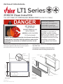
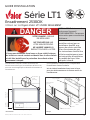
HOT GLASS WILL
CAUSE BURNS.
DO NOT TOUCH GLASS
UNTIL COOLED.
NEVER ALLOW CHILDREN
TO TOUCH GLASS.
DANGER
!
A barrier designed to reduce the risk of burns from the hot
viewing glass is provided with this appliance and must be
installed for the protection of children and other at-risk
individuals.
The 2530 Clean Installation Kit installs at the time of
framing the appliance. Wall fi nishes are then applied
and butted directly up to the outer frame.
Depth
1-1/4”
[31.75 mm]
20-13/16”
[530 mm]
41” [1042 mm]
7-15/16”
[201 mm]
Left hand
door
Cover
plate
2500K engine
Note: This kit must be
installed or serviced by a
qualified installer, service
agency or gas supplier. These
instructions are to be used
in conjunction with the main
installation instructions
for the above listed heater
model.
INSTALLER: Leave this
manual with the appliance.
CONSUMER: Retain this
manual for future reference.
This kit is not intended to and cannot be installed with
any other trim.
See appliance installation manual for more
information about finishing around this kit.
Right
hand door
CIK assembly
Barrier
screen
OverviewDimensions
2530CIK Clean Install Kit
Use with Valor LT1 2500 Heater Models ONLY (series K or later)
INSTALLATION MANUAL
LT1 Series
4009376-03
©2023, Miles Industries Ltd.

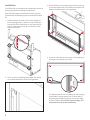
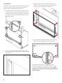
Installation
The 2530CIK kit is intended to be installed at the time of
framing, and before installing the wall fi nish.
With the 2500 engine installed and in place, you can
proceed with the following steps to install the 2530CIK
kit.
1. Break off tabs from each corner of the fi replace’s
front opening (8 tabs, 2 at each corner). Bend tabs
back and forth to break them, or cut them with tin
snips. (These tabs are only for use with kits other
than the 2530CIK)
2. File or trim any remaining sharp edges. Be careful
not to allow material to fall into the appliance.
3. Slide CIK frame into the opening as shown, pushing
it until the screw holes in the frame line up with the
deepest available holes in the appliance.
4. Screw the CIK frame to the interior of the opening in
the aligned screw holes (4 screws).
The fi replace and kit are now ready for wall fi nishing
to take place. Cement board, tile, or other wall fi n-
ishes may be completed right up to the outer edge
of the CIK frame. Do not fi nish past this edge, as it
will prevent barrier screen installation.
2

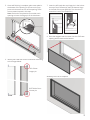
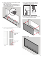
5. Once wall fi nishing is complete, place cover plate in
the bottom of the opening. It will rest on the sup-
ports at the bottom corners of the opening. There
are no screws inserted in this step.
Note: Each end of the plate has a rounded notch
opening to insert the hinge pin of the side doors.
6. Identify left hand door and its orientation according
to the images below.
Cover plate
Notch in
cover plate
Front Rear
TOP of door:
Longer pin
BOTTOM of door:
Shorter pin
7. Insert the left hand door top hinge pin in the hole at
the top of the CIK frame (a), then the bottom hinge
in the hole of the cover panel (b). Turn the door in
toward the back of the fi replace (c).
8. Repeat for right hand door.
9. Place the magnetic barrier screen into the CIK frame
opening with the tabs at the bottom.
Assembly of the kit is complete.
Top pin
Bottom pin
a
bc
3

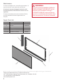
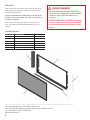
Code Description Part Number
1CIK assembly 4008316AZ
2 Left door 4008322AZ
3Right door 4008324AZ
4 Cover plate 4008839AZ
5 Barrier screen 4008320
not shown #8 x 3/8 s/t screws (4) 4000661
Repair Parts List
Designed and Manufactured by / for Miles Industries Ltd.
190 – 2255 Dollarton Highway, North Vancouver, B.C., CANADA V7H 3B1
Tel. 604-984-3496 Fax 604-984-0246
www.valorfi replaces.com
Because our policy is one of constant development and improvement, details may vary slightly from those given in this publication.
Maintenance
To clean the fi replace trim, use mild soap and water. To
clean the barrier screen, dust with a soft brush.
If the barrier becomes damaged, the barrier shall
be replaced with the manufacturer’s barrier for this
appliance.
To clean the window and ceramics inside the fi rebox,
see the Homeowner’s Manual supplied with the
fi replace.
WARNING
DO NOT TOUCH THE BARRIER SCREEN OR
FIREPLACE WHILE THEY ARE HOT! Let the
fi replace cool fi rst before cleaning it.
FOR SAFETY PURPOSE, ensure the barrier
screen is re-installed on the fi replace front
after maintenance if it has been removed.
1
2
3
4
5
4

L’Encadrement 2530CIK s’installe au moment de
l’encastre-ment du foyer. Les matériaux de fi nition du
mur sont ensuite appliqués et abouttés directement à
l’encadrement.
Encadrement 2530CIK
Utilisez sur les foyers Valor LT1 2500K SEULEMENT
GUIDE D’INSTALLATION
Série LT1
Note : Ce kit doit être
installé ou réparé par un
installateur qualifié, une
agence de service certifiée
ou un fournisseur de gaz.
Ces instructions doivent être
utilisées conjointement avec
les instructions d’installation
du modèle de foyer Valor
indiqué ci-dessus.
VITRE CHAUDE - RISQUE
DE BRÛLURES.
NE TOUCHEZ PAS UNE
VITRE NON REFROIDIE.
NE LAISSEZ JAMAIS UN
ENFANT TOUCHER LA VITRE.
L’écran pare-étincelles fourni avec ce foyer réduit le risque
de brûlure en cas de contact accidentel avec la vitre chaude
et doit être installé pour la protection des enfants et des
personnes à risques.
DANGER
!INSTALLATEUR : Laissez cette
notice avec l’appareil.
CONSOMMATEUR : Conservez
cette notice pour consultation
ultérieure.
Cet encadrement n’est pas conçu et ne peut être
l’installé avec d’autres bordures.
Voir le Guide d’installation fourni avec le foyer
pour plus d’information sur la finition autour de
l’encadrement.
Profondeur
1-1/4”
[32 mm]
20-13/16”
[530 mm]
41” [1042 mm]
7-15/16”
[201 mm]
Porte latérale
gauche
Couvercle
Foyer 2500K
Porte latérale
droite
Cadre
Pare-étincelles
ConceptDimensions
©2023, Miles Industries Ltd. Tous droits réservés. 5

Installation
Le 2530CIK est conçu pour être installé avant la fi nition
du mur. Une fois les pièces intérieures du foyer en
place, installez l’encadrement comme suit :
1. À chaque coin de l’ouverture de la caisse du foyer
coupez les pièces de métal formant les coins; ils ne
sont pas utilisés pour cet encadrement. Les pièces
se brisent en les pliant et dépliant mais aussi avec
un ciseau à métal.
2. Limez ou coupez les bords coupants. Faites atten-
tion de ne pas laisser tomber de morceau de métal
dans l’appareil.
3. Insérez le cadre dans l’ouverture et poussez-le
jusqu’à ce que ses trous de fi xation soient alignés
aux trous de montage les plus profonds.
4. Fixez le cadre au montant intérieur de l’ouverture
utilisant les trous alignés selon l’étape 3 (4 vis).
Les matériaux de fi nition du mur peuvent être
maintenant appliqués. Le panneau de béton, la tuile
ou autre fi ni peuvent être aboutés au cadre. Ne pas
empiéter sur l’ouverture afin de pouvoir installer le
pare-étincelles.
6

5. Posez le couvercle en bas sur les supports latéraux
à chaque coin du cadre.
Note : L’encoche arrondie à chaque extrémité du
couvercle doit être aligné avec le trou qui servira à
tenir la porte latérale en place. .
6. Identifi ez la porte latérale gauche et son orientation
selon les images ci-dessous.
Couvercle
Encoche
alignée
Avant Arrière
HAUT de la porte :
Cheville plus
longue
BAS de la porte :
Cheville plus
courte
7. Placez la porte latérale en insérant d’abord sa
cheville du haut (a) puis sa cheville du bas (b).
Tournez la porte vers l’arrière (c).
8. Répétez pour la porte latérale droite.
9. Fixez le pare-étincelles aimanté, les onglets vers le
bas, à la bordure à l’intérieur du cadre.
Cheville du
haut
Cheville du bas
a
bc
Encadrement installé
7

Code Description No de pièce
1Cadre 4008316AZ
2 Porte latérale gauche 4008322AZ
3 Porte latérale droite 4008324AZ
4Couvercle 4008839AZ
5Pare-étincelles 4008320
non montré Vis #8 x 3/8 (4) 4000661
Liste de pièces
Entretien
Pour nettoyer le cadre de métal, utilisez de l’eau et un
savon doux. Pour nettoyer le pare-étincelles, utilisez
une brosse à poils doux.
Si le pare-étincelles est endommagé, il doit être rem-
placé par le pare-étincelles conçu par le manufacturi-
er pour cet appareil.
Pour nettoyer la vitre de la fenêtre et l’intérieur du
foyer, consultez le Guide du propriétaire fourni avec
le foyer.
1
2
3
4
5
AVERTISSEMENT
NE TOUCHEZ PAS AU PARE-ÉTINCELLES
OU AU FOYER LORSQU’ILS SONT CHAUDS!
Laissez le foyer refroidir avant de le
nettoyer.
POUR DES RAISONS DE SÉCURITÉ, assurez-
vous que le pare-étincelles soit réinstallé
sur la bordure après l’entretien s’il a été
enlevé.
Conçue et fabriquée par / pour Miles Industries Ltd.
190 – 2255 Dollarton Highway, North Vancouver, BC, CANADA V7H 3B1
Tél. 604-984-3496 Téléc. 604-984-0246
www.foyervalor.com
Parce que nous favorisons une politique de développement continu, certains détails de la présente publication peuvent varier.
8
-
 1
1
-
 2
2
-
 3
3
-
 4
4
-
 5
5
-
 6
6
-
 7
7
-
 8
8


Valor 2530CIK Le manuel du propriétaire
- Catégorie
- Cheminées
- Taper
- Le manuel du propriétaire
dans d''autres langues
- English: Valor 2530CIK Owner's manual
Documents connexes
-
Valor 2575LFB Le manuel du propriétaire
-
-
-
-
-
-
-
-
-