tekmar A-T-294 Smart Boiler Control Manuel utilisateur
- Taper
- Manuel utilisateur

Application Brochure
Smart Boiler Control 294
A-T-294
WARNING
!
Please read carefully before proceeding with
installation. Your failure to follow any attached
instructions or operating parameters may lead to the
product’s failure.
Keep this Manual for future reference.
Central Heating With Up to Four Non-condensing Boilers ......................................................2
Central Heating and Side-Arm DHW With Up to Four Condensing Boilers ..........................................4
Central, DHW and Setpoint Heating With Two Condensing, Two Non-condensing Hybrid Boiler Plant.....................6
Central, DHW and Setpoint Heating With Up to Eight Condensing Boilers ..........................................8
Central and DHW Heating With Up to Four Condensing Boilers Using Variable Primary Flow Piping .....................12
Volume DHW Heating With Up to Four Water Heaters ........................................................14
Application Page

2A-T-294 2205 © 2022 tekmar
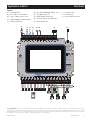
Description
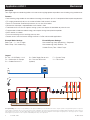
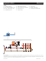
Four single-stage non-condensing boilers with reverse-return piping operate to provide a central heating using outdoor reset.
Concept Drawing: This is only a concept drawing, not an engineered drawing. It is not intended to describe a complete system, nor any particular system. It is up to the
system designer to determine the necessary components for and configuration of the particular system being designed, including additional equipment, isolation relays (for
loads greater than the control’s specified output ratings), and any safety devices which in the judgement of the designer are appropriate, in order to properly size, configure
and design that system and to ensure compliance with building and safety code requirements.
Features:
• Central heating using outdoor air reset reduces the energy consumption up to 30% compared to fixed setpoint temperatures.
• PID staging automatically adjusts the number of boilers fired to match the load.
• Equal run time rotation automatically balances the run time of the boilers.
• Combustion air damper is opened before the first boiler is fired.
• Fixed lead with first on/first off supports venting systems that require the lead boiler to prime the vent.
• Programmable schedule to reduce energy consumption during unoccupied time periods.
• Warm weather shut down.
• Pressure monitoring with low and high pressure alert.
• Remote access from the Internet through the Watts® OnSite web or mobile applications.
Essential Boiler Settings:
Boiler Type = 1, 2, 3 or 4 stages
Boiler Group = Non-condensing
B1...B4 = On/Off Boilers 1 to 4
D1 = Combustion Air Damper
S1 = Outdoor Sensor 070
S2 = Boiler Supply Sensor 082
S3 = Pressure Sensor 088
(Optional)
P1 = System Pump
V1 = Zone Valves
Legend
Essential System Settings:
Non-condensing Group Sequencing = Sequential
Non-condensing Group Rotation = On
Variable Primary Flow = Boiler Pumps
S3 P1
V1
S2
D1
B1B2B3B4
S1
294
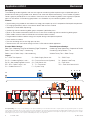
Application A 294-1 Mechanical

A-T-294 2205 © 2022 tekmar 3
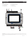
Concept Drawing: This is only a concept drawing, not an engineered drawing. It is not intended to describe a complete system, nor any particular system. It is up to the
system designer to determine the necessary components for and configuration of the particular system being designed, including additional equipment, isolation relays (for
loads greater than the control’s specified output ratings), and any safety devices which in the judgement of the designer are appropriate, in order to properly size, configure
and design that system and to ensure compliance with building and safety code requirements.
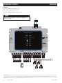
B1...B4 = On/Off Boilers 1 to 4
D1 = Combustion Air Damper
E1 = Ethernet (Optional)
S1 = Outdoor Sensor 070
S2 = Boiler Supply Sensor 082
S3 = Pressure Sensor 088 (Optional)
P1 = System Pump
V1 = Zone Valve End Switch
Legend
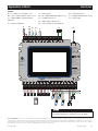
FCC ID: 2AHQR-11500A
Contains FCC ID:
2AC7Z-ESP32WROOM32E
QOQMGM12P0
Contains IC ID:
21098-ESPWROOM32E
5123A-MGM12P0
CAN ICES-3 (A)/NMB-3(A)
Class 2 Circuits
Boiler Mod:
Class 2 Circuits
Input Power:
115 V (ac) ±10%, 60 Hz, 9 W
Relays:
230 V (ac), 5 A, 1/3 hp
Calls:
24 V (ac) or Short
Operating Temperature:
32°F to 122°F (0°C to 50°C)
Use Copper Conductors Only
2827
Boiler 2
2625
Boiler 1
24
Ethernet
3029
Boiler 3
3231
Boiler 4
3433
Boiler 1
Enable
3635
Boiler 2
Enable
3837
Boiler 3
Enable
4039
Boiler 4
Enable
4241
Boiler 1
Pump/Vlv
4443
Boiler 2
Pump/Vlv
4645
Boiler 3
Pump/Vlv
4847
Boiler 4
Pump/Vlv
50
49
Comb
Air Relay
5251
System
Pump
5453
DHW
Pump
5655
Power
N
DANGER
DANGER
To Reduce the Risk of Electric
Shock - Do not connect to a
circuit operating at more than
150 volts to ground.
Pour réduire les risques
d'électrocution choc - ne pas
raccorder à un circuit
fonctionnant à plus de 150 V à
la terre.
L
54
Out Sens
76
Boiler
Sensor
98
DHW
Sensor
1110
Heat
1312
DHW
1514
Setpoint
1716
tN4
Boiler Bus
19 2018
+Gnd
Expansion
22 2321
ACB+Gnd
Boiler Modbus
231
Ref In Gnd
Pressure Sens
Mod
+Mod
+Mod
+Mod
+
Call
+Call
+Call
+
EMS
+
H2061B Smart Boiler Control 294
For product literature:
Pour la documentation
du produit:
Watts.com/tekmar
tektra 1150-01
Designed and assembled
in Canada
N
G
L
LNG
LNG
TT TT TT TT
S3
P1
D1
B1 B2 B3 B4
S2 V1 E1
S1
Application A 294-1 Electrical

4A-T-294 2205 © 2022 tekmar
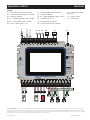
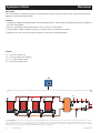
Description
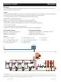
Four modulating condensing boilers operate to provide central heating using outdoor reset, and domestic hot water tank
heating using side-arm piping to boiler 1.
Concept Drawing: This is only a concept drawing, not an engineered drawing. It is not intended to describe a complete system, nor any particular system. It is up to the
system designer to determine the necessary components for and configuration of the particular system being designed, including additional equipment, isolation relays (for
loads greater than the control’s specified output ratings), and any safety devices which in the judgement of the designer are appropriate, in order to properly size, configure
and design that system and to ensure compliance with building and safety code requirements.
Features:
• Central heating using outdoor air reset reduces the energy consumption up to 30% compared to fixed setpoint temperatures.
• Simultaneous central heating and domestic hot water heating using the DHW side-arm piping.
• PID staging automatically adjusts the number of boilers fired to match the load.
• Sequential or Parallel boiler sequencing.
• Equal run time rotation automatically balances the run time of the boilers.
• Boiler modbus communication to read lockout or hold error codes on boilers.
• Programmable schedule to reduce energy consumption during unoccupied time periods.
• Warm weather shut down.
• Pressure monitoring with low and high pressure alert.
• Remote access from the Internet through the Watts OnSite web or mobile applications.
Essential Boiler Settings:
Boiler Type = Modulating Firing Rate or
Modulating Target Temperature
Boiler Group = Condensing
A1 = DHW Tank Aquastat
B1...B4 = Modulating Boilers 1 to 4
BP1...BP4 = Boiler Pumps 1 to 4
S1 = Outdoor Sensor 070
S2 = Boiler Supply Sensor 082
S3 = Pressure Sensor 088 (Optional)
S4 = DHW Sensor 082
P1 = System Pump
P2 = DHW Pump
V1 = Zone Valves
Legend
Essential System Settings:
Condensing Group Sequencing = Sequential or Parallel
Condensing Group Rotation = On
Variable Primary Flow = Boiler Pumps
P1S2 S3
V1
A1
S4
P2
B1B2B3B4
S1
BP1BP2BP3BP4
294
Application A 294-2 Mechanical

A-T-294 2205 © 2022 tekmar 5
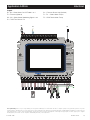
FCC ID: 2AHQR-11500A
Contains FCC ID:
2AC7Z-ESP32WROOM32E
QOQMGM12P0
Contains IC ID:
21098-ESPWROOM32E
5123A-MGM12P0
CAN ICES-3 (A)/NMB-3(A)
Class 2 Circuits
Boiler Mod:
Class 2 Circuits
Input Power:
115 V (ac) ±10%, 60 Hz, 9 W
Relays:
230 V (ac), 5 A, 1/3 hp
Calls:
24 V (ac) or Short
Operating Temperature:
32°F to 122°F (0°C to 50°C)
Use Copper Conductors Only
2827
Boiler 2
2625
Boiler 1
24
Ethernet
3029
Boiler 3
3231
Boiler 4
3433
Boiler 1
Enable
3635
Boiler 2
Enable
3837
Boiler 3
Enable
4039
Boiler 4
Enable
4241
Boiler 1
Pump/Vlv
4443
Boiler 2
Pump/Vlv
4645
Boiler 3
Pump/Vlv
4847
Boiler 4
Pump/Vlv
50
49
Comb
Air Relay
5251
System
Pump
5453
DHW
Pump
5655
Power
N
DANGER
DANGER
To Reduce the Risk of Electric
Shock - Do not connect to a
circuit operating at more than
150 volts to ground.
Pour réduire les risques
d'électrocution choc - ne pas
raccorder à un circuit
fonctionnant à plus de 150 V à
la terre.
L
54
Out Sens
76
Boiler
Sensor
98
DHW
Sensor
1110
Heat
1312
DHW
1514
Setpoint
1716
tN4
Boiler Bus
19 2018
+Gnd
Expansion
22 2321
ACB+Gnd
Boiler Modbus
231
Ref In Gnd
Pressure Sens
Mod
+Mod
+Mod
+Mod
+
Call
+Call
+Call
+
EMS
+
H2061B Smart Boiler Control 294
For product literature:
Pour la documentation
du produit:
Watts.com/tekmar
tektra 1150-01
Designed and assembled
in Canada
N
G
L
LNG LNG
LNG LNG
LNG
LNG
-+Gnd
+-+-+-+-TT TT TT TT
Concept Drawing: This is only a concept drawing, not an engineered drawing. It is not intended to describe a complete system, nor any particular system. It is up to the
system designer to determine the necessary components for and configuration of the particular system being designed, including additional equipment, isolation relays (for
loads greater than the control’s specified output ratings), and any safety devices which in the judgement of the designer are appropriate, in order to properly size, configure
and design that system and to ensure compliance with building and safety code requirements.
P1
S2
S3 V1 A1 C1
S4 E1
P2
B1M1 M2 M3 M4 B2 B3 B4
S1
BP1
BP2
BP3
BP4
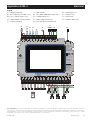
A1 = DHW Aquastat
B1...B4 = Boilers 1 to 4 Enable
BP1...BP4 = Boiler Pumps 1 to 4
C1 = Boiler Modbus Communication
E1 = Ethernet (Optional)
Legend
Application A 294-2 Electrical
M1...M4 = Boiler Modulation Signals 1 to 4
S1 = Outdoor Sensor 070
S2 = Boiler Supply Sensor 082
S3 = Pressure Sensor 088 (Optional)
S4 = DHW Sensor 082
P1 = System Pump
P2 = DHW Pump
V1 = Zone Valve End Switch

6A-T-294 2205 © 2022 tekmar
Description
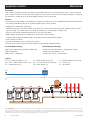
Two modulating condensing boilers and two one-stage non-condensing boilers operate create a hybrid boiler plant to
provide central heating using outdoor reset, domestic hot water and setpoint load heating. The two condensing boilers
create a group to provide equal run time rotation. Likewise the two non-condensing boilers create a group that provide
equal run time rotation. All condensing group boilers must fire before any non-condensing boilers are fired.
Concept Drawing: This is only a concept drawing, not an engineered drawing. It is not intended to describe a complete system, nor any particular system. It is up to the
system designer to determine the necessary components for and configuration of the particular system being designed, including additional equipment, isolation relays (for
loads greater than the control’s specified output ratings), and any safety devices which in the judgement of the designer are appropriate, in order to properly size, configure
and design that system and to ensure compliance with building and safety code requirements.
A1 = DHW Tank Aquastat
B1, B2 = Condensing Boiler 1 and 2
B3, B4 = Non-condensing Boiler 3 and 4
BP1...BP4 = Boiler Pumps 1 to 4
S1 = Outdoor Sensor 070
S2 = Boiler Supply Sensor 082
S3 = Pressure Sensor 088 (Optional)
S4 = DHW Sensor 082
T1...T4 = Thermostats
P1 = System Pump
P2 = DHW Pump
P3 = Setpoint Load Pump
V1 = Zone Valves
ZVC = Zone Valve Control 304V
Legend
Essential Boiler Settings:
Boiler Type = Modulating Firing Rate or Modulating Target Temperature
Boilers 1 and 2: Boiler Group = Condensing
Boilers 3 and 4: Boiler Group = Non-condensing
Essential System Settings:
Condensing Group Sequencing = Sequential or Parallel
Condensing Group Rotation = On
Variable Primary Flow = Boiler Pumps
B1B2B3B4
BP1
BP2BP3BP4
P1
S2 S3
V1
T1 T2 T3 T4
S1
A1
P2
P3
294
ZVC
Features:
• Central heating using outdoor air reset reduces the energy consumption up to 30% compared to fixed setpoint temperatures.
• PID staging automatically adjusts the number of boilers fired to match the load.
• Sequential or Parallel boiler sequencing.
• Condensing and non-condensing boiler groups to operate hybrid boiler plants.
• Equal run time rotation automatically balances the run time of the condensing and non-condensing boiler groups.
• Boiler modbus communication to read lockout or hold error codes on boilers.
• Programmable schedule to reduce energy consumption during unoccupied time periods.
• Warm weather shut down.
• Pressure monitoring with low and high pressure alert.
• Remote access from the Internet through the Watts OnSite web or mobile applications.
Application A 294-3 Mechanical

A-T-294 2205 © 2022 tekmar 7
Concept Drawing: This is only a concept drawing, not an engineered drawing. It is not intended to describe a complete system, nor any particular system. It is up to the
system designer to determine the necessary components for and configuration of the particular system being designed, including additional equipment, isolation relays (for
loads greater than the control’s specified output ratings), and any safety devices which in the judgement of the designer are appropriate, in order to properly size, configure
and design that system and to ensure compliance with building and safety code requirements.
Essential System Settings:
Condensing Group Sequencing = Sequential or Parallel
Condensing Group Rotation = On
Variable Primary Flow = Boiler Pumps
FCC ID: 2AHQR-11500A
Contains FCC ID:
2AC7Z-ESP32WROOM32E
QOQMGM12P0
Contains IC ID:
21098-ESPWROOM32E
5123A-MGM12P0
CAN ICES-3 (A)/NMB-3(A)
Class 2 Circuits
Boiler Mod:
Class 2 Circuits
Input Power:
115 V (ac) ±10%, 60 Hz, 9 W
Relays:
230 V (ac), 5 A, 1/3 hp
Calls:
24 V (ac) or Short
Operating Temperature:
32°F to 122°F (0°C to 50°C)
Use Copper Conductors Only
2827
Boiler 2
2625
Boiler 1
24
Ethernet
3029
Boiler 3
3231
Boiler 4
3433
Boiler 1
Enable
3635
Boiler 2
Enable
3837
Boiler 3
Enable
4039
Boiler 4
Enable
4241
Boiler 1
Pump/Vlv
4443
Boiler 2
Pump/Vlv
4645
Boiler 3
Pump/Vlv
4847
Boiler 4
Pump/Vlv
50
49
Comb
Air Relay
5251
System
Pump
5453
DHW
Pump
5655
Power
N
DANGER
DANGER
To Reduce the Risk of Electric
Shock - Do not connect to a
circuit operating at more than
150 volts to ground.
Pour réduire les risques
d'électrocution choc - ne pas
raccorder à un circuit
fonctionnant à plus de 150 V à
la terre.
L
54
Out Sens
76
Boiler
Sensor
98
DHW
Sensor
1110
Heat
1312
DHW
1514
Setpoint
1716
tN4
Boiler Bus
19 2018
+Gnd
Expansion
22 2321
ACB+Gnd
Boiler Modbus
231
Ref In Gnd
Pressure Sens
Mod
+Mod
+Mod
+Mod
+
Call
+Call
+Call
+
EMS
+
H2061B Smart Boiler Control 294
For product literature:
Pour la documentation
du produit:
Watts.com/tekmar
tektra 1150-01
Designed and assembled
in Canada
N
G
L
LNG LNG
LNG LNG
LNG
LNG
tN4 C -+Gnd
+-+-TT TT TT TT
A1 = Zone Valve Control DHW Terminals
A2 = Zone Valve Control Boiler XX Terminals
A3 = Setpoint Load Call
B1, B2 = Modulating Boiler 1 and 2 Enable
B3, B4 = On-Off Boiler 3 and 4 Enable
BP1...BP4 = Boiler Pumps 1 to 4
Legend
P1
S2
S3 A2 A3
A1 C1 E1
P2
B1M1 M2 B2 B3 B4
S1
BP1
BP2
tN4
BP3
BP4
Application A 294-3 Electrical
C1 = Boiler Modbus Communication
E1 = Ethernet (Optional)
M1, M2 = Boiler Modulation Signal 1 and 2
S1 = Outdoor Sensor 070
S2 = Boiler Supply Sensor 082
S3 = Pressure Sensor 088 (Optional)
tN4 = Zone Valve Control
tN4 and C
P1 = System Pump
P2 = DHW Pump

8A-T-294 2205 © 2022 tekmar
Description
Eight modulating condensing boilers are operated to provide central heating using outdoor reset, domestic hot water tank
and setpoint load heating. The domestic hot water tank is located on the system loop.
Concept Drawing: This is only a concept drawing, not an engineered drawing. It is not intended to describe a complete system, nor any particular system. It is up to the
system designer to determine the necessary components for and configuration of the particular system being designed, including additional equipment, isolation relays (for
loads greater than the control’s specified output ratings), and any safety devices which in the judgement of the designer are appropriate, in order to properly size, configure
and design that system and to ensure compliance with building and safety code requirements.
Features:
• Central heating using outdoor air reset reduces the energy consumption up to 30% compared to fixed setpoint temperatures.
• PID staging automatically adjusts the number of boilers fired to match the load.
• Sequential or Parallel boiler sequencing.
• Sequencing of up to 8 boilers using Smart Boiler Expansion 294EXP (up to 16 boilers possible using three 294EXP).
• Equal run time rotation automatically balances the run time of the boilers.
• Boiler modbus communication to read lockout or hold error codes on boilers.
• Programmable schedule to reduce energy consumption during unoccupied time periods.
• Warm weather shut down.
• Pressure monitoring with low and high pressure alert.
• Remote access from the Internet through the Watts OnSite web or mobile applications.
BP1
294EXP
B1B2B3B4B5B6B7B8
BP2BP3BP4BP5BP6BP7BP8
Application A 294-4 Mechanical

A-T-294 2205 © 2022 tekmar 9
Concept Drawing: This is only a concept drawing, not an engineered drawing. It is not intended to describe a complete system, nor any particular system. It is up to the
system designer to determine the necessary components for and configuration of the particular system being designed, including additional equipment, isolation relays (for
loads greater than the control’s specified output ratings), and any safety devices which in the judgement of the designer are appropriate, in order to properly size, configure
and design that system and to ensure compliance with building and safety code requirements.
A1 = Setpoint Load Call
B1...B8 = Modulating Boilers 1 to 8
BP1...BP8 = Boiler Pumps 1 to 8
S1 = Outdoor Sensor 070
Legend
294 S1
V1
S2 S3 P1
P2
P3
S4 A1
Application A 294-4 Mechanical
S2 = Boiler Supply Sensor 082
S3 = Pressure Sensor 088 (Optional)
S4 = DHW Sensor 078
P1 = System Pump
P2 = DHW Pump
P3 = Setpoint Load Pump
V1 = Thermostatic Radiator Valves

10 A-T-294 2205 © 2022 tekmar
B5M5 M6 M7 M8 B6 B7 B8
BP5
BP6
BP7
BP8
To 294
B5...B8 = Boiler On-Off Enable 5 to 8
BP5...BP48 = Boiler Pumps 5 to 8
M5...M8 = Boiler Modulation Signal 5 to 8
Legend
CAN ICES-3 (A)/NMB-3(A)
Class 2 Circuits
Boiler Mod:
Class 2 Circuits
Input Power:
115 V (ac) ±10%, 60 Hz, 6 W
Relays:
230 V (ac), 5 A, 1/3 hp
Operating Temperature:
32°F to 122°F (0°C to 50°C)
Use Copper Conductors Only
H2062B
76
Boiler 6
54
Boiler 5
Mod
98
Boiler 7
1110
Boiler 8
1312
Boiler 5
Enable
1514
Boiler 6
Enable
1716
Boiler 7
Enable
1918
Boiler 8
Enable
2120
Boiler 5
Pump/Vlv
2322
Boiler 6
Pump/Vlv
2524
Boiler 7
Pump/Vlv
2726
Boiler 8
Pump/Vlv
2928
Power
N
To Reduce the Risk of Electric
Shock - Do not connect to a
circuit operating at more than
150 volts to ground.
Pour réduire les risques
d'électrocution choc - ne pas
raccorder à un circuit
fonctionnant à plus de 150 V à
la terre.
L
231
+Gnd
Expansion
Expansion 5 to 8
Set switches: 1 to Off, 2 to Off
+Mod
+Mod
+Mod
+
Smart Boiler Expansion 294EXP
For product literature:
Pour la documentation
du produit:
Watts.com/tekmar
tektra 1152-01
Designed and assembled
in Canada
DANGER
5
6
7
8
5
6
7
8
Boiler Pump/Valve
Boiler Expansion 5 to 8
N
G
L
LNG LNG
LNG LNG
+-+-+-+-TT TT TT TT
-+Gnd
Set 294EXP DIP switches 1 and 2 to Off to operate
boilers 5 through 8.
Concept Drawing: This is only a concept drawing, not an engineered drawing. It is not intended to describe a complete system, nor any particular system. It is up to the
system designer to determine the necessary components for and configuration of the particular system being designed, including additional equipment, isolation relays (for
loads greater than the control’s specified output ratings), and any safety devices which in the judgement of the designer are appropriate, in order to properly size, configure
and design that system and to ensure compliance with building and safety code requirements.
Application A 294-4 Electrical

A-T-294 2205 © 2022 tekmar 11
FCC ID: 2AHQR-11500A
Contains FCC ID:
2AC7Z-ESP32WROOM32E
QOQMGM12P0
Contains IC ID:
21098-ESPWROOM32E
5123A-MGM12P0
CAN ICES-3 (A)/NMB-3(A)
Class 2 Circuits
Boiler Mod:
Class 2 Circuits
Input Power:
115 V (ac) ±10%, 60 Hz, 9 W
Relays:
230 V (ac), 5 A, 1/3 hp
Calls:
24 V (ac) or Short
Operating Temperature:
32°F to 122°F (0°C to 50°C)
Use Copper Conductors Only
2827
Boiler 2
2625
Boiler 1
24
Ethernet
3029
Boiler 3
3231
Boiler 4
3433
Boiler 1
Enable
3635
Boiler 2
Enable
3837
Boiler 3
Enable
4039
Boiler 4
Enable
4241
Boiler 1
Pump/Vlv
4443
Boiler 2
Pump/Vlv
4645
Boiler 3
Pump/Vlv
4847
Boiler 4
Pump/Vlv
50
49
Comb
Air Relay
5251
System
Pump
5453
DHW
Pump
5655
Power
N
DANGER
DANGER
To Reduce the Risk of Electric
Shock - Do not connect to a
circuit operating at more than
150 volts to ground.
Pour réduire les risques
d'électrocution choc - ne pas
raccorder à un circuit
fonctionnant à plus de 150 V à
la terre.
L
54
Out Sens
76
Boiler
Sensor
98
DHW
Sensor
1110
Heat
1312
DHW
1514
Setpoint
1716
tN4
Boiler Bus
19 2018
+Gnd
Expansion
22 2321
ACB+Gnd
Boiler Modbus
231
Ref In Gnd
Pressure Sens
Mod
+Mod
+Mod
+Mod
+
Call
+Call
+Call
+
EMS
+
H2061B Smart Boiler Control 294
For product literature:
Pour la documentation
du produit:
Watts.com/tekmar
tektra 1150-01
Designed and assembled
in Canada
N
G
L
LNG LNG
LNG LNG
LNG
LNG
-+Gnd -+Gnd
+-+-+-+-TT TT TT TT
P1
P2
B1M1 M2 M3 M4 B2 B3 B4
BP1
BP2
BP3
BP4
S2
S3
J1
A1 C1
To
294EXP
S4 E1
S1
A1 = Setpoint Load Call
B1...B4 = Boiler On-Off Enable 1 to 4
BP1...BP4 = Boiler Pumps 1 to 4
C1 = Boiler Modbus Communication
E1 = Ethernet (Optional)
Legend
Concept Drawing: This is only a concept drawing, not an engineered drawing. It is not intended to describe a complete system, nor any particular system. It is up to the
system designer to determine the necessary components for and configuration of the particular system being designed, including additional equipment, isolation relays (for
loads greater than the control’s specified output ratings), and any safety devices which in the judgement of the designer are appropriate, in order to properly size, configure
and design that system and to ensure compliance with building and safety code requirements.
Application A 294-4 Electrical
J1 = Field Jumper
M1...M4 = Boiler Modulation Signal 1 to 4
S1 = Outdoor Sensor 070
S2 = Boiler Supply Sensor 082
S3 = Pressure Sensor 088 (Optional)
S4 = DHW Sensor 078
P1 = System Pump
P2 = DHW Pump
P3 = Setpoint Load Pump

12 A-T-294 2205 © 2022 tekmar
Description
Four modulating condensing boilers are piped using variable primary flow to a central heating system. The system pump
uses its logic to maintain a constant pressure through the system and a minimum flow rate through the boilers. A domestic
hot water tank is heated by an on-off pump piped in parallel to the system pump.
Concept Drawing: This is only a concept drawing, not an engineered drawing. It is not intended to describe a complete system, nor any particular system. It is up to the
system designer to determine the necessary components for and configuration of the particular system being designed, including additional equipment, isolation relays (for
loads greater than the control’s specified output ratings), and any safety devices which in the judgement of the designer are appropriate, in order to properly size, configure
and design that system and to ensure compliance with building and safety code requirements.
Essential Boiler Settings:
Boiler Type = Modulating Firing Rate or Modulating
Target Temperature
Boiler Group = Condensing
Legend
B1...4 = Condensing Boilers 1 to 4
BV1...BV4 = Boiler Isolation Valves 1 to 4
S1 = Outdoor Sensor 070
Essential System Settings:
Condensing Group Sequencing = Sequential or Parallel
Condensing Group Rotation = On
Variable Primary Flow = Isolation Valves
B1
BV1
294
BV2BV3BV4
B2B3B4
P1
P2
S4
S1
S2 S3
V1
Features:
• Central heating using outdoor air reset reduces the energy consumption up to 30% compared to fixed setpoint temperatures.
• PID staging automatically adjusts the number of boilers fired to match the load.
• Sequential or Parallel boiler sequencing.
• Variable primary flow using boiler isolation valves allows the system pump to operate at lower speeds resulting in lower
electrical usage. The isolation valves must be of the spring return, normally open / fail open type.
• Equal run time rotation automatically balances the run time of the boilers.
• Boiler modbus communication to read lockout or hold error codes on boilers.
• Programmable schedule to reduce energy consumption during unoccupied time periods.
• Warm weather shut down.
• Pressure monitoring with low and high pressure alert.
• Remote access from the Internet through the Watts OnSite web or mobile applications.
Application A 294-5 Mechanical
S2 = Boiler Supply Sensor 082
S3 = Pressure Sensor 088 (Optional)
S4 = DHW Sensor 078
P1 = Variable Speed System Pump
P2 = DHW Pump
V1 = Zone Valves

A-T-294 2205 © 2022 tekmar 13
Concept Drawing: This is only a concept drawing, not an engineered drawing. It is not intended to describe a complete system, nor any particular system. It is up to the
system designer to determine the necessary components for and configuration of the particular system being designed, including additional equipment, isolation relays (for
loads greater than the control’s specified output ratings), and any safety devices which in the judgement of the designer are appropriate, in order to properly size, configure
and design that system and to ensure compliance with building and safety code requirements.
FCC ID: 2AHQR-11500A
Contains FCC ID:
2AC7Z-ESP32WROOM32E
QOQMGM12P0
Contains IC ID:
21098-ESPWROOM32E
5123A-MGM12P0
CAN ICES-3 (A)/NMB-3(A)
Class 2 Circuits
Boiler Mod:
Class 2 Circuits
Input Power:
115 V (ac) ±10%, 60 Hz, 9 W
Relays:
230 V (ac), 5 A, 1/3 hp
Calls:
24 V (ac) or Short
Operating Temperature:
32°F to 122°F (0°C to 50°C)
Use Copper Conductors Only
2827
Boiler 2
2625
Boiler 1
24
Ethernet
3029
Boiler 3
3231
Boiler 4
3433
Boiler 1
Enable
3635
Boiler 2
Enable
3837
Boiler 3
Enable
4039
Boiler 4
Enable
4241
Boiler 1
Pump/Vlv
4443
Boiler 2
Pump/Vlv
4645
Boiler 3
Pump/Vlv
4847
Boiler 4
Pump/Vlv
50
49
Comb
Air Relay
5251
System
Pump
5453
DHW
Pump
5655
Power
N
DANGER
DANGER
To Reduce the Risk of Electric
Shock - Do not connect to a
circuit operating at more than
150 volts to ground.
Pour réduire les risques
d'électrocution choc - ne pas
raccorder à un circuit
fonctionnant à plus de 150 V à
la terre.
L
54
Out Sens
76
Boiler
Sensor
98
DHW
Sensor
1110
Heat
1312
DHW
1514
Setpoint
1716
tN4
Boiler Bus
19 2018
+Gnd
Expansion
22 2321
ACB+Gnd
Boiler Modbus
231
Ref In Gnd
Pressure Sens
Mod
+Mod
+Mod
+Mod
+
Call
+Call
+Call
+
EMS
+
H2061B Smart Boiler Control 294
For product literature:
Pour la documentation
du produit:
Watts.com/tekmar
tektra 1150-01
Designed and assembled
in Canada
N
G
L
LNG
LNG
-+Gnd
LNG
LNG
+-+-+-+-TT TT TT TT
LNG LNG
B1...4 = Boiler On-Off Enable 1 to 4
BV1...BV4 = Boiler Isolation Valves 1 to 4
C1 = Boiler Modbus Communication
(Optional)
E1 = Ethernet (Optional)
Legend
P1
P2
B1M1 M2 M3 M4 B2 B3 B4
BV1
BV2
BV3
BV4
S2
S3
J1
C1
S4 E1
S1
Boiler isolation valves must be spring return normally open.
This permits boiler flow in the event of a loss of power.
Application A 294-5 Electrical
J1 = Field Jumper
M1...M4 = Boiler Modulation Signal 1 to 4
S1 = Outdoor Sensor 070
S2 = Boiler Supply Sensor 082
S3 = Pressure Sensor 088 (Optional)
S4 = DHW Sensor 078
P1 = Variable Speed System Pump
P2 = DHW Pump

14 A-T-294 2205 © 2022 tekmar
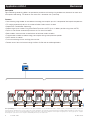
S1 = DHW Tank Sensor 078
S2 = Pressure Sensor 088 (Optional)
P1...P4 = Water Heater Pumps
P5 = DHW Recirculation Pump
Description
Four water heaters are operated to provide volume domestic hot water heating. A domestic hot water recirculation pump
operates on a programmable schedule.
Features:
• Proportional staging with adjustable boiler and interstage differentials and time delays provide rapid response to domestic
hot water heating loads.
• Equal run time rotation automatically balances the run time of the water heaters.
• Programmable schedule to reduces energy consumption during unoccupied time periods.
• Remote access from the Internet through the Watts OnSite web or mobile applications.
Legend
B1
P1
P5
S2
S1
P2P3P4
B2B3B4
294
Concept Drawing: This is only a concept drawing, not an engineered drawing. It is not intended to describe a complete system, nor any particular system. It is up to the
system designer to determine the necessary components for and configuration of the particular system being designed, including additional equipment, isolation relays (for
loads greater than the control’s specified output ratings), and any safety devices which in the judgement of the designer are appropriate, in order to properly size, configure
and design that system and to ensure compliance with building and safety code requirements.
Application A 294-6 Mechanical

A-T-294 2205 © 2022 tekmar 15
FCC ID: 2AHQR-11500A
Contains FCC ID:
2AC7Z-ESP32WROOM32E
QOQMGM12P0
Contains IC ID:
21098-ESPWROOM32E
5123A-MGM12P0
CAN ICES-3 (A)/NMB-3(A)
Class 2 Circuits
Boiler Mod:
Class 2 Circuits
Input Power:
115 V (ac) ±10%, 60 Hz, 9 W
Relays:
230 V (ac), 5 A, 1/3 hp
Calls:
24 V (ac) or Short
Operating Temperature:
32°F to 122°F (0°C to 50°C)
Use Copper Conductors Only
2827
Boiler 2
2625
Boiler 1
24
Ethernet
3029
Boiler 3
3231
Boiler 4
3433
Boiler 1
Enable
3635
Boiler 2
Enable
3837
Boiler 3
Enable
4039
Boiler 4
Enable
4241
Boiler 1
Pump/Vlv
4443
Boiler 2
Pump/Vlv
4645
Boiler 3
Pump/Vlv
4847
Boiler 4
Pump/Vlv
50
49
Comb
Air Relay
5251
System
Pump
5453
DHW
Pump
5655
Power
N
DANGER
DANGER
To Reduce the Risk of Electric
Shock - Do not connect to a
circuit operating at more than
150 volts to ground.
Pour réduire les risques
d'électrocution choc - ne pas
raccorder à un circuit
fonctionnant à plus de 150 V à
la terre.
L
54
Out Sens
76
Boiler
Sensor
98
DHW
Sensor
1110
Heat
1312
DHW
1514
Setpoint
1716
tN4
Boiler Bus
19 2018
+Gnd
Expansion
22 2321
ACB+Gnd
Boiler Modbus
231
Ref In Gnd
Pressure Sens
Mod
+Mod
+Mod
+Mod
+
Call
+Call
+Call
+
EMS
+
H2061B Smart Boiler Control 294
For product literature:
Pour la documentation
du produit:
Watts.com/tekmar
tektra 1150-01
Designed and assembled
in Canada
N
G
L
LNG LNG
LNG LNG
LNG
+-+-+-+-TT TT TT TT
B1...B4 = Water Heater On-Off Enable 1 to 4
E1 = Ethernet (Optional)
M1...M4 = Water Heater Modulating Signal 1 to 4
S1 = DHW Tank Sensor 078
Legend
B1M1 M2 M3 M4
P1 P5
S2 S1 E1
P2
P3
P4
B2 B3 B4
Concept Drawing: This is only a concept drawing, not an engineered drawing. It is not intended to describe a complete system, nor any particular system. It is up to the
system designer to determine the necessary components for and configuration of the particular system being designed, including additional equipment, isolation relays (for
loads greater than the control’s specified output ratings), and any safety devices which in the judgement of the designer are appropriate, in order to properly size, configure
and design that system and to ensure compliance with building and safety code requirements.
Application A 294-6 Electrical
S2 = Pressure Sensor 088 (Optional)
P1...P4 = Water Heater Pumps
P5 = DHW Recirculation Pump

The following are the recommended specifications for the Smart Boiler Control 294
• The control shall be capable of sequencing up to four single-stage, two two-stage, one three-stage, one four-stage or
four modulating boilers.
• The control shall be capable of operating modulating boilers using an analog 0 – 10 V(dc) or 4 – 10 mA signal.
• The control shall operate modulating boilers using an analog signal to change the boiler firing rate or the boiler
target temperature.
• The control shall be capable of operating combinations of condensing and non-condensing boilers.
• The control shall be capable of adjusting the boiler plant target to provide indirect domestic hot water heating with priority.
• The control shall have the ability to calculate the boiler plant target temperature based on outdoor temperature reset.
• The control shall have the ability to set the boiler plant target temperature using an adjustable setpoint.
• The control shall have the ability to set the boiler plant target temperature as directed by a BAS, BMS or EMS.
• The control shall have an adjustable warm weather shut down applied to outdoor temperature reset operation.
• The control shall be able to operate one primary pump and one domestic hot water pump during a domestic hot water call.
• The control shall have the option to measure fluid pressure.
• The control shall have an option to rotate the boilers based on the accumulated running hours.
• The control shall display the run time of the boilers.
• The control shall use proportional, integral and derivative (PID) logic when modulating or staging the boilers.
• The control shall have the option to modulate the boilers sequentially or in parallel.
• The control shall have an adjustable minimum supply water temperature setting to help prevent condensation of flue
gases and subsequent corrosion and blockage of the boiler’s heat exchanger and chimney.
• The control shall have the option of an automatic differential calculation in order to prevent short cycling of the boilers.
• The control shall have the option to have all of the boilers operate a pump or an isolation valve.
• The control shall have adjustable post purge settings that allow the primary and boiler pumps / valves to run for a set
period after the boiler has been shut off.
• The control shall have the option for fixed lead and fixed last boiler rotation.
• The control shall have the option to operate a combustion air damper output.
• The control shall have an adjustable minimum inter-stage delay that can be set manually or calculated by the control.
• The control shall have the option of accepting a 0 – 10 V (dc) or 2 – 10 V (dc) input signal from an energy management
system with an adjustable offset.
• The control shall have an optional passcode to prevent unauthorized access to the home screen and setting menus.
• The control shall have manual override options to test boiler and pump operation, suspend boiler plant operation, operate
pumps for purging and operate the system with a maximum heat output.
• The control shall have the ability to display the current outdoor, boiler supply, domestic hot water temperatures.
• The control shall continually monitor the temperature and pressure sensors and provide an error message upon a control
or sensor failure.
• During extended periods of inactivity, all pumps shall be periodically exercised to prevent seizure during long idle periods.
• The control shall include a setback schedule to provide energy savings during unoccupied time periods.
• The control shall have the option to operate as a tN4 system control with a tN4 boiler bus.
• The control shall display the current percent modulation of each boiler, or the number of stages fired.
• The control shall have the option to connect to the Internet using Ethernet or Wi-Fi.
• The control shall have the ability to automatically set the time and date from the Internet.
• The control shall have the ability to retrieve the local outdoor air temperature through the Internet.
• The control shall have the ability to be remotely monitored and adjust settings through a web and/or mobile application.
Specifications
A-T-294 2205 © 2022 tekmar
Tel: 1-800-438-3903 • Fax: (250) 984-0815
tekmarControls.com
All specifications are subject to change without notice
-
 1
1
-
 2
2
-
 3
3
-
 4
4
-
 5
5
-
 6
6
-
 7
7
-
 8
8
-
 9
9
-
 10
10
-
 11
11
-
 12
12
-
 13
13
-
 14
14
-
 15
15
-
 16
16


