
USER’S INFORMATION MANUAL
SERIES MI-e
®
GAS BOILERS
TO THE INSTALLER: This manual is the property of the owner and must be axed near the boiler for future
reference.
TO THE OWNER: This boiler should be inspected annually by a Qualied Service Agency.
TO BE COMPLETED BY THE INSTALLER
Service Agency Phone No.
Address
Boiler Model No. Serial No. Date of Installation:
– Do not store or use gasoline or other
ammable vapors and liquids in the vicinity
of this or any other appliance.
– WHAT TO DO IF YOU SMELL GAS
• Do not try to light any appliance.
• Do not touch any electrical switch;
do not use any phone in your building.
• Immediately call your gas supplier from
a neighbor’s phone. Follow the gas
supplier’s instrucons.
• If you cannot reach your gas supplier,
call the re department.
– Installaon and service must be performed
by a qualied installer, service agency or
the gas supplier.
If the informaon in this manual is not
followed exactly, a re or explosion may
result causing property damage, personal
injury or loss of life.
– Ne pas ranger ou uliser de la gazoline ou d’autres
liquides ou gaz inammables à proximité de cet
appareil ou d’un autre du même type.
– QUE FAIRE SI VOUS DÉTECTEZ UNE
ODEUR DE GAZ
• Ne pas tenter d’allumer l’appareil.
• Ne toucher à aucun interrupteur électrique ;
n’uliser aucun appareil téléphonique dans
l’immeuble.
• Contacter immédiatement votre fournisseur de
gaz à parr du téléphone d’un voisin. Suivre les
instrucons données par votre fournisseur de
gaz.
• S’il est impossible de rejoindre le fournisseur
de gaz, appeler le service
des incendies.
– L’installaon et l’entreen doivent être eectués
par un installateur qualié, une société d’entreen
ou le fournisseur de gaz.
PB HEAT, LLC
131 S. CHURCH ST • BALLY, PA 19503 MI8094 R2 (05/22-2M)
Printed in U.S.A.
©2022 PB Heat, LLC. All rights reserved.
Négliger de suivre ces instrucons à la lere
pourrait provoquer un incendie ou une explosion
causant des dégâts matériels, des blessures ou la
mort.
⚠MISE EN GARDE
⚠WARNING

2
Basic Operation
A. General. This water boiler is a natural dra appliance and is equipped with controls for proper operaon. All
controls must be in proper working order. Contact a qualied service agency to provide annual maintenance as
specied in Installaon, Operaon and Maintenance Manual.
1. Limit. See Figure 1. A device which automacally interrupts boiler operaon when the water temperature
exceeds the set point. Maximum allowable temperature is 240°F (115°C).
Boiler operaon is interrupted when system temperature reaches cut-out temperature. Boiler operaon
resumes automacally when system temperature falls approximately 15°F (8°C) below the cut-out
temperature. See also Figure 5 for limit sequence of operaon.
1A. Limit Control may incorporate a low water cut-o feature that will interrupt boiler operaon upon loss of
water in the boiler. If the low water cut-o funcon is acvated to interrupt boiler operaon, follow the
instrucons TO TURN OFF GAS TO THE APPLIANCE (see Figures 2, 3 & 4) and contact a qualied service
agency.
2. Flame Rollout Switch. See Figure 1. A device which automacally interrupts boiler operaon when ames
or excessive heat are present in the combuson area. The control is a single use device. If the control is
acvated to interrupt boiler operaon, do not aempt to place boiler in operaon. Contact a qualied
service agency.
3. Blocked Vent Switch (Vent Safety Shuto Switch). See Figure 1. A device which automacally interrupts
boiler operaon when there is a blockage in the vent pipe or chimney. The control is a manual reset
device. The control is located on the dra hood relief opening. If the control was acvated to interrupt
boiler operaon, do not aempt to place boiler in operaon. Contact a qualied service agency.
4. Pilot. The pilot provides the ignion source for the main burners. Your boiler has an intermient pilot. The
intermient pilot ignites only when there is a call for heat and exnguishes when the call for heat ends.
See Figure 6.
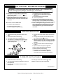
Should overheang occur or the gas supply fail to shut o, do not turn o or disconnect the electrical supply
to the pump. Instead, shut o the gas supply at a locaon external to the appliance.
Do not use this boiler if any part has been under water. Immediately call a qualied service agency to inspect
the boiler and to replace any part of the control system and any gas control which has been under water.
En cas de surchaue ou si l’alimentaon ne se coupe pas, ne pas éteindre manuellement ni couper
l’alimentaon électrique de la pompe. Couper plutôt l’alimentaon en combusble à l’extérieur
de l’appareil.
Ne pas uliser cee chaudière ni aucune de ses pièces si elles ont été immergées. Contactez
immédiatement une agence d’entreen qualiée pour inspecter la chaudière et remplacer toute
pièce du système de régulaon du débit gazeux et toute commande de gaz ayant été immergée.
⚠ CAUTION
Service on this boiler should be undertaken only by trained and skilled personnel from a qualied service
agency.
L’entreen de cee chaudière doit être eectué seulement par des employés qualiés et d’expérience
appartenant à une société d’entreen reconnue.
⚠ WARNING

3
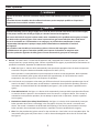
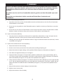
5. Gas Valve. The gas valve regulates gas ow to the burners and pilot. See Figure 1.
6. Safety Relief Valve. A device which protects the boiler against excessive pressure. The safety relief valve
can discharge a large amount of hot water - the installer should provide piping to discharge water near
oor at a oor drain. If the safety relief valve discharges water, follow instrucons TO TURN OFF GAS TO
APPLIANCE (see Figures 2, 3 & 4), and contact a qualied service agency.
TEMPERATURE-PRESSURE GAUGE
SAFETY RELIEF VALVE
BLOCKED VENT SWITCH
LIMIT
CONTROL
SENSOR
GAS VALVE
BURNER OBSERVATION OPENING
FLAME ROLLOUT
SWITCH
TRANSFORMER
LIMIT CONTROL
AUTOMATIC VENT DAMPER
Figure 1: Control Locaons
B. Instrucons to place boiler in operaon and to turn o the boiler are shown on the Operang or Lighng
Instrucon Label posted on the le side of the boiler. The instrucons are also shown in Figures 2, 3 & 4.
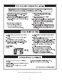
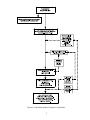
C. The Sequence of Operaon is shown in Figure 5.

4
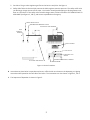
Figure 2: Intermient Ignion Operang Instrucons

5
Figure 3: Intermient Ignion Operang Instrucons

6
Figure 4: Operang Instrucons - Robershaw Gas Valve
WARNING: If you do not follow these instructions exactly, a fire or explosion may
result causing property damage, personal injury, or loss of life.
OPERATING INSTRUCTIONS
TO TURN OFF GAS TO APPLIANCE
1. Set the thermostat to lowest setting.
2. Turn off all electric power to the appliance if service is
to be performed.
3. If the gas valve is not visible, remove the control
access panel.
4. Turn the gas control knob clockwise
to "OFF".
5. Replace control access panel, if applicable.
7000 9363 REV 1
FOR YOUR SAFETY READ BEFORE OPERATING
A. This appliance is equipped with an ignition device
which automatically lights the pilot. Do not try to
light the pilot by hand.
B. BEFORE OPERATING smell all around the appliance
area for gas. Be sure to smell next to the floor
because some gas is heavier than air and will settle
on the floor.
WHAT TO DO IF YOU DO SMELL GAS
• Do not try to light any appliance.
• Do not touch any electric switch;
do not use any phone in your building.
Immediately call your gas supplier from a
neighbor’s phone. Follow the gas supplier’s
instructions.
If you cannot reach your gas supplier,
call the fire department.
C. Use only your hand to slide the gas control switch.
Never use tools. If the switch will not slide by hand,
don’t try to repair it, call a qualified service technician.
Force or attempted repair may result in a fire or explosion.
D. Do not use this appliance if any part has been under
water. Immediately call a qualified service technician
to inspect the appliance and to replace any part of the
control system and any gas control which has been
under water.
1. STOP! Read the safety information above on this
label.
2. Set the thermostat to lowest setting.
3. Turn off all electric power to the appliance.
4. This appliance is equipped with an ignition device
which automatically lights the pilot. Do not try to
light the pilot by hand.
5. If the gas valve is not visible, remove control access
panel.
6. If the gas control knob is not in the "OFF" position,
turn the knob clockwise
to "OFF".
7. Wait five (5) minutes to clear out any gas. If you then
smell gas, STOP! Follow "B" in the safety information
above on this label. If you don’t smell gas, go to the
next step.
8. Turn the gas control knob counterclockwise
to "ON".
9. Replace control access panel, if applicable.
10. Turn on all electrical power to the appliance.
11. Set thermostat to desired setting.
12. If the appliance will not operate, follow the
instructions "To Turn Off Gas To Appliance"
and call your service technician or gas supplier.

7
Figure 5: Intermittent Ignition Sequence of Operation

8
User Maintenance
Product Safety Informaon
Refractory Ceramic Fiber Product
This appliance contains materials made from refractory ceramic bers (RCF). Airborne RCF, when
inhaled, have been classied by the Internaonal Agency for Research on Cancer (IARC), as a
possible carcinogen to humans. Aer the RCF materials have been exposed to temperatures above
1800°F (980°C), they can change into crystalline silica, which has been classied by the IARC as
carcinogenic to humans. If parcles become airborne during service or repair, inhalaon of these
parcles may be hazardous to your health.
Avoid Breathing Fiber Parculates and Dust
Suppliers of RCF recommend the following precauons be taken when handling these materials:
Precauonary Measures:
Provide adequate venlaon.
Wear a NIOSH/MSHA approved respirator.
Wear long sleeved, loose ng clothing and gloves to prevent skin contact.
Wear eye goggles.
Minimize airborne dust prior to handling and removal by water misng the material and avoiding
unnecessary disturbance of materials.
Wash work clothes separately from others. Rinse washer thoroughly aer use.
Discard RCF materials by sealing in an airght plasc bag.
First Aid Procedures:
Inhalaon: If breathing diculty or irritaon occurs, move to a locaon with fresh clean air. Seek
immediate medical aenon if symptoms persist.
Skin Contact: Wash aected area gently with a mild soap and warm water. Seek immediate medical
aenon if irritaon persists.
Eye Contact: Flush eyes with water for 15 minutes while holding eyelids apart. Do not rub eyes. Seek
immediate medical aenon if irritaon persists.
Ingeson: Drink 1 to 2 glasses of water. Do not induce voming. Seek immediate medical aenon.
⚠ WARNING

9
A. General Housekeeping (Connuous).
1. Keep boiler area clear and free of combusble materials and obstrucons to the free ow of combuson
and venlaon air to the boiler.
2. Do not store or use gasoline or other ammable vapors or liquids in the vicinity of the boiler or any other
appliance.
3. Do not store or use sources of hydrocarbons in the vicinity of the boiler. Sources of hydrocarbons include
bleaches, cleaners, chemicals, sprays, paint removers, fabric soeners and refrigerants.
B. Inspect Vent System (Monthly)
1. Vent pipe must be connuous to chimney with no separaons, obstrucons, or sags. Vent pipe must be
supported at minimum 4 foot (122 cm) intervals and secured with sheet metal screws.
2. Chimney must not have signs of connuous wetness. If signs of connuous wetness are observed, contact
a qualied service agency.
C. Inspect Pilot and Main Burner Flames (Monthly).
1. Adjust thermostat to lowest seng.
2. Remove control access panel (lower front jacket panel) by liing and pulling out.
3. Adjust thermostat to highest seng. Verify operaon follows Sequence of Operaon (see Figure 5).
4. View ames through observaon port. See Figure 1.
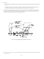
5. Check pilot ame. See Figure 6. The pilot ame should be medium blue covering approximately 3/8” to
1/2” (10 to 12 mm) of the sensing probe. If the ame is yellow and lazy, follow instrucons TO TURN OFF
GAS TO APPLIANCE (see Figures 2, 3 & 4) and contact qualied service agency.
6. Check main burner ames. See Figure 6. The ames should have clearly dened inner cones approximately
1-1/2” (40 mm) high and should have a very sharp blue color characterisc. If the ame is yellow and lazy,
follow instrucons TO TURN OFF GAS TO APPLIANCE (see Figures 2, 3 & 4) and contact qualied service
agency.
7. Adjust all thermostats to lowest seng to shut down boiler.
8. Replace control access panel.
9. Adjust thermostats to normal seng.
Service on this boiler should be undertaken only by trained and skilled personnel from a qualied
service agency. Inspecons should be performed at intervals specied in the Installaon, Operaon
and Maintenance Manual and this User’s Informaon Manual. Maintain manuals in a legible
condion.
Keep boiler area clear and free of combusble materials, gasoline and other ammable vapors and
liquids.
Do not place any obstrucons in boiler room that will hinder ow of combuson and
venlaon air.
⚠ WARNING

10
D. Controls
1. Safety Relief Valve. Conduct try lever test as outlined in manufacturer’s instrucon tag on the safety relief
valve.
2. Low Water Cut-o. Control manufacturer requires low water cut-o to be serviced every ve years by a
qualied service agency. See control manufacturer’s instrucons for further informaon.
E. General Inspecon and Maintenance (Annual). For connued safe operaon a qualied service agency must
provide a more detailed inspecon of burners, heat exchanger and vent system, and provide maintenance as
specied in the Installaon, Operaon and Maintenance Manual.
Figure 6: Intermient Ignion Pilot Conguraon and Flames
1 Controls maintenance may be part of annual inspecon and maintenance by a qualied service agency if annual frequency is specied by
controls manufacturer.
-
 1
1
-
 2
2
-
 3
3
-
 4
4
-
 5
5
-
 6
6
-
 7
7
-
 8
8
-
 9
9
-
 10
10


dans d''autres langues
- English: Peerless PEE0103001 User manual
Autres documents
-
Peerless Boilers 63 series Manuel utilisateur
-
U.S. Boiler Company 303BNI-T Mode d'emploi
-
U.S. Boiler Company ES28BPI-T Mode d'emploi
-
Crown Boiler BWC Series Mode d'emploi
-
-
-
-
-
Bradford White BJX075 Manuel utilisateur
-