
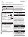
FOR YOUR SAFETY: This product must be installed and serviced by a professional service technician,
qualied in hot water boiler and heater installation and maintenance. Improper installation and/or operation
could create carbon monoxide gas in ue gases which could cause serious injury, property damage, or
death. Improper installation and/or operation will void the warranty.
WARNING
If the information in this manual is not followed
exactly, a re or explosion may result causing
property damage, personal injury or loss of life.
Do not store or use gasoline or other ammable
vapors and liquids in the vicinity of this or any
other appliance.
WHAT TO DO IF YOU SMELL GAS
• Do not try to light any appliance.
• Do not touch any electrical switch; do not use
any phone in your building.
• Immediately call your gas supplier from a
nearby phone. Follow the gas supplier's
instructions.
• If you cannot reach your gas supplier, call the
re department.
Installation and service must be performed by
a qualied installer, service agency, or gas supplier.
AVERTISSEMENT
Assurez-vous de bien suivres les instructions
données dans cette notice pour réduire au
minimum le risque d’incendie ou d’explosion ou
pour éviter tout dommage matériel, toute blessure
ou la mort.
Ne pas entreposer ni utiliser d’essence ni d’autres
vapeurs ou liquides inammables dans le voisinage
de cet appareil ou de tout autre appareil.
QUE FAIRE SI VOUS SENTEZ UNE ODEUR DE GAZ:
• Ne pas tenter d’allumer d’appareils.
• Ne touchez à aucun interrupteur. Ne pas vous servir des
téléphones dansle bâtiment où vous êtes.
• Appelez immédiatement votre fournisseur de
gaz depuis un voisin. Suivez les instructions du
fournisseur.
• Si vous ne pouvez rejoindre le fournisseur de gaz,
appelez le sservice des incendies.
L’installation et l’entretien doivent être assurés par un
installateur ou un service d’entretien qualié ou par le
fournisseur de gaz.
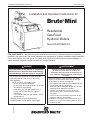
Residential
Gas-Fired
Hydronic Boilers
Sizes 50-200 MBTU/h
Installation and Operation Instructions for
Brute Mini
®
Installation and Operation Instructions Document 1490
H2413300

TABLE OF CONTENTS
SECTION 1 GENERAL INFORMATION
1.A Safety Warnings ..................................... 4
1.B Introduction ............................................. 6
1.C Warranty ................................................. 6
1.D Model Number and Nomenclature .........6
1.E Model Overview ...................................... 7
1.F Dimensions ............................................. 9
1.G The Installation Kit ................................ 10
1.H Accessory Kits Available.......................10
SECTION 2 LOCATING THE BOILER
2.A Field Assembly ..................................... 10
2.B Boiler Placement .................................. 10
2.C Clearances ........................................... 10
SECTION 3 AIR AND VENTING
3.A Safety Warnings ................................... 11
3.B Combustion Air Supply ......................... 12
3.C Venting .................................................13
3.D Vertical Venting - Category I ................ 14
3.E Locations for Vent Pipe Terminator....... 15
3.F Venting with a Power Venter ...............16
3.G Common Vent Test ............................... 16
SECTION 4 GAS CONNECTIONS
4.A Gas Supply and Piping ......................... 17
4.B LP Gas Conversion .............................. 18
4.C Special Precautions for LP Gas............ 18
SECTION 5 PUMP REQUIREMENTS
5.A Pump Sizing ......................................... 19
SECTION 6 WATER CONNECTIONS
6.A Water Piping ......................................... 20
6.B Low Loss Header .................................20
6.C Chilled Water Systems ......................... 20
6.D Oxygen Permeable Systems ................ 20
6.E Anti-freeze ............................................ 20
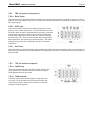
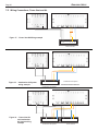
6.F Typical Plumbing Diagrams .................. 21
SECTION 7 ELECTRICAL AND
WIRING DIAGRAMS
7.A Safety Warnings ................................... 23
7.B Main Power, 120V ................................ 23
7.C Outdoor Sensor .................................... 23
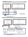
7.D Field Connections ..............................24
7.D.1 TB1 (Term Block 1 -TT, DHW, OAS) . 24
7.D.1.a TT (Central Heat).................................. 24
7.D.1.b DHW. ................................................... 24
7.D.1.c Field Interlocks ..................................... 24
7.D.1.d PV Terminals ....................................... 24
7.D.1.e WWSD + COM .................................... 24
7.D.1.f OAS ..................................................... 24
7.D.2 TB2 (for pumps and aux power) .......25
7.D.2.a Boiler Pump .......................................... 25
7.D.2.b SYS Pump ............................................ 25
7.D.2.c Aux Power ............................................ 25
7.D.3 TB3 (for optional equipment) ............ 25
7.D.3.a DHW Pump .......................................... 25
7.D.3.b DHW Aquastat ...................................... 25
7.E Wiring Connects, Power Vent and Air .. 26
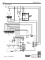
7.F Wiring Diagram ..................................... 28
7.G Logic Diagram ...................................... 29
SECTION 8 THE DIGITAL DASHBOARD
8.A Getting to know the Digital Dashboard.
8.A.1 Setting the Economy Feature ............... 30
8.A.2 High Limit (High Temp) ......................... 30
8.A.3 Low Limit (Advanced Options/Adjust) .. 30
8.A.4 Control LEDs ........................................ 31
8.A.4.a ACTIVE (TEMP) ................................. 31
8.A.4.b HI TEMP .............................................. 31
8.A.4.c ACTIVE (LWCO) .................................. 31
8.A.4.d LOW WATER ....................................... 31
8.A.4.e ACTIVE (ECONOMY) .........................31
8.A.4.f TARGET ............................................. 31
8.A.5 Digital LEDs .......................................... 31
8.A.6 Ignition LEDs ........................................ 31
8.A.6.a LIMITS ................................................. 31
8.A.6.b V-PWR .................................................. 31
8.A.6.c V-SW ................................................... 31
8.A.6.d FLAME .................................................32
8.B Default Settings. ................................32
8.C Advanced Settings .............................32
8.C.1 Programming the Outdoor Sensors ...... 32
8.C.1.a Setting the Outdoor Reset .................... 32
8.C.1.b Setting Warm Weather Shutdown ........ 32
8.C.1.d Thermal Boost ......................................33
8.C.2 Degrees Fahrenheit or Celsius ............. 34
BRADFORD WHITE

7.D Field Connections ..............................24
7.D.1 TB1 (Term Block 1 -TT, DHW, OAS) . 24
7.D.1.a TT (Central Heat).................................. 24
7.D.1.b DHW. ................................................... 24
7.D.1.c Field Interlocks ..................................... 24
7.D.1.d PV Terminals ....................................... 24
7.D.1.e WWSD + COM .................................... 24
7.D.1.f OAS ..................................................... 24
7.D.2 TB2 (for pumps and aux power) .......25
7.D.2.a Boiler Pump .......................................... 25
7.D.2.b SYS Pump ............................................ 25
7.D.2.c Aux Power ............................................ 25
7.D.3 TB3 (for optional equipment) ............ 25
7.D.3.a DHW Pump .......................................... 25
7.D.3.b DHW Aquastat ...................................... 25
7.E Wiring Connects, Power Vent and Air .. 26
7.F Wiring Diagram ..................................... 28
7.G Logic Diagram ...................................... 29
SECTION 8 THE DIGITAL DASHBOARD
8.A Getting to know the Digital Dashboard.
8.A.1 Setting the Economy Feature ............... 30
8.A.2 High Limit (High Temp) ......................... 30
8.A.3 Low Limit (Advanced Options/Adjust) .. 30
8.A.4 Control LEDs ........................................ 31
8.A.4.a ACTIVE (TEMP) ................................. 31
8.A.4.b HI TEMP .............................................. 31
8.A.4.c ACTIVE (LWCO) .................................. 31
8.A.4.d LOW WATER ....................................... 31
8.A.4.e ACTIVE (ECONOMY) .........................31
8.A.4.f TARGET ............................................. 31
8.A.5 Digital LEDs .......................................... 31
8.A.6 Ignition LEDs ........................................ 31
8.A.6.a LIMITS ................................................. 31
8.A.6.b V-PWR .................................................. 31
8.A.6.c V-SW ................................................... 31
8.A.6.d FLAME .................................................32
8.B Default Settings. ................................32
8.C Advanced Settings .............................32
8.C.1 Programming the Outdoor Sensors ...... 32
8.C.1.a Setting the Outdoor Reset .................... 32
8.C.1.b Setting Warm Weather Shutdown ........ 32
8.C.1.d Thermal Boost ......................................33
8.C.2 Degrees Fahrenheit or Celsius ............. 34
8.C.3 Manual Reset Low Water Cut-O ......... 34
8.C.4 Low water Cut-O ................................ 34
8.C.5 High Limit Dierential ........................... 34
8.C.6 Restore Factory Default Settings .........34
8.D TEST / SETTINGS Button ..................35
8.E Temperature and Pressure Gauge ....35
SECTION 9 INITIAL STARTUP
9.A Filling the System ................................. 36
9.B System Start Up (Seq of Operation) ..... 36
9.C Proper Pilot Flame ................................ 38
9.D Lighting Instructions Decal ................... 39
9.E System Shutdown ................................40
SECTION 10 MAINTENANCE
10.A Removing the covers and panels ......... 40
10.A.1 Access Cover Removal ...................... 40
10.A.2 Flue Collector Access .......................... 40
10.A.3 Side Panel Removal ............................ 41
10.A.4 Draft Hood Removal ........................... 41
10.B Maintenance ......................................... 42
SECTION 11 OPERATING DETAILS AND
TROUBLESHOOTING
11.A Operating Details .................................. 43
11.B Electrical Troubleshooting .................... 43
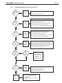
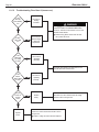
11.C Troubleshooting Table .......................... 44
11.C.1 Troubleshooting Flow Chart 1 (burners o) 45
11.C.2 Troubleshooting Flow Chart 2 (burners on) 46
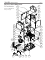
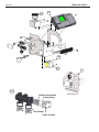
SECTION 12 REPLACEMENT PARTS
12.A Parts Illustrations .................................. 47
12.B Parts List ..............................................49
12.C Accessories List ...................................50
12.D Glossary of Terms................................. 51
RESIDENTIAL BOILERS
Brute-Mini
®

Page 4
1.A Safety Warnings
WARNING
Carbon Monoxide Hazard
Improper adjustment of the burners may lead to poor
combustion quality, increasing the amount of carbon
monoxide produced. Excessive carbon monoxide
levels may lead to personal injury or death.
WARNING
This unit must be installed in accordance with the
procedures detailed in this manual, or the manufacturers
warranty will be voided. The installation must conform
to the requirements of the local jurisdiction having
authority, and, in the United States, to the latest edition
of the National Fuel Gas Code, ANSI Z223.1/NFPA54.
In Canada, the installation must conform to the latest
edition of CSA B149.1 Natural Gas and Propane Gas
Installation Code, and/or local codes. Where required
by the authority having jurisdiction, the installation of
these units must conform to the Standard for Controls
and Safety Devices for Automatically Fired Boilers,
ANSI/ASME CSD-1. Any modi cations to the boiler, its
gas controls, or wiring may void the warranty. If eld
conditions require modi cations, consult the factory
representative before initiating such modi cations.
WARNING
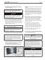
• Water temperature over 125°F (52°C) can cause
severe burns instantly or death from scalds.
• Children, disabled and
elderly are at highest
risk of being scalded.
• See instruction manual
before setting temperature
at the unit.
• Feel water before bathing
or showering.
• If this unit is used
to produce water that could scald if too hot, such
as domestic hot water use, adjust the outlet control
(limit) or use temperature limiting valves to obtain a
maximum water temperature of 125°F (52°C).
WARNING
The inlet gas pressure to the unit must not
exceed 13” W.C. (3.2kPa).
WARNING
Fire or Explosion Hazard
Improper con guration can cause fuel buildup and
explosion. Improper user operation may result in
property loss, severe physical injury, or death.
Any changes to safety-related con guration
parameters must only be done by experienced and/or
licensed burner/boiler operators and mechanics.
If any odor of gas is detected, or if the gas burner does
not appear to be functioning in a normal manner, close
the main gas shuto valve. Do not shut o the power
switch. Contact your heating contractor, gas company,
or factory representative.
NOTE: This unit is protected against hydronic
over-pressurization. A pressure relief valve is included
with each unit.
WARNING
Indicates an imminently hazardous situation which, if not
avoided, can or will result in death or serious injury and can
or will result in catastrophic property damage.
CAUTION
Indicates a potentially hazardous situation which, if not avoided,
may result in moderate injury and/or property damage.
NOTE:
Indicates instructions that are important to that topic but not
related to personal injury or property damage.
Safety Warnings are used throughout this manual to bring attention to the presence of hazards with various
risk levels and to o er important information concerning the life of this product. There are 3 basic types.
WARNING
CANCER AND REPRODUCTIVE HARM.
WWW.P65WARNINGS.CA.GOV.
AS REQUIRED BY THE STATE OF
CALIFORNIA PROPOSITION 65.
1
2
3
SECTION 1 GENERAL INFORMATION
BRADFORD WHITE

Page 5
WARNING
Electrical Shock Hazard
Electrical shock can cause severe injury, death or
property damage. Disconnect the power supply before
beginning installation or changing the wiring to prevent
electrical shock or damage to the equipment. It may be
necessary to turn o more than one power supply
to disconnect.
All electrical wiring is to be done in accordance with
local codes, or in the absence of local codes, with: 1)
The National Electrical Code ANSI/NFPA No. 70 - latest
Edition, or 2) CSA STD. C22.1 “Canadian Electrical Code
- Part 1.” This appliance must be electrically grounded in
accordance with these codes.
WARNING
The Repair Parts list designates parts that contain
refractory ceramic bers (RCF). RCF has been classi ed
as a possible human carcinogen. When exposed to
temperatures above 180ºF, such as during direct ame
contact, RCF changes into crystalline silica, a known
carcinogen. When disturbed as a result of servicing or
repair, these substances become airborne and, if inhaled,
may be hazardous to your health.
Do not remove or replace RCF parts or attempt any
service or repair work involving RCF without wearing
the following protective gear:
1. A National Institute for Occupational Safety and
Health (NIOSH) approved respirator.
2. Long sleeved, loose tting clothing.
3. Gloves.
4. Eye Protection.
WARNING
Should overheating occur or the gas supply fail to
shut o , do not turn o or disconnect the electrical
supply to the pump. Instead, shut o the gas supply
at a location external to the appliance.
AVERTISSEMENT
En cas de surchau e au si !’admission de gaz ne
peut etre coupee, ne pas couper ni debrancher
l’alimentatio electrique de la pompe. Fermer plutot
le robinet d’admission de gaz a l’exterieur de
l’appareil.
RESIDENTIAL BOILERS
Brute-Mini
®

Page 6
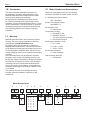
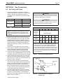
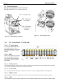
Consult the rating plate on the unit. The following
information describes the model number structure.
1.B Introduction
1.C Warranty
Model Nomenclature
1.D Model Number and Nomenclature
1C. Model Number and Nomenclature
The rating plate on the side of your Mini-Therm shows your Model Number. The original characteristics of
your unit can be identified using this nomenclature from your Model Number.
0 1 2 3 4 5 6 7
8
9 10
SIZE
0
5
0
0
7
5
1
0
0
1
2
5
1
5
0
2
0
0
Table 1. Nomenclature.
BJX = Mini-Therm Series
3
RD
thru 5th Characters (Size) Input MBTU / HR
6th Character (fuel)
N = Natural Gas
7th Configuration
X
N
X
L
P
U
1
BRADFORD WHITE
Bradford White Brute-Mini's are covered by a limited
warranty. The owner should complete the warranty
registration at www.BradfordWhite.com.
All warranty claims must be made to an authorized
Bradford White representative. Claims must include the
serial number and model (this information can be found
on the rating plate), installation date, and name of the
installer. Shipping costs are not included in the warranty
coverage.
Some accessory items may be shipped in separate
packages. Verify receipt of all packages listed on the
packing slip. Inspect everything for damage immediately
upon delivery, and advise the carrier of any shortages
or damage. Any such claims should be led with the
carrier. The carrier, not the shipper, is responsible for
shortages and damage to the shipment whether visible
or concealed.
The warranty does not cover damage caused by
improper assembly installation, operation or eld
modication.
This manual provides information necessary for
the installation, operation, and maintenance of the
Bradford White Brute-Mini residential boiler. Read it
carefully before starting the installation.
All application and installation procedures should
be reviewed completely before proceeding with the
installation. Consult the Bradford White factory, or local
factory representative, with any problems or questions
regarding this equipment. Experience has shown that
most operating problems are caused by improper
installation.
0 - 2nd Characters (Series Name)
BJX = Brute Mini
3rd thru 5th Characters (Size)
Input MBTU / H
6th Character (fuel)
N = Natural Gas
7th Character (Cong)
X = Standard 50-100
L = Standard 125-200
(Low Loss Header & Pump Installed)
P = 50-100 with Pump Kit
8th Character (Altitude in Feet)
X = (0 - 2,000)
H = (2,001 - 5,000)
I = (5,001 - 8,000)
9th Character (Country)
U = USA & Canada
10th Character (Revision)
1 = 1st Revision

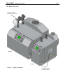
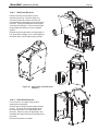
Page 7
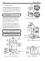
Figure 1. Largest and Smallest
200 MBH
Rating Plate
w/ Model Number
and Nomenclature
Low Loss Header.
Models 125 - 200 only
50 MBH
1.E Model Overview
RESIDENTIAL BOILERS
Brute-Mini
®

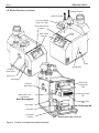
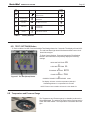
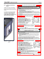
Page 8
User Control
Interface
Panel
Lock
Temp and Pressure
Gauges
Drain
Rating Plate
Pressure
Relief Valve
Pressure
Relief Valve
‘Knock-outs’
Gas Supply
Gas Supply
Main Power 120V
Connections
See 7.B on page 23
See 7.D on page 24
Gas Valve
Pilot Ignitor
Sensor
Shown with front cover o
Field Connections
TB1
DHW Relay
Connections
TB3
Field Connections
TB2
Low Loss Header
(sizes 125 - 200)
Hydronic Supply
Hydronic Return
Figure 2. Location of Components (model 100 shown)
1.E Model Overview (continued)
BRADFORD WHITE

Page 9
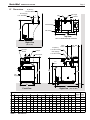
Table 1. Dimensions
1.F Dimensions
Dimensional
Data
1-1/4” NPT Female
OUT (Supply)
IN (Return)
1-1/4” NPT Female
53cm
23cm
F2
11.8cm
4-5/8"
21"
9-1/8" Max
E
Right View
(125, 150, 200)
OUT (Supply)
IN (Return)
1-1/4” NPT Male
1-1/4” NPT Male
F1
7"
18cm
Right View
(50, 75, 100)
In Return
Top View
Low Loss Header & Damper not shown
T&P Gauge
Control Display
PRV
Out Supply
C
WATER
CONN
GAS
CONN
SIZE
A B C D E
F1 F2
in. cm in, cm in. cm in, cm in. cm in. cm in. cm in.
(inches)
(inches)
cm 1-1/4
3/4
50 11-3/4 30 31-5/8 80 25-1/8 64 24-3/4 63 27-5/8 70 24-7/8 63
- -
4 10 1-1/4
3/4
75 14-1/2 37 31-5/8 80 25-5/8 65 24-3/4 63 28-5/8 73 24-7/8 63
24-7/8 63
- -
- -
5 13 1-1/4
3/4
100 17-3/8 45 32-1/8 82 25-1/2 65 25-3/8 65 28-5/8 73 5 13 1-1/4
3/4
125 20-1/8 52 32-1/8 82 25 64 25-3/8 65 28-5/8 73 -
-
31 79 6 15 1-1/4
3/4
150 23 59 32-1/8 82 25 64 25-3/8 65 28-5/8 73 -
-
31 79 6 15 1-1/4
3/4
200 28-3/8 73 32-1/4 82 24-5/8 63 26-1/4 67 28-5/8 73 -
-
31 79 7 18 1-1/4
3/4
Front View
Draft Diverter
Damper
6”
3-1/4” 8.3cm
Low Loss
Gas
Supply
Header
A
D
B
V
V
1-1/4” NPT Female
OUT (Supply)
IN (Return)
1-1/4” NPT Female
53cm
23cm
F2
11.8cm
4-5/8"
21"
9-1/8" Max
E
Right View
(125, 150, 200)
OUT (Supply)
IN (Return)
1-1/4” NPT Male
1-1/4” NPT Male
F1
7"
18cm
Right View
(50, 75, 100)
In Return
Top View
Low Loss Header & Damper not shown
T&P Gauge
Control Display
PRV
Out Supply
C
WATER
CONN
GAS
CONN
SIZE
A B C D E
F1 F2
in. cm in, cm in. cm in, cm in. cm in. cm in. cm in.
(inches)
(inches)
cm 1-1/4
3/4
50 11-3/4 30 31-5/8 80 25-1/8 64 24-3/4 63 27-5/8 70 24-7/8 63
- -
4 10 1-1/4
3/4
75 14-1/2 37 31-5/8 80 25-5/8 65 24-3/4 63 28-5/8 73 24-7/8 63
24-7/8 63
- -
- -
5 13 1-1/4
3/4
100 17-3/8 45 32-1/8 82 25-1/2 65 25-3/8 65 28-5/8 73 5 13 1-1/4
3/4
125 20-1/8 52 32-1/8 82 25 64 25-3/8 65 28-5/8 73 -
-
31 79 6 15 1-1/4
3/4
150 23 59 32-1/8 82 25 64 25-3/8 65 28-5/8 73 -
-
31 79 6 15 1-1/4
3/4
200 28-3/8 73 32-1/4 82 24-5/8 63 26-1/4 67 28-5/8 73 -
-
31 79 7 18 1-1/4
3/4
Front View
Draft Diverter
Damper
6”3-1/4” 8.3cm
Low Loss
Gas
Supply
Header
A
D
B
V
V
RESIDENTIAL BOILERS
Brute-Mini
®

Page 10
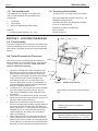
Figure 3. Minimum Clearances
SECTION 2 LOCATING THE BOILER
2.A Field Assembly
This boiler is shipped with an automatic vent damper that
must be assembled onto the vent collar on the top of the
boiler, and then plugged into the unit using the dedicated
harness.
2.B Boiler Placement and Clearances
This boiler is design certied by CSA-International for
indoor installation on combustible ooring, in basements,
in closets, utility rooms or alcoves. These units must
never be installed on carpeting.
1. This boiler is designed for indoor installations only
and should be located to provide clearances on all
sides for maintenance and inspection. See Figure
3. It should not be located in an area where leakage
of any connections will result in damage to the
area adjacent to the unit or to lower oors of the
structure. When such a location is not available, it is
recommended that a suitable drain pan, adequately
drained, be installed under the unit.
2. A minimum of 15” (381mm) access must be available
in front of the boiler for burner removal. Consult
local codes for clearances to hot water pipes and
accessories.
3. If the boiler is to be installed in a garage, all burners
and burner ignition devices must have a minimum 18”
(457mm) clearance above the oor.
4. Boilers can be installed in a closet as long as all
minimum clearances are followed, including between
the front of the boiler and the closet door when it is
closed. See Figure 3. Consult the American National
Standard Z21.13 for more information concerning
closet installations. In Canada, refer to the latest
edition of CSA-B149.1.
5. When vented vertically, the unit must be located as
close as practical to the vertical section of the vent.
When a power venter is used with a terminal through
a wall, and there is a potential for snow accumulation,
the terminal must be installed at an appropriate level
above grade or the maximum expected snow
line.
NOTE: For installation on combustible ooring.
Installer seulement sur un plancher
combustible.
NOTE: For Closet Installation Clearances, the
minimum clearance between hot water pipes
and combustible construction is 1” (2.5 cm.)
BRADFORD WHITE
4” 10 cm
4” 10 cm
6” 15 cm
20” 51 cm
2” 5 cm
1.G The Installation Kit
This residential unit is shipped in a single crate
with a boxed installation kit that contains these
components.
1. I/O Manual
2. Vent Damper
3. Burner Air Bae Gauge (Mini Gauge)
Optional:
1. Circulator pump & ange kit (50 - 100)
1.H Accessory Kits Available
See Section 12.C on page 50 for part numbers.
• Low Loss Header with Integral Pump for 50 - 100
(Standard on larger models)
• Conversion kits for LP and altitude are available
from 0 to 10,000’ both fuels.
• Domestic Hot Water Pump Relay Kit
• Power Vent Kits
• Outdoor Air Sensor

Page 11
SECTION 3 Air and Venting
3.A Safety Warnings
WARNING
For Category I, II and IV boilers, have horizontal runs
sloping upwards not less than ¼ inch per foot (21 mm/m)
from the boiler to the vent terminal.
AVERTISSEMENT
les chaudiE!res de categf)ries I, II et IV doivent
presenter des troni;ons horizontaux dont la pente
montante est d'au mains ¼ po par pied (21 mm/m) entre
la chaudiere et l'event.
WARNING
Damper must be in open position when appliance main
burner(s) is operating.
For use only with automatic vent damper device.
Follow installation instructions.
This boiler needs fresh air for safe operation and
must be installed so there are provisions for adequate
combustion and ventilation air.
AVERTISSEMENT
Le registre doit etre ouvert lorsque le brÛleur principal
de l'appareil fonctionne.
Pour utilisation avec un registre de conduit
d'evacuation automatique, Suivre les instructions
d'installation.
Cette chaudiere doit étre alimente en air frais pour
fonctionner en toute securite et doit etre installee de
fai;on que la combustion et l'alimentation en air de
ventilation soient adequates.
WARNING
This boiler must be vented in accordance with Part
7, Venting of Equipment, of the latest edition of the
National Fuel Gas code, NFPA 54/ANSI Z223.1
and all applicable local building codes. In Canada,
follow CAN/CGA B149 Installation codes. Improper
venting of this appliance can result in excessive
levels of carbon monoxide which can result in
severe personal injury or death!
AVERTISSEMENT
Cette chaudière doit être ventilé, conformément
aux dispositions de la partie 7, de la ventilation de
l'équipement, de la dernière édition du National
gaz carburant code, NFPA 54/ANSI Z223.1 et tous
les codes du bâtiment locaux. Au Canada, CAN/
CGA B149 codes d'installation. Une mauvaise
ventilation de cet appareil peut entraîner des
niveaux excessifs de monoxyde de carbone qui
peut entraîner de graves blessures ou la mort!
WARNING
Operation of appliances with a blocked common
vent may lead to serious injury or death. Safety
devices must be implemented to prevent blocked
common vent operation. If safe operation of all
appliances connected to a common vent cannot
be assured, including prevention of spillage of ue
gasses into living spaces, common venting should
not be applied, and appliances should each be
vented separately.
AVERTISSEMENT
Le fonctionnement des appareils avec un système
d’évacuation bloqué peut provoquer des blessures
graves, voire la mort. Des dispositifs de sécurité
doivent être installés pour éviter le blocage des
systèmes d’évacuation. Si le fonctionnement
de tous les appareils connectés à un système
d’évacuation commun ne peut pas être assuré,
y compris la prévention de la dispersion des gaz
toxiques dans les espaces habités, on ne devrait
pas installer un système d’évacuation commun et
chaque appareil devrait être ventilé séparément.
RESIDENTIAL BOILERS
Brute-Mini
®

Page 12
BRADFORD WHITE
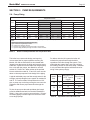
The information in Table 2 is not applicable in
installations where exhaust fans or blowers of any
type are used. Such installations must be designed by
qualied engineers.
Mechanical Combustion Air Systems: If a blower or
fan or automatic louvers are used to supply air to the
boiler room, the installer should make sure it does not
create drafts which could cause nuisance shutdowns. If
a blower is necessary to provide adequate combustion
air to the boiler, a suitable switch or equivalent must
be wired into the boiler control circuit to prevent the
boiler from ring unless the blower is operating. See
"7.E Wiring Connections, Power Vent and Air" on page
26 for wiring diagram.
The boiler must be completely isolated and
protected from any source of corrosive chemical
fumes such as those emitted by trichloroethylene,
perchloroethylene, chlorine, etc.
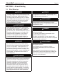
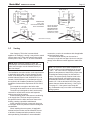
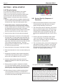
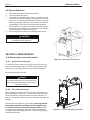
Figure 4. Chimney Venting (clay lined). Figure 5. Vertical Venting (vent or manufactured
chimney lining system).
CHIMNEY
LINER
THIMBLE
BOILER
CLEAN-
OUT
CHIMNEY
LINER
BOILER
THIMBLE
1/4"
PER FT.
(20mm PER M)
SLOPE
1/4"
PER FT.
(20mm PER M)
SLOPE
12" (305mm)
3.B Combustion Air Supply
The boiler location must provide sucient air
supply for proper combustion, and ventilation of the
surrounding area as outlined in the latest edition of U.S.
ANSI standard Z223.1 or in Canada, CAN/CGA-B149.1
or .2, and any local codes that may be applicable.
In general, these requirements specify that the boiler
rooms which represent conned spaces should be
provided with two permanent air supply openings; one
within 12 inches (305mm) of the ceiling, the other within
12 inches (305mm) of the oor.
NOTE: In Canada, follow Canadian Standard, CAN/
CGA-B149 or local codes.
Outside Air Supply: When combustion air is
supplied directly through an outside wall, each opening
should have a minimum free area of one square inch
per 4,000 BTU/h (6 sq. cm per 1.2 kW) input of the total
input rating of all appliances in the enclosed area.
Inside Air Supply: When combustion is supplied
from inside the building, each opening should have a
minimum free area of one square inch per 1,000 BTU/h
(6 sq. cm per 0.3 kW) input of the total input rating of all
appliances in the enclosed area. These openings should
never be less than 100 square inches (645 sq. cm).
Exhaust Fans or Vents: Any equipment which
exhausts air from the boiler room can deplete the
combustion air supply or reverse the natural draft action
of venting system. This could cause ue products to
accumulate in the boiler room. Additional air must be
supplied to compensate for such exhaust.
Table 2. Minimum Recommended
Air Supply to Boiler Room
Boiler Size Outside Air Area Inside Air Area
sq. in
sq. cm
sq. in.
sq. cm
50
15
97
100
645
75
20
129
100
645
100
25
161
100
645
125
32
206
125
807
150
40
245
150
980
200
50
323
200
1290
*Area indicated is for one of two openings: one at floor level
and one at the ceiling, so the total net free area would be
double the figures shown. For special conditions, refer to
NFPA54 ANSI Z223.1. In Canada, refer to the National
Standard CAN1-B149.1 or .2, which
differs from this table.
NOTE: Check with louver manufacturers for Net Free Area of
Louvers. Correct for screen resistance to the Net Free Area if a
screen is used.
CLEAN-
OUT

Page 13
RESIDENTIAL BOILERS
Brute-Mini
®
WALL OR
PARAPET
CHIMNEY
CHIMNEY
RIDGE
WALL OR
PARAPET
CHIMNEY
CHIMNEY
RIDGE
10 (3.0) OR
LESS
Figure 6. Vertical Vent Termination.
2 (0.6) MIN.
3 (0.9)
MIN.
10 (3.0)
OR LESS
2 (0.6)
MIN.
3 (0.9)
MIN.
3 (0.9)
MIN.
3 (0.9)
MIN.
2 (0.6)
MIN.
10 (3.0)
MORE THAN 10
(3.0)
MORE THAN 10
(3.0)
NOTE: NO HEIGHT
ABOVE PARAPET
REQUIRED WHEN
FROM WALLS OR
PARAPET IS MORE
THAN 10 FT. (3.0m)
TERMINATION
10 FT. (3.0m)
OR LESS FROM RIDGE,
WALL OR PARAPET
Dimensions in feet (m).
3.C Venting
Vent Category: This boiler is a natural draft
appliance for Category I venting. It may also be vented
using a power vent. Follow the instructions provided
with the power venter. See 3.F for more information.
NOTE: When venting a Category I boiler, the
vent damper must be fastened directly to the vent
collar, and vent pipe must be fastened directly to
the vent damper.
The installation must also conform to the requirements
of applicable local codes, or in the absence of such
codes, to the National Fuel Gas Code, ANSI Z223.1
and the National Electric Code, ANSI NFPA 70, or in
Canada, CAN/CGA B149.1 (a vent damper may not
be required in all Canadian jurisdictions) and B149.2
Installation Codes and the requirement of CSA C22.1,
Part 1.
Do not weld the vent pipe to the boiler collar.
The weight of the stack must not rest on the boiler.
The boiler top is designed so that it can be easily
removed for normal boiler service and inspection
without removal of the venting.
Avoid terminating boiler vents near air conditioning
or air supply fans. The fans can pick up exhaust
ue products from the boiler and return them to the
building, creating a possible health hazard.
Avoid oversized vent pipe or extremely long runs
of vent pipe, which may cause excessive cooling and
condensation.
When installing the vent system, all applicable
national and local codes must be followed! The use
of thimbles, restops and other protective devices,
when penetrating combustible or noncombustible
construction, must be in accordance with all applicable
national and local codes.
An unused lined chimney can be used as a
raceway for single wall vent pipe. Never run vent pipe
through a ue that has another appliance attached to
it.
NOTE: The minimum return water temperature of
the unit, in order to avoid condensation in the vent,
is 130°F. The unit's control is equipped to protect
against low temperatures, however the pumps must
be installed and wired properly for this feature to
function. The system pumps must be wired to the
system pump terminals, and a boiler pump must
be installed and wired to the boiler pump terminal
(models 125 - 200 are built with LLH/ boiler pump
systems that are wired at the factory). See Figure
21 on page 27. If the system is not setup this
way, condensation may occur which could damage
venting systems.

Page 14
BRADFORD WHITE
3.D Vertical Venting - Category I
All venting must comply with fuel gas code and
be installed by a licensed installer.
This boiler can be vented into a masonry chimney,
(see Figure 4 and Figure 5 on page 12) provided
several conditions are met:
1. The chimney must have an appropriate lining that
is clean, properly constructed and properly sized.
2. The chimney passage way shall be examined to
ascertain that it is clear and free of obstructions.
3. If a chimney rebuild is required, it shall conform
to nationally recognized standards (see National
Building Code or ANSI/NFPA 211).
4. The boiler must not be connected to a replace,
wood stove or other solid fuel burning equipment.
5. When the boiler and a hot water heater are to be
connected to the same chimney, they must have
their own vent connector and enter the chimney at
least 6” (152mm) apart.
IMPORTANT NOTE: Always provide a minimum
clearance of 6” (152mm) between Type C (single
wall) vent pipe and any combustible materials.
NOTE: Exterior masonry chimneys in very cold
environments are at risk of condensing due to the
high eciency of this equipment. Insulated liners
are recommended based on local conditions and
expected system water temperatures. Also ensure
the boiler’s anti-condensing features are utilized by
properly wiring the system pumps. See Figure 20. or
Figure 21 on page 27
WARNING
Do not store any chemical, cleaners, or other
corrosive material near combustion air openings
or in the room. Avoid locating dryer vents in the
vicinity of combustion air openings. Failure to
prevent corrosive materials from mixing with
combustion air can result in reduced boiler life
and unsafe boiler operation.
AVERTISSEMENT
N’entrepposer aucun produit chimique, produit
nettoyant ou produit corrosif à proximité des
bouches d’air de combustion ou dans la pièce.
Éviter de placer des tuyaux de ventilation pour
sécheuse à proximité des bouches d’air de
combustion. Le fait de laisser des maitières
corrosives se mélanger à l’air de combustion
risque de réduire le cycle de vie de l’appareil
de chauage et de compromettre son
fonctionnement.
WARNING
Single wall vent pipe must NEVER pass through
interior walls or through oors or ceilings! Failure
to comply with this warning could result in a re
causing property damage, personal injury, or death!
AVERTISSEMENT
Paroi simple tuyau d'évent doit jamais passer par
l'intérieur les murs ou par planchers ou plafonds
! Le non-respect de cet avertissement peut
provoquer un incendie causant des dommages
matériels ou corporels, ou de mort!

Page 15
RESIDENTIAL BOILERS
Brute-Mini
®
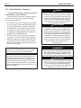
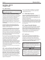
Figure 7.
Combustion Air and Vent Through Side Wall
*When vent terminal is less than 10 feet (3m)
horizontally from a forced air inlet, the terminal
must be at least 3 feet (0.9m) above the air inlet.
(US only)
† A vent shall not terminate directly above a sidewalk or paved driveway that is located between two single family dwellings and serves both dwellings.
‡ Permitted only if veranda, porch, deck, or balcony is fully open on a minimum of two sides beneath the oor.
Notes:
1) In accordance with the current CSA B149.1, Natural Gas and Propane Installation Code.
2) In accordance with the current ANSI Z223.1/NFPA 54, Natural Fuel Gas Code.
3) If locally adopted installation codes specify clearances dierent than those illustrated, then the most stringent clearance shall prevail.
4) For clearances not specied in CAN/CSA-B149, clearance is in accordance with local installation codes and the requirements of the gas supplier.
5) For clearances not specied in ANSI Z223.1/ NFPA 54, clearance is in accordance with local installation codes and the requirements of the gas supplier.
6) IMPORTANT: Terminal must be placed such that it remains a minimum of 12” above maximum expected snow line. Local codes may have more specic
requirements, and must be consulted.
A = Clearance above grade, veranda, porch,
deck, or balcony
)mc 03( ni 21)mc 03( ni 21
B = Clearance to window or door that may be
opened
● 6 in (15 cm) for appliances ≤ 10,000 Btuh (3 kW)
● 12 in (30 cm) for appliances > 10,000 Btuh (3 kW) and
≤ 100,000 Btuh (30 kW)
● 36 in (91 cm) for appliances >100,000 Btuh (30 kW)
● 6 in (15 cm) for appliances ≤ 10,000 Btuh (3 kW)
● 9 in (23 cm) for appliances > 10,000 Btuh (3 kW) and
≤ 50,000 Btuh (15 kW)
● 12 in (30 cm) for appliances >50,000 Btuh (15 kW)
wodniw desolc yltnenamrep ot ecnaraelC= C
D = Vertical clearance to ventilated soffit located
above the terminal within a horizontal
distance of 2 ft (61 cm) from
the center line of the terminal
tiffos detalitnevnu ot ecnaraelC = E
renroc edistuo ot ecnaraelC = F
See Note 4
See Note 4
See Note 4
See Note 4
See Note 4
See Note 5
See Note 5
See Note 5
See Note 5
See Note 5
See Note 5
See Note 5
See Note 5
ren
roc edisni ot ecnaraelC = G
H = Clearance to each side of centerline
extended above meter / regulator assy
3 ft (91 cm) within a height of 15 ft (4.6 m)
)mc 19( tf 3teltuo tnev rotaluger ecivres ot ecnaraelC = I
J = Clearance to nonmechanical air
supply inlet to building or the
combustion air inlet to any
other appliance
●
6 in (15 cm) for appliances ≤ 10,000 Btuh (3 kW)
●
12 in (30cm) for appliances > 10,000 Btuh (3 kW) and
≤ 100,000 Btuh (30 kW)
●
36 in (91 cm) for appliances > 100,000 Btuh (30 kW)
●
6 in (15 cm) for appliances ≤ 10,000 Btuh (3 kW)
●
9 in (23cm) for appliances > 10,000 Btuh (3 kW) and
≤ 50,000 Btuh (15 kW)
●
12 in (30 cm) for appliances > 50,000 Btuh (15 kW)
K = Clearance to a mechanical air
su
pp
l
y
inle
t
nihtiw fi evoba )mc 19( tf 3)m 38.1( tf 6
10 ft
(
3 m
)
horizontall
y
L = Clearance above paved sidewalk or paved
driveway located on public property
I yrogetaC( smetsys tfard lacinahcem rof )m 31.2( tf 7†)m 31.2( tf 7
appliances). Vents for Category II and IV appliances
cannot be located above public walkways or other
areas where condensate or vapor can cause a nuisance
or hazard*
M = Clearance under veranda, porch, deck, or
balcony
‡)mc 03( ni 21
* The manufacturer shall specify a minimum clearance or state "Not applicable" in the table and/or instructions.
i) The minimum distance from adjacent public walkways, adjacent buildings, openable windows, and building
openings shall not be less than those values specified in the National Fule Gas Code, ANSI Z223.1/NFPA 54,
and/or the Natural Gas and Propane Installation Code, CSA B149.1;
ii) Information on preventing blockage by snow; and
iii) Information on protecting building materials from degradation by flue gases.
† A vent shall not terminate directly above a sidewalk or paved driveway that is located between two single
family dwellings and serves both dwellings.
‡ Permitted only if veranda, porch, deck, or balcony is fully open on a minimum of two sides beneath the floor.
Notes:
1) In accordance with the current CSA B149.1, Natural Gas and Propane Installation Code.
2) In accordance with the current ANSI Z223.1/NFPA 54, Natural Fuel Gas Code.
3) If locally adopted installation codes specify clearances different than those illustrated, then
the most stringent clearance shall prevail.
Canadian Installations
1
U.S. Installations
2
3.E Locations for Vent Pipe Terminator

Page 16
BRADFORD WHITE
3.G Common Vent
3.G Évent Commun
3.F Venting with a Power Venter
This boiler is certied for use with the manufacturer's
suggested Power Venter, which is supplied in a kit that
includes Installation Instructions. See the accesories
list in the Parts Section of this manual. The location of
the venter on the outside wall shall be in accordance
with ANSI Z223.1/NFPA 54, or in Canada with CAN/
CGA-B149 and applicable local codes.
WARNING
When an existing boiler is removed from a
common venting system, the common venting system
is likely to be too large for proper venting of the
appliances remaining connected to it.
Please read Section 3.A on page 11
At the time of removal of an existing boiler, the
following steps shall be followed with each appliance
remaining connected to the common venting system
placed in operation, while the other appliances
remaining connected to the common venting system
are not in operation.
1. Seal any unused openings in the common venting
system.
2. Visually inspect the venting system for proper size
and horizontal pitch and determine there is no
blockage or restriction, leakage, corrosion or other
deciencies which could cause an unsafe condition.
3. Insofar as it is practical, close all building doors and
windows and all doors between the space in which
the appliances remaining connected to the common
venting system are located and other spaces of
the building. Turn on clothes dryers and any gas
burning appliance not connected to the common
venting system. Turn bathroom exhausts, so they
will operate at maximum speed. Do not operate a
summer exhaust fan. Close replace dampers.
4. Place in operation the appliance being inspected.
Follow the lighting instructions. Adjust thermostat so
appliance will operate continuously.
5. Test for spillage at the burner opening after ve
minutes of main burner operation.
6. After it has been determined that each appliance
remaining connected to the common venting system
properly vents when tested as outlined above, return
doors, windows, exhaust fans, replace dampers
and any other gas burning appliance to their
previous conditions of use.
7. Any improper operation of the common venting
system should be corrected so the installation
conforms with the National Fuel Gas Code, ANSI
Z223.1. When re-sizing any portion of the common
venting system, the common venting system should
be re-sized to approach the minimum size as
determined using the appropriate tables in Appendix
G in the National Fuel Gas Code, ANSI Z223.1/
NFPA 54.
AVERTISSEMENT
Lorsqu'une chaudière existante est retirée d'un
système de ventilation commun, le système de
ventilation commun est susceptible d'être trop grand
pour une ventilation adéquate des appareils qui y
restent connectés.
Lisez s'il vous plaît Section 3.A on page 11
Au moment du retrait d’une chaudiere existante,
les mesures suivantes doivent etre prises pour chaque
appareil toujours raccorde au systeme d’evacuation
commun et qui fonctionne alors que d’autres appareils
toujours raccordes au systeme d’evacuation ne
fonctionnent pas:
1.
Sceller toutes les ouvertures non utilisees du systeme
d’evacuation.
2.
lnspecter de fai;on visuelle le systeme d’evacuation
pour determiner la grosseur et l’inclinaison horizontale
qui conviennent et s’assurer que le syste’me est
exempt d’obstruction, d’etranglement, de fuite, de
corrosion et autres defaillances qui pourraient presenter
des risques.
3.
Dans la mesure du possible, fermer toutes les portes
et les fenetres du bâtiment et toutes les portes entre
l’espace all les appareils toujours raccordes au systeme
d’evacuation sont installes et les autres espaces du
bâtiment. Mettre en marche les secheuses, taus les
appareils non raccordes au systéme d’évacuation
commun et taus les ventilateurs d’extraction com me
les hottes de cuisiniere et les ventilateurs des salles
de bain. S’assurer que ces ventilateurs fonctionnent
a la vitesse maximale. Ne pas faire fonctionner les
ventilateurs d’éte. Fermer les registres des cheminées.
4.
Mettre l'appareil inspecte en marche. Suivre les
instructions d'allumage. Régler le thermostat de fai;on
que l'appareil fonctionne de fai;on continue.
5.
Faire fonctionner le brOleur principal pendant 5 min
ensuite, determiner si le coupe-tirage déborde a
l'ouverture de decharge. Utiliser la am me d'une
allumette au d'une chandelle au la fumee d'une
cigarette, d'un cigare au d'une pipe.
6.
Une fois qu'il a ete determine, selon la methode
indiquee ci-dessus, que chaque appareil raccorde
au systéme d'evacuation est mis a l'air libre de fai;on
adequate. Remettre les portes et les fenétres, les
ventilateurs, les registres de cheminees et les appareils
au gaz a leur position originale.
7. Tout mauvais fonctionnement du systeme
d'evacuation commun devrait etre corrige de fai;on
que !'installation soit conforme au National Fuel
Gas Code, ANSI Z223.1/NFPA 54 et (au) aux codes
d'installation CAN/CSA-B149.1. Si la grosseur d'une
section du systemed'evacuation doit etre modiee,
le systeme devrait etre modie pour respecter les
valeurs mini males des tableaux pertinents de
l'appendice F du National Fuel Gas Code, ANSI
Z223.1/ NFPA 54 et (au) les codes d'installation CAN/
CSA-B149.1.
.

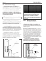
Page 17
Gas Supply
Inlet
Tee
Fitting
3 in.
(76mm) Min.
Cap
Nipple
To Equipment
Inlet
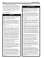
Figure 8. Typical design for a sediment
trap/drip leg.
RESIDENTIAL BOILERS
Brute-Mini
®
2. Check the gas supply to be sure that it is the same
as the gas indicated on the boiler’s plate. This boiler,
as shipped from the factory, is certied to operate
within the altitude range indicated on the rating plate.
If a eld conversion to a dierent altitude range or
dierent gas should be necessary, conversion parts
are available.
See Section 12.C on page 50 for part numbers.
3. Use the gures in Table 4 to size the gas inlet piping
from the gas meter to the heater. Check all local
codes for compliance before installing the heater.
4. A sediment trap (drip leg) must be installed ahead
of the gas controls (see Figure 8). Fit the trap with
a threaded cap which can be removed for cleaning.
5. Install a manual gas shuto valve for service and
safety. Do not use a restrictive gas cock. Flexible
gas connectors, if used, must be CSA rated for the
total input rating of the boiler.
6. Disconnect the boiler and its individual shuto
valve from the gas supply system during pressure
testing of the system at pressures higher than 1/2
pounds per square inch (psi) (3.45 kilopascals
[kPa]). If the test pressure is equal to or less than
1/2 psi (3.45 kPa), close the manual shuto valve
on the heater during the pressure test.
7. If the gas supply pressure is less than required,
check for undersized pipe between the meter and
the boiler, a restrictive tting, or an undersized
gas meter. Gas supply pressures to the heater are
listed in Table 3 on page 17.
SECTION 4 Gas Connections
4.A Gas Supply and Piping
1. Gas piping installation must be in accordance
with the latest edition of ANSI Z223.1 and all local
codes. In Canada, the installation must be in
accordance with CSA-B149.1 and all local codes
that apply.
CAUTION
Permanent damage to the gas valve will occur if the
following procedures are not followed.
ATTENTION
Vous endommagerez la soupape de gaz si vous ne
respectez pas les procédures suivantes.
NOTE: The maximum inlet gas pressure must not
exceed the specied value. The minimum value
listed is for the purpose of input adjustment. Refer
to Table 4
Table 3. Gas Supply Pressure Requirements
Supply Pressure Minimum Maximum
Natural Gas
5.5 Inches WC 10.5 Inches WC
(1.3 kPa) (2.5 kPa)
LP Gas
10.0 Inches WC 13.0 Inches WC
(2.4 kPa) (3.1 kPa)
Table 4. Gas Pipe Size Requirements*
Boiler Size
50 75 100 125 150 200
Needed Pipe Size
0-50ft
0-15m
1/2 3/4 3/4 3/4 3/4 1
50-100ft
15-30m
1/2 3/4 3/4 1 1 1-1/4
100-200ft
30-60m
3/4 1 1 1 1-1/4 1-1/4
*Note: These gures are for Natural Gas (.65 Sp. Gr.),
and are based on 1/2" water column pressure drop.
For LP (1.5 Sp. 11” wc) and 1/2” water column drop.
Check supply pressure with a manometer, and local code
requirements for variations. Pipe ttings must be consid-
ered when determining gas pipe size. See National Fuel
Gas Code or local code requirements for complete pipe
sizing requirements.
Equivalent
Distance
From Gas
Meter
1/2”1/2”
1/2”
1/2”
1/2”
1/2” 3/4” 3/4”
3/4”3/4” 3/4”
3/4”
3/4”3/4”
3/4” 1” 1”
1”
continued on next page.

Page 18
BRADFORD WHITE
NOTE: The boiler and all other gas
appliances sharing the boiler gas supply
line must be ring at maximum capacity to
properly measure the inlet supply pressure.
Low gas pressure could be an indication of
an undersize gas meter and/or obstructed
gas supply line.
8. The correct manifold gas pressure is stamped
on the rating plate. The regulator is pre-set at
the factory, and normally requires no further
adjustment.
9. Before operating the boiler, the complete gas
supply system and all connections must be
tested for leaks using approved methods for the
authority having jurisdiction. Do not use an open
ame.
CAUTION
Some leak test solutions (including soap and
water) may cause corrosion or stress cracking.
Rinse the piping with water after testing.
ATTENTION
Certaines solultions d’essai d’étanchéité (y
compris l’eau et le savon) peuvent causer de
la corrosion ou de la ssuration. Rincez les
tuyaux à l’eau apprès l’essai d’étanchéité.
WARNING
The boiler is designed for use with either natural
gas or LP gas, but only ships from the factory as
natural gas. Conversion kits are available. DO
NOT ATTEMPT TO CONVERT THIS HEATER
FOR USE WITH ANY OTHER TYPE OF FUEL.
AVERTISSEMENT
Le unit est conçu pour être utilisé avec du gaz
naturel ou du gaz LP, mais seulement des
navires de l’usine comme gaz naturel. Des
kits de conversion sont disponibles. NE PAS
ESSAYER DE CONVERTIR CET APPAREIL À
UN AUTRE TYPE DE GAZ.
4.B LP Gas Conversion
A conversion kit is available to convert this boiler for
operation on LP Gas. The boiler’s existing gas valve
is converted by changing the valve’s outlet regulator
spring and resetting the outlet pressure regulator.
See Section 12.C on page 50 for kit part numbers.
The Gas Conversion Kit includes the following:
1. Gas valve regulator spring
2. Main Burner and Pilot Orices
3. Installation Instructions
4. Conversion Label
4.C Special Precautions for LP Gas
LP Gas is heavier than air and can therefore more
readily collect or “pool” in enclosed areas if provision
for proper ventilation is not made. Be sure to pay
special attention to proper ventilation for LP gas.
Locate boilers a safe distance from LP gas cylinders
and lling equipment. In the United States, consult
the “National Fuel Gas Code” ( NFPA 54 / ANSI
Z223.1, latest edition ) or in Canada, the Propane
Installation Code ( CSA-B149.2 ), any local codes and
re protection authorities about specic installation
restrictions in your area.

Page 19
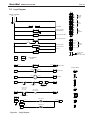
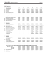
Table 5. Water Flow Requirements and Temperature Rise
Water Flow Requirements
Electrical
Data
All Sizes
with
Low Loss Header without Low Loss Header
Voltage 120 V 120 V
FLA .70 A .20 A
MCA .9 A .25 A
MOP 15 A 15 A
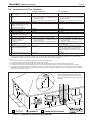
Minimum Clearances
Left + Right Sides Front Flue and Rear Top
Size inches cm inches cm inches cm inches cm
ALL 4 10 2 5 6 15 20 51
Minimum
Clearances
from
Adjacent
Construction
Temperature Rise
15°F 8°C 20°F 11°C 25°F 14°C
Size Flow Rate Headloss Flow Rate Headloss Flow Rate Headloss
gpm l/s ft m gpm l/s ft m gpm l/s ft m
50 5.3 0.3 0.3 0.1 4.0 0.3 0.2 0.1 3.2 0.2 0.1 0.1
75 8.0 0.5 0.6 0.2 6.0 0.4 0.3 0.1 4.8 0.3 0.2 0.1
100 10.7 0.7 1.3 0.4 8.0 0.5 0.7 0.2 6.4 0.4 0.5 0.2
125
*
13.3 0.8 2.2 0.7 10.0 0.6 1.3 0.4 8.0 0.5 0.8 0.2
150
*
17.0 1.1 2.5 0.8 12.8 0.8 1.8 0.5 10.3 0.6 1.2 0.4
200
*
22.8 1.4 5.0 1.5 17.0 1.0 3.1 0.9 13.7 0.9 1.9 0.6
*Models 125-200 ship with a low loss header with integral pump, so a separate boiler pump does not need to be sized or eld-supplied.
NOTES:
1. Shaded area represents typical temperature rise.
2. gpm = water ow in gallons per minute.
3. l/s = water ow in liters per second.
4. ft = pressure drop (headloss) through the boiler in feet of water.
5. m = pressure drop (headloss) through the boiler in meters of water.
Sizing
Data
Heating Capacity AFUE % Water Gas
Input Nat Gas Conn. Conn.
Size MBTU/h kW MBTU/h kW % in. in.
50 50 14.7 42 12.6 84 1-1/4 3/4
75 75 22.0 63 18.8 84 1-1/4 3/4
100 100 29.3 84 24.9 84 1-1/4 3/4
125 125 36.6 105 31.1 84 1-1/4 3/4
150 150 44.0 126 37.2 84 1-1/4 3/4
200 199 58.3 168 49.2 84 1-1/4 3/4
SECTION 5 PUMP REQUIREMENTS
5.A Pump Sizing
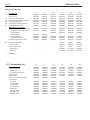
Table 6. Equivalent Feet and Head Loss
Model
Size
GPM
Equivalent Feet
of ¾” Type M
Copper
Feet of Head
Loss
50 5
75 4.9
100 6.5
75 7.5
75 10.3
100 13.8
100 10
75 17.6
100 23.5
RESIDENTIAL BOILERS
Brute-Mini
®
This boiler has a water tube design, and requires
correct water ow for proper operation and long life.
Models 125-200 are built with a low loss header with
integral pump that serves the boiler and ensures proper
water ow. Optional low loss header with integral pump
kits, or kits with just pumps, are oered for use with
models 50, 75 and 100. When neither of the optional
kits are used with models 50, 75 and 100, care must be
taken to choose pumps and in the design of the piping.
A typical residential pump can ow enough water for the
average, properly-designed, zone system for models 50
and 75. If a zone exceeds 100 equivalent feet of 3/4”
pipe, a pump may not be large enough to overcome the
resistance and ensure proper water ow through the
boiler.
To size the pump use the total equivalent pipe length
to nd its headloss and add it to the boiler headloss in
Table 6. Use pump curves for pump selection. Primary/
Secondary piping is another option to reduce the need
to use larger pumps.
.
For boilers with the LLH system the boiler will
maintain the proper ow through the boiler
regardless of the ow through the system. This
means that the system ow is now only critical to
the building comfort not the boiler safety. Headloss
is only calculated through the individual zones for
sizing of the system pump(s).

Page 20
SECTION 6 WATER
CONNECTIONS
6.A Water Piping
NOTE: This boiler must be installed in a closed
pressure system with a minimum of 12 psi (82.7kPa)
static pressure at the boiler.
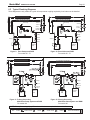
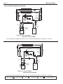
Section 6.F on page 21 shows ‘typical’ plumbing
installations. Be sure to provide unions and isolation
valves at the boiler inlet and outlet so it can be isolated
for service. Check local codes for specic plumbing
requirements before beginning the installation.
An ASME pressure relief valve is supplied on all JX
boilers, and is pre-set at 30 PSI. The valve outlet
piping should be discharged to a drain and must be
piped to discharge near the oor. It cannot have a
threaded end at its termination point nor be of a closed
circuit design.
A pressure reducing valve (automatic feed) must
be used to maintain the system at constant proper
pressure. Supply properly installed purge valves to
eliminate air from each circuit.
A drain valve is supplied with the boiler. This valve is
installed on the lower right side of the boiler and is
used for draining the unit for service. If the boiler is
being drained so that it will be left in a space that may
freeze, it is critical to remove the two lower plugs from
the left side of the heat exchanger. See Section 9.E on
page 40 This is the only way to ensure all the water
is out of the heat exchanger.
Be sure at least one air elimination device is installed
in the system to eliminate trapped air from the system.
Hot water piping should be supported by suitable
hangers or oor stands, NOT by the boiler. Due
to expansion and contraction of copper pipe,
consideration should be given to the type of hangers
used. Rigid hangers could transmit noise through the
system caused by the piping sliding in the hangers.
Gas piping shall also be supported by suitable hangers
or oor stands, not the boiler.
A properly sized expansion tank must be included in
the system.
6.B Low Loss Header with Integral Pump
Models 125-200 are provided with a Low Loss Header
to ensure that the boiler always receives adequate
water ow for optimum eciency, ease of installation
and long life. The Low Loss Header, with its integral
Boiler Pump, eliminates the need for by-pass piping
because it allows the system ow and the boiler ow
to be independent of each other without the cost
and complexity of a typical Primary / Secondary type
system. See Section 6.F
6.C Chilled Water Systems
If the boiler is installed in conjunction with refrigeration
systems, it shall be installed so that the chilled
medium is piped in parallel with the heating boiler with
appropriate valves to prevent the chilled medium from
entering the heating boiler.
When boiler piping is connected to heating coils, which
are in close proximity to refrigerated air circulation, there
must be ow control valves or other automatic methods
to prevent gravity circulation of the boiler water during
the cooling cycle.
6.D Oxygen Permeable Systems
This boiler must not be directly connected to a heating
system utilizing oxygen permeable tubing. Provide a
water-to-water heat exchanger between systems to
prevent corrosion of ferrous metals such as the boiler’s
piping, wet walls, etc. Air elimination devices are not
sucient protection and corrosion damage is not
covered under the limited warranty.
6.E Anti-freeze
Non-toxic HVAC anti-freeze may be added to the
hydronic system provided the concentration does not
exceed 50%, and the anti-freeze contains an anti-
foammant and rust inhibitor. Follow the anti-freeze
manufacturer’s recommendations for yearly or biannual
replacement of system anti-freeze. Never use toxic
automotive anti-freeze in a boiler system.
NOTE: Manufacturer supplied pumps are not all
capable of maintaining the reduced temperature rise
required with glycol concentrations greater than 35%.
If glycol concentrations required are greater than 35%
a eld supplied pump should be used.
CAUTION
Dierent glycol products may provide varying degrees
of protection. Glycol products must be maintained
properly in a heating system, or they may become
ineective. Consult the glycol specications, or
the glycol company, for information about specic
products, maintenance of solutions, and set up
according to your particular conditions.
The Low Loss Header is available for the model 50,
75, and 100 as an option for smaller systems that
could benet from its use.
BRADFORD WHITE
La page est en cours de chargement...
La page est en cours de chargement...
La page est en cours de chargement...
La page est en cours de chargement...
La page est en cours de chargement...
La page est en cours de chargement...
La page est en cours de chargement...
La page est en cours de chargement...
La page est en cours de chargement...
La page est en cours de chargement...
La page est en cours de chargement...
La page est en cours de chargement...
La page est en cours de chargement...
La page est en cours de chargement...
La page est en cours de chargement...
La page est en cours de chargement...
La page est en cours de chargement...
La page est en cours de chargement...
La page est en cours de chargement...
La page est en cours de chargement...
La page est en cours de chargement...
La page est en cours de chargement...
La page est en cours de chargement...
La page est en cours de chargement...
La page est en cours de chargement...
La page est en cours de chargement...
La page est en cours de chargement...
La page est en cours de chargement...
La page est en cours de chargement...
La page est en cours de chargement...
La page est en cours de chargement...
La page est en cours de chargement...
-
 1
1
-
 2
2
-
 3
3
-
 4
4
-
 5
5
-
 6
6
-
 7
7
-
 8
8
-
 9
9
-
 10
10
-
 11
11
-
 12
12
-
 13
13
-
 14
14
-
 15
15
-
 16
16
-
 17
17
-
 18
18
-
 19
19
-
 20
20
-
 21
21
-
 22
22
-
 23
23
-
 24
24
-
 25
25
-
 26
26
-
 27
27
-
 28
28
-
 29
29
-
 30
30
-
 31
31
-
 32
32
-
 33
33
-
 34
34
-
 35
35
-
 36
36
-
 37
37
-
 38
38
-
 39
39
-
 40
40
-
 41
41
-
 42
42
-
 43
43
-
 44
44
-
 45
45
-
 46
46
-
 47
47
-
 48
48
-
 49
49
-
 50
50
-
 51
51
-
 52
52


Bradford White BJX075 Manuel utilisateur
- Taper
- Manuel utilisateur
dans d''autres langues
- English: Bradford White BJX075 User manual
Documents connexes
Autres documents
-
Bryant BWH Le manuel du propriétaire
-
Crown Boiler Cast Iron Manuel utilisateur
-
Laars Mini-Therm JX Residential Gas-Fired Hydronic Boilers Manuel utilisateur
-
FIELD CONTROLS GVD-4 thru -12 Gas Vent Damper Guide d'installation
-
U.S. Boiler Company 303BNI-T Mode d'emploi
-
Ashley Hearth Products AGDV20L Guide d'installation
-
Raypak 1005-2005 Information Manual
-
Peerless Boilers 63 series Manuel utilisateur
-
U.S. Boiler Company ES28BPI-T Mode d'emploi
-