
SCP 011
S-DIAS Safety CPU Module
Date of creation: 18.12.2013
Version date: 28.02.2020
Article number: 20-890-011-E

Publisher: SIGMATEK GmbH & Co KG
A-5112 Lamprechtshausen
Tel.: +43/6274/4321
Fax: +43/6274/4321-18
Email: [email protected]
WWW.SIGMATEK-AUTOMATION.COM
Copyright © 2013
SIGMATEK GmbH & Co KG
Translation from German
All rights reserved. No part of this work may be reproduced, edited using an electronic system, duplicated or
distributed in any form (print, photocopy, microfilm or in any other process) without the express permission.
We reserve the right to make changes in the content without notice. The SIGMATEK GmbH & Co KG is not
responsible for technical or printing errors in the handbook and assumes no responsibility for damages that occur
through use of this handbook.

S-DIAS SAFETY CPU MODULE SCP 011
28.02.2020 Page 1
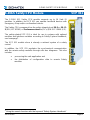
S-DIAS Safety CPU Module SCP 011
The S-DIAS 011 Safety CPU module supports up to 16 Safe IO
modules. In addition, the SCP 011 can operate handheld devices with
Emergency Stop and/or confirmation buttons.
The Safety CPU component has the safety integrity level SIL3 or SIL CL
3 (EN / IEC 62061) or Performancelevel e (PL e) (EN ISO 13849-1/-2).
The safety-related SCP 011 is ideal for use in systems with optional
modules and interface variables according to Safety System Handbook,
see homepage
1
.
The SCP 011 module alone is already a minimal system of a safety
control.
In addition, the SCP 011 regulates the synchronized communication
with the remote safety modules through safe bus telegrams. This also
includes
• processing the safe application and
• the distribution of configuration data to remote Safety
modules
1
Using the search function with the keyword “Safety System Handbook”

SCP 011 S-DIAS SAFETY CPU MODULE
Page 2 28.02.2020
Contents
1 Basic Safety Guidelines ......................................................... 4
1.1 General Information on Safety .................................................... 4
1.2 Further Safety Guidelines ............................................................ 5
1.3 General Requirements ................................................................. 6
2 Safety Conformity ..................................................................10
2.1 Functional Safety Standards ..................................................... 10
2.2 EU Conformity Declaration ........................................................ 10
2.3 Safety-Relevant Parameters ...................................................... 10
2.4 Compatibility ............................................................................... 11
3 Technical Data .......................................................................12
3.1 Performance Data ....................................................................... 12
3.2 Electrical Requirements ............................................................. 12
3.2.1 Module Supply (Input) ....................................................................... 12
3.2.2 S-DIAS Bus/Safety Supply (Output) .................................................. 13
3.3 Miscellaneous ............................................................................. 16
3.4 Environmental Conditions ......................................................... 16
4 Mechanical Dimensions ........................................................17
5 Connector Layout ..................................................................18
5.1 Status LEDs ................................................................................. 19
5.2 Applicable Connectors ............................................................... 20
5.3 Label Field ................................................................................... 21

S-DIAS SAFETY CPU MODULE SCP 011
28.02.2020 Page 3
6 Validation Button ................................................................... 22
6.1 Explanation of the Individual Sequences ................................. 22
6.1.1 Start Sequence ................................................................................. 22
6.1.2 Command Selection Sequence ......................................................... 23
6.1.3 End Sequence .................................................................................. 23
6.1.4 Error Sequence ................................................................................. 24
6.2 Overview of Commands ............................................................. 25
6.3 Overview of Module Statuses and Commands ........................ 25
6.4 Handling the microSD Card ....................................................... 27
6.5 Configuring a Safety CPU with the SD Card ............................ 28
7 Error Response ..................................................................... 30
7.1 Restart Errors .............................................................................. 30
7.2 Configuration Distribution Error ............................................... 31
7.3 Troubleshooting .......................................................................... 32
7.4 Troubleshooting with the SafetyDesigner ............................... 32
7.5 Correcting a Wiring Error ........................................................... 32
8 Wiring Guidelines .................................................................. 33
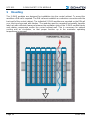
9 Mounting ................................................................................ 34
10 Supported Cycle Times ........................................................ 36
10.1 Cycle Times below 1 ms (in µs) ................................................. 36
10.2 Cycle Times equal to or higher than 1 ms (in ms) ................... 36
11 Disposal ................................................................................. 36

SCP 011 S-DIAS SAFETY CPU MODULE
Page 4 28.02.2020
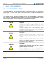
1 Basic Safety Guidelines
1.1 General Information on Safety
If the safety guidelines are not followed, dangers to personnel can arise that could lead to
serious injury or in worst cases, death. In less serious cases, systems and equipment can
be damaged.
The following symbols identify the individual risks as well as the degree of seriousness;
their respective meanings are briefly explained. You should therefore familiarize yourself
with the safety symbols and their meanings to prevent dangers and risks.
DANGER!
DANGER!
Identifies an immediate danger with high risk, which
can lead to immediate death or serious injury if not
avoided.
Indique un danger direct à haut risque d’un décès
immédiat ou des blessures graves si les consignes de
sécurité ne sont pas respectées.
WARNING
WARNING
Identifies a possible danger with a mid-level risk,
which can lead to death or (serious) injury if not
avoided.
Indique un danger possible d’un risque moyen de
décès ou de (graves) blessures si les consignes de
sécurité ne sont pas respectées.
CAUTION!
CAUTION!
Identifies a low risk danger, which can lead to injury or
property damage if not avoided.
Indique un danger avec un niveau de risque faible des
blessures légères ou des dommages matériels si les
consignes de sécurité ne sont pas respectées.

S-DIAS SAFETY CPU MODULE SCP 011
28.02.2020 Page 5
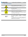
1.2 Further Safety Guidelines
Warning, dangerous electrical voltage
Avertissement d’une tension électrique dangereuse
Hot surface warning
Avertissement d’une surface chaude
Danger for ESD-sensitive components
Les signes de danger pour les composants sensibles
aux décharges électrostatiques
This symbol identifies important or additional
information regarding the operation of the safety
modules.
Ce symbole indique des informations importantes ou
supplémentaires concernant le fonctionnement des
modules de sécurité particuliers.

SCP 011 S-DIAS SAFETY CPU MODULE
Page 6 28.02.2020
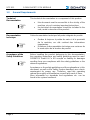
1.3 General Requirements
Technical
Documentation
This technical documentation is a component of this product.
• this document must be accessible in the vicinity of the
machine, since it contains important instructions.
• the technical documentation should be included in the
sale, rental or transfer of the product.
Documentation
technique
Cette documentation technique fait partie intégrale du produit.
• Gardez la toujours à portée de main et à la proximité
de la machine, car elle contient des informations
importantes.
• Distribuez la documentation technique aux secteurs de
la vente et/ou de la location du produit.
Acceptance of the
Safety Guidelines
Before handling the product belonging to this documentation,
the operating instructions and safety guidelines must be read.
SIGMATEK GmbH & Co KG accepts no liability for damages
resulting from non-compliance with the safety guidelines or the
relevant regulations.
Acceptance or the safety guidelines and the explanations in this
document, as well as the Safety System handbook are a basic
requirement for proper use. Therefore, read this operating
manual thoroughly and familiarize yourself with each of them.
More information on standards and regulations etc. can be
found in the system handbook.

S-DIAS SAFETY CPU MODULE SCP 011
28.02.2020 Page 7
Prendre connaissance
de consignes de
sécurité
Avant toute manipulation on doit impérativement prendre
connaissance de consignes de sécurité et du mode d’emploi.
SIGMATEK GmbH & Co KG n'assume aucune responsabilité
pour les dommages causés par le non-respect des consignes
de sécurité ou du mode d’emploi respectif.
La connaissance de consignes de sécurité et le contenu de
cette documentation ainsi que le mode d’emploi du système de
sécurité constitue une condition préalable à l'utilisation prévue.
Lisez ce mode d’emploi et assurez-vous de le comprendre
jusqu’aux détails.
Pour plus d'informations sur les normes et les lignes directrices,
etc., reportez-vous au mode d’emploi.
Qualified Personnel
Installation, assembly, programming and initial start-up,
operation, maintenance and decommissioning of control and
automation technology products in general, as well as safety-
related products especially, can only be performed by qualified
personnel.
Qualified personnel in this context are people, who have
completed training or have trained under supervision of
qualified personnel and have been authorized to operate and
maintain safety-related equipment, systems and facilities in
compliance with the strict guidelines and standards of safety
technology.
Personnel qualifié
Installation, montage, programmation, mise en service,
l'exploitation, l'entretien et mise hors service de produits de
commande et d'automatisation en général, et de produits liés à
la sécurité, en particulier, ne peut être effectuée que par le
personnel qualifié.
On entend sous terme personnel qualifié les personnes ayant
acquis une formation professionnelle dispensé par un
spécialiste sur l’utilisation et surveillance des composants et
des systèmes de sécurité, ceci conformément aux lignes
directrices et les normes en vigueur.

SCP 011 S-DIAS SAFETY CPU MODULE
Page 8 28.02.2020
Designated Use
The Safety modules are designed for use in safety-oriented
applications and meet the required conditions for safety
operation in compliance with Performance level e (PL e), in
accordance with EN ISO 13849-1/-2 and SIL3 or SIL CL 3 in
accordance with EN 62061.
For your own safety and the safety of others, use safety
modules for their designated purpose. Correct EMC installation
as well as proper transport and storage are also included in
designated use.
Non-designated use consists of
• Any change made to the safety modules of any kind.
• The use of damaged safety modules.
• The use of the safety module outside of the
instructions described in this handbook.
• The use of the safety module outside of the technical
data described in this handbook.
Utilisation prévue
Les modules de sécurité sont conçus pour une utilisation dans
les applications sollicitant un niveau de sécurité et répondent à
toutes les conditions nécessaires pour un fonctionnement sûr
conformément au niveau de performance e (PL e) selon la
norme EN ISO 13849-1/-2 et SIL3 ou SIL CL 3 de la norme EN
62061.
Utilisez le module de sécurité conformément à son mode
d’emploi pour votre propre sécurité et celle d'autres personnes.
L'utilisation conforme comprend également une installation
conforme CEM ainsi que le transport et le stockage conforme.
L'utilisation abusive comprend entre autres:
• Les modifications quelconques apportées aux modules
de sécurité.
• Utilisation de modules de sécurité endommagés.
• Utilisation de modules de sécurité en dehors du cadre
décrit dans ce mode d’emploi.
• Utilisation de modules de sécurité en dehors des
spécifications décrites dans ce mode d’emploi.

S-DIAS SAFETY CPU MODULE SCP 011
28.02.2020 Page 9
Operator Due Diligence
The operator must ensure that
• The Safety modules are to be used for their
designated purpose only.
• The Safety modules are to be operated in error-free,
fully functional condition only.
• Only sufficiently qualified and authorized personnel my
operated the Safety modules.
The documentation is complete and in readable condition and
available at the site of operation.
Obligation de diligence
L’utilisateur doit s'assurer que
• les modules de sécurité ne sont utilisés que selon les
spécifications.
• uniquement les modules de sécurité en parfait état de
fonctionnement peuvent être utilisés.
• seulement le personnel qualifié et autorisé puisse
manipuler les modules de sécurité.
la documentation dans son intégralité et dans un état lisible est
mise à disposition à l’endroit où les modules de sécurité sont
utilisés.

SCP 011 S-DIAS SAFETY CPU MODULE
Page 10 28.02.2020
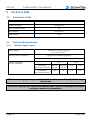
2 Safety Conformity
2.1 Functional Safety Standards
- EN / IEC 62061:2005/A2 2015
- EN ISO 13849-1:2015
- EN ISO 13849-2:2012
2.2 EU Conformity Declaration
CE Declaration of Conformity
The SCP 011 complies with the following European directives:
• 2006/42/EG “Directive of the European Parliament and of the
Council of 17 May 2006 on Machinery and Change to the Directive
95/16/EC” (machine guideline)
• 2014/30/EU “Electromagnetic Compatibility” (EMC guideline)
• 2011/65/EU Restricted use of certain hazardous substances in
electrical and electronic equipment (RoHS Guideline)
The EU Conformity Declarations are provided on the SIGMATEK website.
Using the search function with the keyword “EU Declaration of Conformity”.
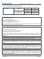
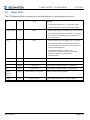
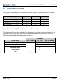
2.3 Safety-Relevant Parameters
CPU Module
Safety Parameters
Safety Levels
SCP 011
PFH
D
= 1,43E-10 (1/h)
MTTF
D
= 2689 years
DC = 99,00 %
SFF = 99,95 %
SIL 3
according to EN/IEC 62061
PL e / Cat. 4
according to EN ISO 13849-1/-2
Structure: Two-channel redundant (diverse)

S-DIAS SAFETY CPU MODULE SCP 011
28.02.2020 Page 11
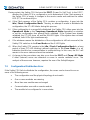
2.4 Compatibility
The safety-related module SCP 011 is supported with firmware version V334 and build No.
1156 or higher of the Safety Designer.
Use of Safe Analog Values (SAFEDINT):
If Safe analog values (variables of type SAFEDINT) are transferred and further processed,
an SCP011 with Firmware version V344 or higher MUST be used (HW version 1.60).
SAFEDINT variables are transferred when for two or more Safety CPU's in a project,
SAFEDINT values are placed in the networks of the remote Safety CPU or with the use of
SAFEDINT values in interface frames (safe variables).
Compatibility
For compatibility of the S-DIAS Safety modules, see section
"Compatibility of S-DIAS Safety Modules" in the system
handbook.

SCP 011 S-DIAS SAFETY CPU MODULE
Page 12 28.02.2020
3 Technical Data
3.1 Performance Data
Interfaces
1x Safety Interface
Program interfaces
1x USB device
Bus connection possible
yes
Miscellaneous
microSD slot
Supply voltage
+24 V
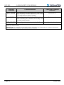
3.2 Electrical Requirements
3.2.1 Module Supply (Input)
Supply voltage
+18-30 V DC, typically +24 V DC
UL: Class 2 or LVLC
(1)
Current, internal consumption
typically 90 mA internal consumption
maximum 1.4 A
(2) (3)
Current consumption
from the S-DIAS bus
+5 V
+24 V
with missing
+24 V connection (X3)
typically
170 mA
maximum
200 mA
0 A
0 A
with existing
+24 V connection (X3)
0 A
0 A
0 A
0 A
A fuse for the supply voltage must be installed, which can sufficiently limit voltage
and current.
Un fusible conforme aux limites de la tension et du courant d'alimentation doit être
présent en amont de l'alimentation.

S-DIAS SAFETY CPU MODULE SCP 011
28.02.2020 Page 13
3.2.2 S-DIAS Bus/Safety Supply (Output)
Voltage supply
in the
S-DIAS bus
+5 V
+24 V
0 A
0 A
in the
S-DIAS Safety bus
(supply of the I/O modules)
+12 V
+24 V
max. 0.8 A
(2) (4)
max. 0.8 A
(2) (4)
______________
(1)
For USA and Canada:
The supply must be limited to:
a) max. 5 A at voltages from 0-20 V DC, or
b) 100 W at voltages from 20-60 V DC
The limiting component (e.g. transformer, power supply or fuse) must be certified by an
NRTL (Nationally Recognized Testing Laboratory).
(1)
Pour les États-Unis et le Canada:
L’alimentation doit être limitée à:
a) max. 5 A pour des tensions de 0-20 V DC, ou
b) 100 W pour des tensions de 20-60 V DC
Le composant imposant la limite (par exemple, transformateur, alimentation électrique ou
fusible) doit être certifié par un NRTL (National Recognized Testing Laboratory, par
exemple, UL).
(2)
dependent on the number of connected modules on the S-DIAS Safety bus
(3)
For loading the internal capacitors a higher power consumption can occur for a short time
(microseconds). This value depends on the input voltage and the impedance of the supply
source.
(4)
If this S-DIAS Safety CPU module is connected to several modules, the total currents for
+24 V and +12 V must be calculated based on the module documentations of the used S-
DIAS Safety modules! The total current of the +24 V supply must not exceed 800 mA. The
total current of the +12 V supply must not exceed 800 mA.
(4)
Si ce module S-DIAS Safety est connecté à un SCP avec plusieurs modules S-DIAS, le
courant total des modules utilisés doit être défini et contrôlé. Le courant total de
l'alimentation +24 V ne peut pas dépasser 800 mA! Le courant total de l'alimentation +12 V
ne peut pas dépasser 800 mA!

SCP 011 S-DIAS SAFETY CPU MODULE
Page 14 28.02.2020
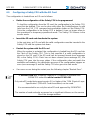
If the SCP 011 with a firmware version lower than V355 resp. with a Safety number
lower than S01.03.01 is integrated with Safety I/O modules in the S-DIAS system (blue
moduls), the voltage increase of the +24 V supply of the SCP 011 must not happen
later than 100 msec after the voltage supply oft he S-DIAS supply moduls, otherwise
it can happen, that the SCP 011 does not recognize the Safety I/O moduls on the
Safety bus. This results in a Safety error (error code 1009, reason code 15 in the
Safety Designer) and thus the Safety application is not started.

S-DIAS SAFETY CPU MODULE SCP 011
28.02.2020 Page 15

SCP 011 S-DIAS SAFETY CPU MODULE
Page 16 28.02.2020
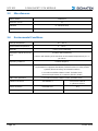
3.3 Miscellaneous
Article number
20-890-011
Hardware version
1.x
Standard
UL 508 (E247993)
Approbations
UL, cUL, CE
3.4 Environmental Conditions
Storage temperature
-20 ... +85 °C
Environmental temperature
0 ... +55 °C
Humidity
0-95 %, non-condensing
Installation altitude above sea
level
0-2000 m without derating
> 2000 m with derating of the maximum environmental temperature by 0.5 °C
per 100 m
Operating conditions
Pollution degree 2
EMC resistance
in accordance with 61000-6-7:2015 (Generic standards - Immunity
requirements for equipment intended to perform functions in safety-related
systems (functional safety) at industrial locations)
in accordance with EN 61000-6-2:2007 (industrial area)
(increased requirements in accordance with IEC 62061)
EMC noise generation
in accordance with EN 61000-6-4:2007 (industrial area)
Vibration resistance
EN 60068-2-6
3.5 mm from 5-8.4 Hz
1 g from 8.4-150 Hz
Shock resistance
EN 60068-2-27
15 g
Protection type
EN 60529
IP20

S-DIAS SAFETY CPU MODULE SCP 011
28.02.2020 Page 17
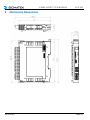
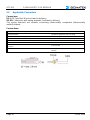
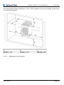
4 Mechanical Dimensions

SCP 011 S-DIAS SAFETY CPU MODULE
Page 18 28.02.2020
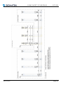
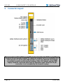
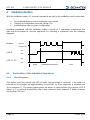
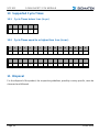
5 Connector Layout
The connections of the +24 V supply (X3: pin 1 and pin 2) or the GND supply (X3: pin
3 and pin 4) are internally bridged. To supply the module, only one connection to a
+24 V pin (pin 1 or pin 2) and a GND pin (pin 3 or pin 4) is required. The bridged
connections may be used for further looping of the +24 V supply and the GND
supply. However, it must be taken into account that a total current of 6 A per
connection is not exceeded by the forward looping!
La page est en cours de chargement...
La page est en cours de chargement...
La page est en cours de chargement...
La page est en cours de chargement...
La page est en cours de chargement...
La page est en cours de chargement...
La page est en cours de chargement...
La page est en cours de chargement...
La page est en cours de chargement...
La page est en cours de chargement...
La page est en cours de chargement...
La page est en cours de chargement...
La page est en cours de chargement...
La page est en cours de chargement...
La page est en cours de chargement...
La page est en cours de chargement...
La page est en cours de chargement...
La page est en cours de chargement...
La page est en cours de chargement...
La page est en cours de chargement...
-
 1
1
-
 2
2
-
 3
3
-
 4
4
-
 5
5
-
 6
6
-
 7
7
-
 8
8
-
 9
9
-
 10
10
-
 11
11
-
 12
12
-
 13
13
-
 14
14
-
 15
15
-
 16
16
-
 17
17
-
 18
18
-
 19
19
-
 20
20
-
 21
21
-
 22
22
-
 23
23
-
 24
24
-
 25
25
-
 26
26
-
 27
27
-
 28
28
-
 29
29
-
 30
30
-
 31
31
-
 32
32
-
 33
33
-
 34
34
-
 35
35
-
 36
36
-
 37
37
-
 38
38
-
 39
39
-
 40
40


SIGMATEK S-DIAS SCP 111 Manuel utilisateur
- Taper
- Manuel utilisateur
- Ce manuel convient également à
dans d''autres langues
- English: SIGMATEK S-DIAS SCP 111 User manual
Documents connexes
Autres documents
-
Philips PSP 1000 Mode d'emploi
-
Check Point 61000 Getting Started Manual
-
Fujitsu Server M8000 Manuel utilisateur
-
Mellanox Technologies SwitchX Manuel utilisateur
-
Eurotech ReliaGATE 10-14 Le manuel du propriétaire
-
-
Mellanox Technologies MSX6036G-2SFS Manuel utilisateur
-
EVGA 220-G5-0850-X1 Manuel utilisateur
-
BE QUIET! Pure Power L8-600W Manuel utilisateur
-
BE QUIET! Pure Power L8-400W Fiche technique