
738Zplus Z-WAVE INTERFACE MODULE
Installation Guide
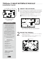
DESCRIPTION
1
SELECT THE LOCATION
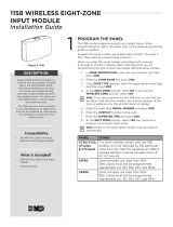
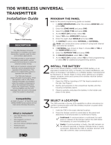
Select a central location for the 738Zplus Z-Wave Interface Module.
Keep in mind that at least one Z-Wave Plus device must be within
65 feet of the 738Zplus. Most Z-Wave Plus devices act as repeaters
for the signal to create longer and multiple transmission routes
(battery-powered Z-Wave Plus devices do not repeat signals in
order to extend battery life). See Figure 2.
Note: Place the module away from large, metal objects to
avoid interference with the Z-Wave Plus signal.
2
MOUNT THE 738Zplus
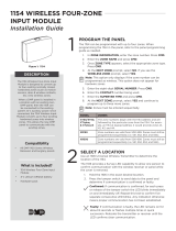
1. With the housing cover o, carefully remove the 738Zplus’s
PCB from the housing.
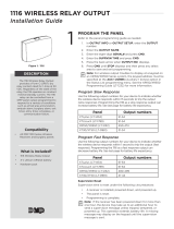
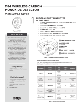
2. Use the supplied screws to secure the 738Zplus housing
against a wall or flat surface. See Figure 3.
The 738Zplus Z-Wave Interface
Module allows DMP panels to
communicate with up to 140
Z-Wave or Z-Wave Plus devices,
such as light controls, light bulbs,
door locks, garage door openers,
and thermostats.
The 738Zplus is automatically
recognized by DMP panels, and no
additional programming is required.
Once the 738Zplus is connected to
a DMP panel, users can immediately
begin adding Z-Wave devices to
their system.
Devices can be remotely controlled
from smart phones using the DMP
Virtual Keypad™ App.
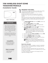
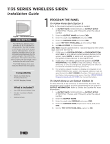
Figure 2: Example Z-Wave Plus Transmission Routes
= Z-Wave Plus Device
Oce
Dining
Living Room
Foyer
Kitchen
Garage
Control
Panel with
738Zplus
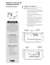
Figure 3: 738Zplus Housing with Mounting Holes
Mounting Holes
Figure 1: 738Zplus Z-Wave
Interface Module
Compatibility
• DMP XT30/XT50
Series panels
• DMP XR150/XR550
Series panels
• All Z-Wave and Z-Wave
Plus devices
• See the Compatibility section for
complete information.
What is Included?
• 738Zplus Z-Wave
Interface Module
• Hardware pack

2 738Zplus INSTALLATION GUIDE | DIGITAL MONITORING PRODUCTS
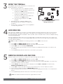
4
ADD DEVICES
After wiring the 738Zplus to the panel, use a DMP keypad to program Z-Wave Plus devices into the panel
through the User Menu Z-Wave Setup option. This allows users to add devices through the User Menu or
the Virtual Keypad™ app after installation. When possible, have the Z-Wave device near the 738Zplus during
setup and programming.
When programming Z-Wave devices into an XT30, XT50, or XTLplus panel with Version 171 or higher, you
can add multiple devices at once. If you add multiple devices at once, then you will name each device after
they have all been added.
Note: To add the 738Zplus to an existing network, use the LRN (Learn) function.
1. Press CMD until MENU? YES NO appears, then press YES.
2. Press CMD until ZWAVE SETUP? appears. Press any select key or area.
3. Select ADD. The screen displays PROCESSING.
4. When prompted, press the button (or series of buttons if adding a thermostat) on the device you
are adding.
5. The keypad displays that the device has connected to your system.
3
WIRE THE 738Zplus
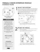
The 738Zplus has four wire connections to connect to the
panel’s keypad bus. See Figure 4.
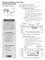
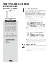
1. Connecting the wires to the 738Zplus terminals.
a. Connect the wire that delivers power to the
module to the RED terminal.
b. Connect the wire that sends data from the
module to the YEL terminal.
c. Connect the wire that receives data from
the panel to the GRN terminal.
d. Connect the ground wire to the BLK
terminal.
2. Carefully place the 738Zplus PCB back into
the housing, and then snap the housing cover
into place.
3. At the panel, connect the wires to the keypad bus
corresponding terminals.
Figure 4: 738Zplus Module
Wiring Connections
To Keypad Bus
REMOVE OR REPLACE DEVICES
If a device fails, users can remove or replace the device through the User Menu.
1. Press CMD until MENU? YES NO appears, then press YES.
2. Press CMD until ZWAVE SETUP? appears. Press any select key or area.
3. Select LIST and press CMD until the device you are removing or replacing displays. Then, press any
select key or area to select the device.
4. Select STATUS. The status of the device displays as either OKAY or FAILED. If the device fails,
REMOVE FAILED DEVICE displays.
5. Select YES to remove the device. Press the second select key or area to replace the device.
6. If you chose to replace the device, PROCESSING displays.
7. When prompted, press the button (or series of buttons if adding a thermostat) on the replacement
device.
8. The keypad displays that the device has connected to your system.
Note: The replacement device keeps the original device’s name.
5

738Zplus INSTALLATION GUIDE | DIGITAL MONITORING PRODUCTS 3
ADDITIONAL INFORMATION
LED Operation
The 738Zplus has three LEDs on the PCB that allow you to determine what type of operation is occurring. See Figure 4
for LED locations.
• PTX Green LED - If the light is blinking, then data is being sent to the panel.
• ZTX Green LED - If the light is blinking, then data is being sent to Z-Wave Plus devices.
• ZRX Yellow LED - If the light is blinking, then data is being received from Z-Wave Plus devices.
Z-Wave Terminology
Primary Controller: This is the main device used to set up and control your Z-Wave network. There can only be one
primary controller and it can be used to add or delete devices. A primary controller can be a portable device like a
hand-held remote, a static controller (permanently installed & never moved), a Z-Wave enabled PC or a Z-Wave enabled
Ethernet router/bridge.
Secondary Controller: The Z-Wave network supports multiple controllers so that additional Z-Wave remote controllers
can be used throughout the home. If the secondary controller is the same brand and model as the primary, it will have all
the same capabilities as the primary.
Home Control Network: The controllers and every Z-Wave device added with the primary controller are linked together
into a wireless network. Each device in the network has a unique address assigned to it and cannot be activated by a
neighbor’s Z-Wave controller.
Light/Node/Device: Node is the technical term used to describe a Z-Wave device in a home control network.
Please note that the terms “Node,” “Device,” and “Light” all refer to an individual Z-Wave enabled device and are
interchangeable within the context of these instructions.
Z-Wave Certification
• The 738Zplus is a Z-Wave Security enabled device.
• The 738Zplus can be added to an existing network as a secondary controller using the Learn (LRN) process.
• The 738Zplus is compatible with Z-Wave devices from all manufacturers.
• The 738Zplus can perform a Factory Default Reset by initializing defaults in the panel programming menu.
• The 738Zplus only supports group one with a maximum of one node.
• The 738Zplus takes no action when a basic set command is received.
Initialize Defaults
Only use this procedure when the Z-Wave network primary controller is missing or otherwise inoperable. Follow these
steps to initialize Z-Wave programming:
1. Reset the panel.
2. Enter 2313 (DIAG) at a keypad and press CMD to access the panel DIAGNOSTIC MENU.
3. Press CMD until INIT Z-WAVE displays and press a top row select key or area.
4. Select YES when Z-WAVE? NO YES displays. INIT SUCCESSFUL displays when all Z-Wave programming has been
initialized.
COMPATIBILITY
XT30/XT50 Series Panels
738Zplus modules connected to DMP XT30/XT50 Series panels with Version 171 firmware or higher provide full Z-Wave
Plus functionality. DMP XT30/XT50 Series panels with Version 125 or earlier provide standard Z-Wave functionality.
XR150/XR550 Series Panels
738Zplus modules connected to DMP XR150/XR550 Series panels with Version 182 firmware or higher provide full
Z-Wave Plus functionality. DMP XR150/XR550 Series panels with Version 181 or earlier provide standard Z-Wave
functionality.
Note: If you are upgrading firmware for an XT30/XT50 Series or an XR150/XR550 Series panel that is already
connected to a 738Zplus, you will need to initialize panel defaults to access Z-Wave Plus functionality. See the
appropriate panel Programming Guide for more information on initializing defaults.

Designed, engineered, and
manufactured in Springfield, Missouri
INTRUSION • FIRE • ACCESS • NETWORKS
2500 North Partnership Boulevard
Springfield, Missouri 65803-8877
800.641.4282 | DMP.com
Specifications
Power Requirements
Operating Voltage 8 to 14VDC
Current Draw 40mA
Frequency Range 908 MHz
Dimensions 4.5”W x 2.75”H x 1.75”D
Color White
Housing Material Flame retardant ABS
Certifications
FCC Part 15 ID: CCKPC0137R2
Industry Canada: 5251A-PC0137R2
738Zplus Z-WAVE
INTERFACE MODULE
© 2019 Digital Monitoring Products, Inc.
LT-1608 19111
FCC INFORMATION
This device complies with Part 15 of the FCC Rules. Operation is subject to the following two conditions:
1. This device may not cause harmful interference, and
2. This device must accept any interference received, including interference that may cause undesired operation.
The antenna used for this transmitter must be installed to provide a separation distance of at least 20 cm (7.874 in) from all persons. It
must not be located or operated in conjunction with any other antenna or transmitter.
Changes or modifications made by the user and not expressly approved by the party responsible for compliance could void the user’s
authority to operate the equipment.
Note: This equipment has been tested and found to comply with the limits for a Class B digital device, pursuant to part 15 of the
FCC Rules. These limits are designed to provide reasonable protection against harmful interference in a residential installation.
This equipment generates, uses and can radiate radio frequency energy and, if not installed and used in accordance with the
instructions, may cause harmful interference to radio communications. However, there is no guarantee that interference will not
occur in a particular installation. If this equipment does cause harmful interference to radio or television reception, which can be
determined by turning the equipment o and on, the user is encouraged to try to correct the interference by one or more of the
following measures:
• Reorient or relocate the receiving antenna.
• Increase the separation between the equipment and receiver.
• Connect the equipment into an outlet on a circuit dierent from that to which the receiver is connected.
• Consult the dealer or an experienced radio/TV technician for help.
Industry Canada Information
This device complies with Industry Canada Licence-exempt RSS standard(s). Operation is subject to the following two conditions:
1. This device may not cause interference, and
2. This device must accept any interference, including interference that may cause undesired operation of the device.
Le présent appareil est conforme aux CNR d’Industrie Canada applicables aux appareils radio exempts de licence. L’exploitation est
autorisée aux deux conditions suivantes : (1) l’appareil ne doit pas produire de brouillage, et (2) l’utilisateur de l’appareil doit accepter
tout brouillage radioélectrique subi, même si le brouillage est susceptible d’en compromettre le fonctionnement.
This system has been evaluated for RF Exposure per RSS-102 and is in compliance with the limits specified by Health Canada Safety
Code 6. The system must be installed at a minimum separation distance from the antenna to a general bystander of 7.87 inches (20 cm)
to maintain compliance with the General Population limits.
L’exposition aux radiofréquences de ce système a été évaluée selon la norme RSS-102 et est jugée conforme aux limites établies par le
Code de sécurité 6 de Santé Canada. Le système doit être installé à une distance minimale de 7.87 pouces (20 cm) séparant l’antenne
d’une personne présente en conformité avec les limites permises d’exposition du grand public.
-
 1
1
-
 2
2
-
 3
3
-
 4
4


Digital Monitoring Products LT 1608 Guide d'installation
- Taper
- Guide d'installation
- Ce manuel convient également à
dans d''autres langues
Documents connexes
-
 Digital Monitoring Products 763 WiFi Module Guide d'installation
-
 Digital Monitoring Products 1158 Manuel utilisateur
-
 Digital Monitoring Products 1116 Guide d'installation
-
 Digital Monitoring Products 263LTE Series Cellular Communicator Guide d'installation
-
 Digital Monitoring Products X1 SERIES SINGLE-DOOR AND MULTI-DOOR ACCESS CONTROLLER Compliance Guide
-
 Digital Monitoring Products 1158 Guide d'installation
-
 Digital Monitoring Products 1154 Wireless Four-zone Input Module Guide d'installation


Autres documents
-
 DMP 738Zplus Manuel utilisateur
-
 DMP Electronics 1116 Guide d'installation
-
 DMP Electronics 1135 Series Guide d'installation
-
 DMP Electronics 263LTE-V Guide d'installation
-
DMP 1117 Guide d'installation
-
 DMP Electronics 1158 Guide d'installation
-
 DMP Electronics 1101 Guide d'installation
-
 DMP Electronics 1106 Guide d'installation
-
 DMP 1184 Guide d'installation
-
OK. PTX-KIT1 Manuel utilisateur


