Digital Monitoring Products X1 SERIES SINGLE-DOOR AND MULTI-DOOR ACCESS CONTROLLER Compliance Guide
- Catégorie
- Contrôleurs de porte de sécurité
- Taper
- Compliance Guide

LT-2294 1.01 21293
X1 SERIES SINGLE-DOOR AND MULTI-DOOR
ACCESS CONTROLLER COMPLIANCE GUIDE
© 2021

X1 & X1-8 DOOR CONTROLLER COMPLIANCE GUIDE | DIGITAL MONITORING PRODUCTS 1
UL ACCESS CONTROL
Authority Having Jurisdiction
The access relay must be configured as fail‑safe or fail‑secure as determined by the local Authority Having
Jurisdiction (AHJ).
Listed Panic Hardware
This door controller is not intended to be used in place of listed panic hardware.
X1 Location
For listed installations, the X1 must be installed within the protected area.
Power Supply
The power supply must be a listed commercial burglary/household fire, power limited, Class 2 with a
compatible voltage range for the product. Do not connect to an outlet controlled by a switch.
All output circuits are Class 2 power limited.
The X1 can be powered by a 12 or 24 V DC or AC power supply or UL 294 listed POE switch.
POE power to be supplied by a UL 294 Listed, power limited, injector providing 44‑57 VDC and 15.40 W for
maximum output (POE).
POE power to be supplied by a UL 294 Listed, power limited, injector providing 50‑57 VDC and 30.0 W for
maximum output (POE+).
POE power to be supplied by a UL 294 Listed POE+ Midspan or Endspan providing 44‑57 VDC and 30 W for
maximum output.
Outside Wiring
This product is not intended for outside wiring as covered by Article 800 in the National Electrical Code,
NFPA 70.
Category 5e Cabling
Category 5e cabling is minimum performance category recommended. The performance category utilized
should match the transmission speed required at the installation site.
National Electrical Code
The equipment is intended to comply with the following sections of the National Electrical Code, ANSI/NFPA
725.121.
Conductor Gauge
The minimum conductor gauge permitted to connect between the PSE or power injector and the PD shall be
26 AWG (0.13 mm2) for patch cords; 24 AWG (0.21 mm2) for horizontal or riser cable.
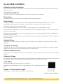
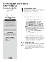
Cat 5 568‑B
Use Cat 5 568‑B wiring for connections. See Figure 1.
Compliance with IEEE 802.3 (at or af) specifications was not verified as part of UL
294.
Output 1 & 2 Connection Length
Connections to output 1 and 2 must be less than 98.5 feet.
Brown
Brown/White
Green
Blue/White
Blue
Green/White
Orange
Orange/White
1 2 3 4 5 6 7 8
Figure 1: Cat 5 568‑B Wiring

X1 & X1-8 DOOR CONTROLLER COMPLIANCE GUIDE | DIGITAL MONITORING PRODUCTS 2
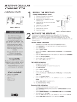
X1 DOOR CONTROLLER
Use 22‑18 gauge wire for all field wiring connections.
Voltage range for +12 output is 9.53 ‑ 13.53 VDC.
X1 firmware version 211 evaluated by Intertek.
Warning: Refer to you local state regulations before connecting to building power. Wiring methods
shall be in accordance with NEC, NFPA72, ANSI, and with all Authority Having Jurisdiction.
Wire the Input Power
Connect the transformer wires or external power to terminals 1 and 2 on the Door
Controller. Use no more than 70 ft. of 16 gauge or 40 ft. of 18 gauge wire between
the transformer and the Door Controller.
Wire the Battery
Connect the red battery lead to the battery positive terminal. Connect the black
battery lead to the negative battery terminal. Observe polarity when connecting
the battery.
The X1 was evaluated for 4 hours of standby power (level IV) using the UPG UB1290
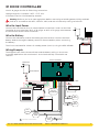
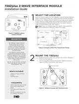
Wiring Example
The diagram here shows the transformer and the battery wiring. It also shows
a possible application with an electronic lock wired normally closed with wet
contacts.
+AC/DC- +BAT- R1 W1 G1 B1 LC BC R2 W2 G2 B2 LC BC DS RX CI G01 02 12V NC C NO
DRY WET
Red
12 V Battery
-
+
Orange/Brown
(Wiegand LED)
Card Reader
Red
White
Green Black
Optional
Second
Card Reader
Transformer
-
+
Power Indicator
Door
Contact
G
DS
Request
to Exit
G
RX
Custom
Input
G
CI
AUX
Output 1
12V
O1
12V
O2
AUX
Output 2
–+
Magnetic Lock
Jumper Set to Wet
NC
B2
XX = wire polarity or terminal location
X1 Door Controller
Battery Harness
Red
12 V Battery
-
+
+AC/DC- +BAT-
+-

X1 & X1-8 DOOR CONTROLLER COMPLIANCE GUIDE | DIGITAL MONITORING PRODUCTS 3
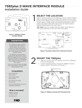
X1‑8 DOOR CONTROLLER
Voltage range for +12 output is 9.53 ‑
13.53 VDC.
Ground the Door Controller
Be sure to secure the green wire lead
to an earth ground. Connect to a cold
water pipe, ground rod, or building
ground when available. Connection
to an electrical ground or conduit can
also be used. Gas pipes or sprinkler
pipes should not be used.
Wire AC Power
Connect an unswitched 120 V AC 60 Hz power
source to the transformer. Knockouts are supplied
for power input.
Wire the Battery
The battery leads for the X1‑8 come pre‑wired.
Connect the red battery lead to the battery positive
terminal. Connect the black battery lead to the
negative battery terminal. Observe polarity when
connecting the battery. For additional power, use
the 318 Battery Harness with additional batteries
wired in parallel.
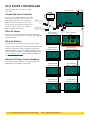
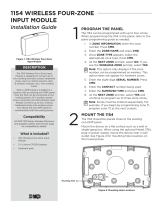
Wire the XD Door Control Modules
The door control modules come pre‑wired and
addressed in the order shown here.
100 VAC Wire-In
Transformer
Output
16 VDC @ 100 VA
DC
Battery Wires
to Battery
12 VDC @ 5 Amps
BAT
To X1 power
Input:
120 VAC 60 Hz 1.5
Amps Unswitched
Attach ground wire
to an enclosure mounting hole
To AC
To Earth Ground
+AC/DC-
0
1
2
3
4
5
6
7
8
9
0
1
2
3
4
5
6
7
8
9
0
1
2
3
4
5
6
7
8
9
0
1
2
3
4
5
6
7
8
9
0
1
2
3
4
5
6
7
8
9
0
1
2
3
4
5
6
7
8
9
0
1
2
3
4
5
6
7
8
9
Door Controller:
Door 1
Door Module 1:
Address 2, Door 2
Door Module 2:
Address 3, Door 3
Door Module 3:
Address 4, Door 4
Door Module 4:
Address 5, Door 5
Door Module 5:
Address 6, Door 6
Door Module 6:
Address 7, Door 7
Door Module 7:
Address 8, Door 8
+
-
+
-
+-
Red
Black
Black
White
Green
Violet
Gray
Model 505-12
0
1
2
3
4
5
6
7
8
9
0
1
2
3
4
5
6
7
8
9
0
1
2
3
4
5
6
7
8
9
0
1
2
3
4
5
6
7
8
9
0
1
2
3
4
5
6
7
8
9
0
1
2
3
4
5
6
7
8
9
0
1
2
3
4
5
6
7
8
9

X1 & X1-8 DOOR CONTROLLER COMPLIANCE GUIDE | DIGITAL MONITORING PRODUCTS 4
FCC INFORMATION
This device complies with Part 15 of the FCC Rules. Operation is subject to the following two conditions:
1. This device may not cause harmful interference, and
2. this device must accept any interference received, including interference that may cause undesired operation.
The antenna used for this transmitter must be installed to provide a separation distance of at least 20 cm (7.874 in.) from all persons. It
must not be located or operated in conjunction with any other antenna or transmitter.
Changes or modifications made by the user and not expressly approved by the party responsible for compliance could void the user’s
authority to operate the equipment.
Note: This equipment has been tested and found to comply with the limits for a Class B digital device, pursuant to
part 15 of the FCC Rules. These limits are designed to provide reasonable protection against harmful interference in a
residential installation. This equipment generates, uses and can radiate radio frequency energy and, if not installed and
used in accordance with the instructions, may cause harmful interference to radio communications. However, there is no
guarantee that interference will not occur in a particular installation. If this equipment does cause harmful interference to
radio or television reception, which can be determined by turning the equipment off and on, the user is encouraged to try
to correct the interference by one or more of the following measures:
1. Reorient or relocate the receiving antenna.
2. Increase the separation between the equipment and receiver.
3. Connect the equipment into an outlet on a circuit different from that to which the receiver is connected.
4. Consult the dealer or an experienced radio/TV technician for help.
INDUSTRY CANADA INFORMATION
This device complies with Industry Canada Licence‑exempt RSS standards. Operation is subject to the following two conditions:
1. This device may not cause interference, and
2. this device must accept any interference, including interference that may cause undesired operation of the device.
This system has been evaluated for RF Exposure per RSS‑102 and is in compliance with the limits specified by Health Canada Safety
Code 6. The system must be installed at a minimum separation distance from the antenna to a general bystander of 7.87 inches (20 cm)
to maintain compliance with the General Population limits.
Le présent appareil est conforme aux CNR d’Industrie Canada applicables aux appareils radio exempts de licence. L’exploitation est
autorisée aux deux conditions suivantes:
1. l’appareil ne doit pas produire de brouillage, et
2. l’utilisateur de l’appareil doit accepter tout brouillage radioélectrique subi, même si le brouillage est susceptible d’en
compromettre le fonctionnement.
L’exposition aux radiofréquences de ce système a été évaluée selon la norme RSS-102 et est jugée conforme aux limites établies par le
Code de sécurité 6 de Santé Canada. Le système doit être installé à une distance minimale de 7.87 pouces (20 cm) séparant l’antenne
d’une personne présente en conformité avec les limites permises d’exposition du grand public.

Designed, engineered,
and manufactured in
Springfield, Missouri
INTRUSION • FIRE • ACCESS • NETWORKS
2500 North Partnership Boulevard
Springfield, Missouri 65803-8877
800.641.4282 | dmp.com
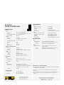
X1 & X1‑8
DOOR CONTROLLER
Specifications
Power
X1
Input 12 V ‑ 24 V AC/DC 2A
Battery 1.5 Ah (recommended), 9 Ah (max)
Power Output Max* 1.5 A; PoE 750 mA
O1, O2 Max 50 mA
X1-8
Input 12 V DC
Battery 2 x 9 Ah (recommended)
2 x 12 Ah (max)
Power Output Max**
505‑12 5 A
X1 1.5 A
XD 750 mA
O1, O2 Max 50 mA
Communication Options
X1
Ethernet 10/100
Wi‑Fi 2.4 GHz b/g/n
Cellular 263LTE‑A‑X1 (X1), 263LTE‑V‑X1 (X1)
X1-8
Ethernet 10/100
Wi‑Fi 2.4 GHz b/g/n
Cellular 263LTE‑A‑Z1/381‑2 (X1‑8),
263LTE‑V‑Z1/381‑2 (X1‑8)
Mechanical
X1
Enclosure 6.5” W x 8” H x 3” D
Dimensions 16.5 cm W x 20.3 cm H x 7.6 cm D
Weight 4 lbs
X1-8
Enclosure 14.5” W x 32” H x 4” D
Dimensions (lid adds 0.5" on each side)
36.8 cm W x 81.3 cm H x 10.2 cm D
(lid adds 1.3 cm on each side
Weight 34 lbs
Environmental
Temperature 0 ° C to 49 ° C
32 ° F to 120 ° F
Humidity 5% to 85% RHNC
Compatibility
X1
263LTE‑A‑X1 (X1) Cell Module
263LTE‑V‑X1 (X1) Cell Module
X1‑POE PoE Module
X1PCB PCB Replacement
X1‑OUT‑EXP X1 Output Expansion Module
X1-8
263LTE‑A‑X1/381‑2 (X1‑8) Cell Module for AT&T
263LTE‑V‑X1/381‑2 (X1‑8) Cell Module for Verizon
X1‑8PCB X1‑8 PCB Replacement
XDPCB XD PCB Replacement
X1‑OUT‑EXP X1 Output Expansion Module
Certifications
X1
ANSI/UL 294 Access Control System Units
Level I Destructive Attack and Line Security
Level IV Endurance and Standby Power
X1-8
ANSI/UL 294 Power Supplies for Access Control
System Units
Level I Destructive Attack and Line Security
Level IV Endurance and Standby Power
Manufacturer’s Limited Warranty
3 Year warranty against defects in materials and workmanship.
Visit DMP.com for full details.
* Max Power output is a board’s total avaible power for all attached
equipment
* *The 505‑12 is factory‑wired to supply power to all included modules.
If door hardware exceeds 5 A an additional power supply will be
required.
-
 1
1
-
 2
2
-
 3
3
-
 4
4
-
 5
5
-
 6
6


Digital Monitoring Products X1 SERIES SINGLE-DOOR AND MULTI-DOOR ACCESS CONTROLLER Compliance Guide
- Catégorie
- Contrôleurs de porte de sécurité
- Taper
- Compliance Guide
dans d''autres langues
Documents connexes
Autres documents
-
Paxton ins-20606 Mode d'emploi
-
-
 DMP Electronics 1158 Guide d'installation
-
Axis A1001 Manuel utilisateur
-
Alpha XM3.1-HP Broadband UPS Technical Manual
-
 DMP 738Zplus Manuel utilisateur
-
DMP 1118 Wireless Remote Indicator Light Guide d'installation
-
 DMP Electronics 1154 Guide d'installation


