
Spécifications Constructeur
FR
Notice d’installation
: HOTTES
Manufacturers Instructions
EN
I
nstall
ation manual
:
HOOD
Angaben des Herstellers
DE
Installationsanleitung
:
DUNSTABZUGSHAUBEN
Especificationes del Fabricante
ES
Manual de instalación
:
CAMPANAS
3
H
-
390
9
9
8
N
I
Ed: 04/2017


3H-390998NI – 04/17
HOBART GmbH
Robert Bosch Str. 17,
77656 Offenburg - Germany
A: CARACTÉRISTIQUES TECHNIQUES / TECHNICAL CHARACTERISTICS /
TECHNISCHE DATEN / CARACTERÍSTICAS TÉCNICAS
Le niveau de pression acoustique pondéré A est inférieur à 70 dB(A). / The balanced acoustic pressure level A is less than 70 dB(A). / Der A-
bewertete Schalldruckpegel liegt unter 70 dB(A). / El nivel de presión acústica ponderada A es inferior a 70 dB (A).
PLAQUE SIGNALETIQUE / DATA PLATE / TYPENSCHILD / PLACA INFORMATIVA
Pour toute correspondance relative à votre matériel, rappeler toujours / In any correspondence about your equipment, please indicate / Bei
jeder Kontaktaufnahme mit dem Kundendienst in Zusammenhang mit Ihrem Gerät, bitten wir Sie folgende Angaben bereit zu halten / Para cualquier
correspondencia relativa a su material recuerde siempre:
- Le numéro de modèle (Model.) / The model number / Modellnummer / El número de modelo
- Le numéro de série (Fabr. Nr) / The serial number / Seriennummer / El número de serie
- La date (date) / The date / Datum / La fecha
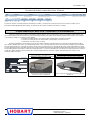
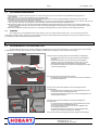
La plaque signalétique se trouve apposée à l’arrière de la hotte Combi Mini et derrière le filtre à choc droit de la hotte 6&10 niveaux GN 1/1
(voir chapitre « Entretien de la hotte » pour le démontage du filtre à choc) / The data plate is located on the back of the Combi Mini hood and behind
the main right hand filter on 6 & 10 level oven hoods (see the section on “Maintenance” for removing the filter) / Das Typenschild befindet sich hinten
an der Kondensationshaube Combi Mini und hinter dem rechten Prallflächenabscheider der Dunstabzugshaube 6&10 Einschübe GN 1/1 (zum Ausbau
der Dunstabzugshaube siehe Kapitel « Pflege der Dunstabzugshaube ») / La placa de identificación se encuentra en la parte posterior de la campana
Combi Mini y detrás del filtro de choque derecho de la campana 6&10 niveles GN 1/1 (véase capítulo « Mantenimiento de la campana » para
desmontar el filtro de choque).
77656 Offenburg - Germany
Robert Bosch Str. 17,
HOBART GmbH
Four Combi Mini / Combi Mini oven /
Kombidämpfer Combi Mini / Horno Combi Mini
Fours 6 et 10 niveaux GN1/1 et superposés / 6 & 10
level GN1/1 and stacked ovens / Kombidämpfer 6 und
10 Einschübe GN 1/1 und übereinander gestellte Geräte
/ Hornos de 6 y 10 niveles GN1/1 y superpuestos
Emplacement de la plaque signalétique / Location of
the data plate / Position des Typenschilds /
Ubicación de la placa de identificación
Emplacement de la plaque signalétique / Location of the data
plate / Position des Typenschilds / Ubicación de la placa de
identificación
CODE Designation Designation Bezeichnung Denominación Energie Energy Energie Energia
HAC6&11HE Accessoire 6&10 niveaux GN1/1 Hotte (Elec) Accessory 6&10 Levels GN1/1 Hood (Elec) Zubehör 6&10 Ebenen GN1/1 Kondensationshaube (Elek) Accesorio 6&10 niveles GN1/1 Campana (Elec) Electrique Electric Elektrisch Eléctrica
HACM6H Accessoire Mini 6 Hotte Accessory Mini 6 Hood Zubehör Mini 6 Kondensationshaube Accesorio Mini 6 Campana Electrique Electric Elektrisch Eléctrica
CODE U Lib KwE Imax (A)
Poids / Weight /
Gewicht / Peso (Kg)
Avancée / Depth /
Tiefe / Profundidad
Largeur / Width /
Breite / Anchura
Hauteur / High /
Höhe / Altura
HAC6&11HE 230 a.c. 0,20 1,30 66,00 1080 920 405
HACM6H 230 a.c. 0,10 0,40 32,00 915 528 177

3H-390998NI – 04/17
HOBART GmbH
Robert Bosch Str. 17,
77656 Offenburg - Germany

Spécifications Constructeur
FR
Notice d’installation
: HOTTES

Page 1 3H-390998NI – 04/17
HOBART GmbH
Robert Bosch Str. 17,
77656 Offenburg - Germany
SOMMAIRE
HOTTES
ELECTRIQUES
A) CARACTERISTIQUES TECHNIQUES
PLAQUE SIGNALETIQUE
B) NOTICE TECHNIQUE DESTINEE A L'INSTALLATEUR
1 INSTALLATION ............................................................................................................................................................................. 2
2 INSTALLATION: MISE EN PLACE ............................................................................................................................................... 2
3 INSTALLATION: RACCORDEMENTS .......................................................................................................................................... 3
-
GARANTIE
-
Pour nous permettre de vous assurer la garantie de ces équipements, nous vous engageons à respecter les SPECIFICATIONS CONSTRUCTEUR,
consignées dans le présent manuel.
Si toutefois, vous n'étiez pas en mesure d'assurer l'entretien et la maintenance demandés, notre réseau d'installation et de service de proximité se
tient à votre entière disposition pour vous étudier un contrat personnalisé.
-
AVERTISSEMENT
-
•
Le produit qui vous est livré est en conformité avec les normes en vigueur. En cas de transformation, l'intervenant endosse la responsabilité
de constructeur. Le constructeur ne saurait être responsable en cas d'utilisation à des fins autres que celles pour lesquelles la machine est
conçue.
•
Il est impératif de laisser l'appareil sur son socle lors des manipulations jusqu'à l'implantation définitive.
•
Appareils à usage seulement professionnel, doivent être utilisés par du personnel qualifié.
•
Lire attentivement ce document avant l'installation.
•
Conserver vos documents.
•
Notice originale.

Page 2 3H-390998NI – 04/17
HOBART GmbH
Robert Bosch Str. 17,
77656 Offenburg - Germany
1 INSTALLATION
1.1 EXIGENCES GENERALES
L'installation, la modification ou la réparation de l'appareil doit être effectuée selon les règles de l'art par un installateur et réparateur qualifié.
Le matériel doit être installé dans une pièce normalement ventilée.
Toujours installer le four équipé de sa hotte dans un local naturellement aéré, ou disposant d’un renouvellement d’air conforme à la
réglementation en vigueur.
Si ces appareils sont installés en position adossée contre une cloison ou un mur, ceux-ci devront être réalisés en matériaux non combustibles ou,
si ce n'est pas le cas, devront être recouverts d'un matériau approprié, bon isolant, non combustible.
Le constructeur déclare que l'emballage est conforme à la directive 94/62/CE (directive emballages et déchets d’emballages du 20.12.94) et
invite l'installateur (et l'utilisateur) à respecter les règles relatives à l'enlèvement des emballages (recyclage ou revalorisation).
Il est impératif de respecter une distance minimum de 500mm au-dessus de la hotte pour un bon fonctionnement de celle-ci.
1.2 MANUTENTION
La manutention ne doit être effectuée qu'avec des engins de levage adaptés. Si l'appareil doit être transporté, il doit l'être sur sa palette
d'origine et ne doit en aucun cas être superposé à d'autres appareils. Lors d'un déplacement et en l'absence de sa palette, l'appareil doit être porté et
non tiré.
2 INSTALLATION: MISE EN PLACE
2.1 SUR LE FOUR 6 & 10 NIVEAUX GN 1/1 ET FOURS SUPERPOSES 6+6 & 6+10 NIVEAUX
La Hotte à condensation est à positionner uniquement sur le dessus des fours électriques 6 et 10 niveaux GN 1/1 et des fours superposés 6+6
et 6+10 niveaux de marque HOBART. En suivant les instructions ci-dessous :
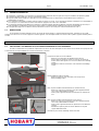
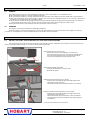
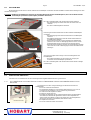
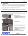
Positionner la hotte sur le Four HOBART :
- Retirer les 3 vis de fixation de l’habillage arrière du four
- Poser la hotte sur le dessus du four. Les trous de la cornière de
fixation doivent être alignés avec les trous de fixation de l’habillage
arrière.
- Immobiliser la hotte en revissant les 3 vis de fixation de l’habillage
arrière.
Retirer l’habillage arrière de la hotte :
- Dévisser et retirer les 6 vis de fixation (3 de chaque côté)
- Retirer l’habillage arrière
Mise en place du bulbe du thermostat dans la cheminée du four:
- Dévisser le contre écrou de fixation de la pâte support thermostat
sur la cloison intermédiaire de la hotte
- Saisir la patte support thermostat et l’insérer dans la cheminée du
four
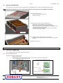
Mise en place du bulbe du thermostat dans l’Oura du four:
- Dévisser le contre écrou de fixation de la pâte support thermostat
sur la cloison intermédiaire de la hotte
- Saisir la patte support thermostat et la positionner sur le déflecteur
du Oura.
- Immobiliser la patte en pliant la cornière inférieure de la patte
support bulbe thermostat
Remettre en place et fixer l’habillage arrière de la hotte
Vis
Cornière
Déflecteur
du Oura

Page 3 3H-390998NI – 04/17
HOBART GmbH
Robert Bosch Str. 17,
77656 Offenburg - Germany
2.2 SUR LE COMBI MINI
La Hotte à condensation est à positionner uniquement sur le dessus des fours électriques Combi Mini. En suivant les instructions ci-dessous:
Remarque : Faire le raccordement électrique de la hotte sur le four avant de positionner la hotte sur le dessus du four (Voir le
chapitre « Installation : Raccordement »).
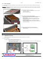
Retirer l’habillage supérieur de la hotte :
- Dévisser et retirer les 7 vis de fixation sur le dessus de la hotte
- Retirer l’habillage supérieur
Positionner la hotte sur le Four Combi Mini HOBART :
- Retirer les 2 vis de fixation de l’habillage arrière du four.
- Retirer la vis centrale de fixation des deux habillages de côté du
four.
- Poser la hotte sur le dessus du four. Les trous de la cornière de
fixation doivent être alignés avec les trous de fixation de l’habillage
arrière.
- Immobiliser la hotte en revissant les 2 vis de fixation de l’habillage
arrière et les 2 vis de fixation des habillages de côté.
Raccordement du serpentin de cuivre avec la cheminée du four:
- Positionner le coude cuivre sur le joint en sortie du tube de
cheminée du four
Remettre en place et fixer l’habillage supérieur de la hotte
3 INSTALLATION: RACCORDEMENTS
3.1 RACCORDEMENT ELECTRIQUE
• N'utiliser que le câble d'alimentation de type H07 RN-F fourni avec la hotte.
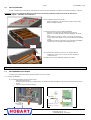
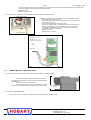
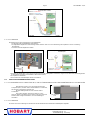
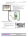
3.1.1 SUR LE COMBI MINI
Le raccordement électrique se fait à l'arrière du four.
- Démonter l’arrière du four.
- Installer le presse-étoupe et la rondelle fournis. Une prédécoupe permet de libérer un trou pour le positionnement du presse-
étoupe.
- Passer le câble par le presse-étoupe.
Position du presse-étoupe Schéma de raccordement de la hotte sur le four
Vis
Vis
joint
Câble
d’alimentation
de la hotte
Carte relais
Câble Hotte
Borne 34
→
Fil bleu
Borne 4
→
Fil rouge

Page 4 3H-390998NI – 04/17
HOBART GmbH
Robert Bosch Str. 17,
77656 Offenburg - Germany
- Brancher les fils du câble d’alimentation sur les bornes correspondantes de la carte Relais sans oublier de raccorder le fil de
terre sur la borne de la platine électrique (Voir schémas ci-dessus).
- Serrer le presse-étoupe.
- Remonter l’arrière du four.
3.1.2 SUR LE FOUR 6 ET 10 NIVEAUX GN 1/1 ET FOURS SUPERPOSES 6+6 ET 6+10 NIVEAUX
Position du presse-étoupe
Le raccordement électrique se fait à l'arrière droit du four quel que soit le
modèle.
- Démonter le côté droit du four.
- Installer le presse-étoupe et la rondelle fournis. Une prédécoupe
permet de libérer un trou pour le positionnement du presse-étoupe.
- Passer le câble par le presse-étoupe.
- Brancher les fils du câble d’alimentation sur les bornes
correspondantes de la carte Relais (si fours superposés, raccorder sur
la carte relais du four inférieur) sans oublier de raccorder le fil de terre
sur la borne de la platine électrique (Voir schémas ci-dessous).
- Serrer le presse-étoupe.
- Remonter le côté droit du four.
Schéma de raccordement de la hotte sur fours
*Si fours superposés : raccorder le fils noir avec le fil rouge
sur la borne 1
3.2 RACCORDEMENT EVACUATION CONDENSATS
3.2.1 SUR LE FOUR 6 & 10 NIVEAUX GN 1/1 ET FOURS SUPERPOSES 6+6 & 6+10 NIVEAUX
Les eaux évacuées peuvent être des condensats à hautes
températures (98°C). Utiliser de ce fait, des matériaux adaptés à
ces températures.
Raccorder la hotte à une vidange externe.
En cas de raccordement étanche sur la vidange externe, il
est impératif d’avoir un siphon entre l’appareil et le réseau de
vidange pour prévenir les remontées d’odeurs.
3.2.2 SUR LE COMBI MINI
Aucun raccordement n’est nécessaire. Les condensats sont évacués directement par la vidange du four.
∅ 10 minimum
intérieur
Câble d’alimentation de
la hotte
Carte relais
Câble Hotte
Borne 7
→
Fil rouge*
Borne 3
→
Fil bleu
Borne 1
→
Fil noir*

Page 5 3H-390998NI – 04/17
HOBART GmbH
Robert Bosch Str. 17,
77656 Offenburg - Germany

Manufacturers Instructions
EN
I
nstall
ation manual
:
HOOD

Page 1 3H-390998NI – 04/17
HOBART GmbH
Robert Bosch Str. 17,
77656 Offenburg - Germany
CONTENT
HOOD
ELECTRIC
A) TECHNICAL CHARACTERISTICS
DATA PLATE
B) TECHNICAL INSTRUCTIONS FOR THE INSTALLER
4 INSTALLATION ............................................................................................................................................................................. 2
5 INSTALLATION: LOCATION ........................................................................................................................................................ 2
6 INSTALLATION: CONNECTIONS ................................................................................................................................................. 3
-
WARRANTY
-
To ensure the guarantee on this equipment, you should comply with the MANUFACTURER’S INSTRUCTIONS in this manual.
However if you cannot undertake the required maintenance operations, our installation and service network is available to provide you with a
personalized contract.
-
WARNING
-
•
The product delivered to you complies with current standards. If any modifications are made the manufacturer cannot accept any
responsibility whatsoever. The manufacturer cannot be held responsible in the event of inappropriate use of the equipment.
•
This equipment is intended for use by suitably trained professionals.
•
When handling it, it is imperative to leave the appliance on its base till final installation.
•
Read all the documentation before installation.
•
Keep your documents for future reference.
•
Translation of the original manual

Page 2 3H-390998NI – 04/17
HOBART GmbH
Robert Bosch Str. 17,
77656 Offenburg - Germany
4 INSTALLATION
4.1 GENERAL
A qualified engineer must carry out the installation, modification or repair of the appliance in a workmanlike manner.
The unit should be installed in a normally ventilated environment.
The unit should be installed in a normally ventilated environment or having an air handling system that complies with current regulations.
These units should only be placed against a wall or a partition. This must be of non-combustible materials or, if not, must be covered with an
appropriate, good insulating and non-combustible material.
The manufacturer certifies that the packaging meets the provision 94/62/CE (relating to packaging and packaging waste of 20.12.94) and
requests that the final installer (or user) observes the rules relating to the removal of the packaging (recycling or reuse).
It is imperative that there is at least 500mm clear above the hood for it to work correctly.
4.2 HANDLING
The appliance should only be handled with suitable lifting equipment.
Should the appliance need to be transported, this must be on its original pallet and it must not be stacked on other appliances under any
circumstances. If the appliance is to be moved without its pallet, it should be carried and not pulled.
5 INSTALLATION: LOCATION
5.1 ON THE 6 & 10 LEVEL GN 1/1 OVEN AND 6+6 & 6+10 LEVEL STACKED OVENS
This condensing hood only fits onto the top of Hobart 6 and 10 level GN1/1 electric combination ovens and 6+6 & 6+10 level stacked ovens
from the Combi and Combi Plus ranges. In accordance with the following instructions:
Positioning the hood on a Hobart oven:
- Remove the 3 fixing screws holding the oven back panel
- Place the hood on top of the oven. The holes in the bracket under
the hood should align with the holes for fixing the back panel.
- Fix the hood by refitting the 3 panel retaining screws.
Removing the hoods rear panel:
- Unscrew the 6 fixings (3 on each side)
- Remove the panel
Fitting the thermostat bulb in the oven chimney:
- Undo the back nut holding the thermostat support plate to the
intermediate casing in the hood
- Take the thermostat support and insert it into the oven chimney
Fitting the other thermostat bulb into the oven vent outlet:
- Undo the back nut holding the thermostat support plate to the
intermediate casing in the hood
- Take the thermostat support and locate it on the Vent deflector.
- Fix the plate permanently by bending the lower edge against the
vent deflector
Put the rear panel back in place and fasten it.
Screws
Bracket
Vent
deflector

Page 3 3H-390998NI – 04/17
HOBART GmbH
Robert Bosch Str. 17,
77656 Offenburg - Germany
5.2 ON THE COMBI MINI OVEN
This condensing hood only fits onto the top of Hobart electric COMBI MINI ovens. In accordance with the following instructions:
Note: Electrically connected the hood to the oven before placing the hood on top of the oven (See "Installation: Connecting").
Remove the hoods top cover:
- Undo and remove the 7 fixing screws
- Lift the top cover off
Located the hood on top of a Hobart Combi Mini oven:
- Remove the 2 screws holding the ovens back panel.
- Remove the central fixing screws holding the side panels.
- Place the hood on the oven. The holes in the rear fixing strip should
align with the holes in the rear panel.
- Fix the hood in place by refitting the two sets of 2 screws holding
the rear and side panels in place.
Connecting the copper serpentine with the oven chimney:
- Position the copper elbow on the seal where the chimney pipe exits
the oven
Refit the hoods top panel
6 INSTALLATION: CONNECTIONS
6.1 ELECTRICAL CONNECTION
• Only use the H07 RN-F supply cable provided with the hood.
6.1.1 ON THE COMBI MINI OVEN
Electrical connection is to the rear of oven.
- Remove the rear panel.
- Fit the cable gland and washer provided. There is a pre-cut knock out hole for the cable gland.
- Pass the hood supply cable through the gland.
Cable gland position The hood connection diagram on oven
Screws
Seal
Screws
Hood cable
Hood supply
cable
Relay card
Terminal 34
→
Blue wire
Terminal
4
→
Red wire

Page 4 3H-390998NI – 04/17
HOBART GmbH
Robert Bosch Str. 17,
77656 Offenburg - Germany
- Connect the supply cables to the corresponding connection points on the relay card without forgetting to connect the earth
wire to the terminal on the electronic board (See diagrams).
- Tighten the gland.
- Refit the oven rear panel.
6.1.2 ON THE 6 & 10 LEVEL GN 1/1 OVENS AND 6+6 & 6+10 LEVEL STACKED OVENS
Cable gland position
Electrical connection is to the rear right hand side on all models of oven.
- Remove the right hand side panel.
- Fit the cable gland and washer provided. There is a pre-cut knock out
hole for the cable gland.
- Pass the hood supply cable through the gland.
- Connect the supply cables to the corresponding connection points on
the relay card (if stacked ovens, connect on the relay card of lower
oven) without forgetting to connect the earth wire to the terminal on
the electronic board (See diagrams).
- Tighten the gland.
- Refit the oven side panel.
The hood connection diagram on Ovens
*If stacked ovens: connect the black wire with the red wire on
the terminal 1
6.2 CONNECTING THE CONDENSATE DRAIN
6.2.1 ON THE 6 & 10 LEVEL GN 1/1 OVENS AND 6+6 & 6+10 LEVEL STACKED OVENS
The water discharged could be condensed steam and at
very high temperature (98°C). Only use materials suitable for these
temperatures.
Connect the hood to an external drain.
If connecting directly to waste, It is vital that there is a trap
between the unit and the drainage system to prevent back odours.
6.2.2 ON THE COMBI MINI OVEN
No connection needs to be made. Condensates are discharged directly to the ovens drain.
Hood supply cable
10mm ∅
minimum
internal
Relay card
Hood cable
Terminal 7
→
Red wire*
Terminal 3
→
Blue wire
Terminal 1
→
Black wire*

Page 5 3H-390998NI – 04/17
HOBART GmbH
Robert Bosch Str. 17,
77656 Offenburg - Germany

Angaben des Herstellers
DE
Installationsanleitung
:
DUNSTABZUGSHAUBEN

Page 1 3H-390998NI – 04/17
HOBART GmbH
Robert Bosch Str. 17,
77656 Offenburg - Germany
INHALT
ELEKTRISCHE
DUNSTABZUGSHAUBEN
A) TECHNISCHE DATEN
TYPENSCHILD
B) TECHNISCHE ANLEITUNG FÜR DEN MONTEUR
7 INSTALLATION ............................................................................................................................................................................. 2
8 INSTALLATION: AUFSTELLUNG ................................................................................................................................................ 2
9 INSTALLATION: ANSCHLÜSSE .................................................................................................................................................. 3
-
GARANTIE
-
Um Ihnen die Garantieleistung unserer Geräte bieten zu können, bitten wir Sie, die im vorliegenden Handbuch gemachten ANGABEN DES
HERSTELLERS zu beachten.
Sollte es dennoch nicht möglich sein, die benötigte Pflege und Instandhaltung zu gewährleisten, steht Ihnen unser Netzwerk bestehend aus
Installateuren und Service-Mitarbeitern in Ihrer Nähe gerne zur Verfügung, um für Sie einen individuellen Vertrag auszuarbeiten.
-
WARNHINWEIS
-
•
Das gelieferte Gerät entspricht den geltenden Normen. Bei nicht vom Hersteller autorisierten Änderungen übernimmt derjenige, der die
Änderung vorgenommen hat, die Haftung des Herstellers. Der Hersteller übernimmt keine Haftung, wenn das Gerät nicht bestimmungsgemäß
verwendet wird.
•
Bei allen Handhabungen bis zur endgültigen Aufstellung muss das Gerät unbedingt auf seinem Sockel verbleiben.
•
Die Geräte sind ausschließlich für den gewerbsmäßigen Gebrauch bestimmt und dürfen nur von qualifiziertem Personal bedient werden.
•
Vor der Installation ist dieses Dokument aufmerksam zu lesen.
•
Bewahren Sie diese Dokumente sicher auf.
•
Übersetzte Version der originalen Anleitung.

Page 2 3H-390998NI – 04/17
HOBART GmbH
Robert Bosch Str. 17,
77656 Offenburg - Germany
7 INSTALLATION
7.1 ALLGEMEINE ANFORDERUNGEN
Die Installation, Veränderung oder Reparatur des Geräts ist fachgerecht von einem Monteur oder qualifiziertem Wartungspersonal
durchzuführen.
Das Gerät muss in einem normal belüfteten Raum installiert werden.
Installieren Sie den mit seiner Haube ausgestatteten Kombidämpfer immer in einem natürlich belüfteten Raum oder in einem Raum mit
Raumlufterneuerung gemäß den geltenden Vorschriften.
Falls die Geräte an einer Wand oder Mauer installiert werden, muss diese aus nicht brennbarem Material bestehen oder, falls dies nicht der Fall
sein sollte, muss diese mit einem geeigneten, gut isolierenden und nicht brennbaren Material verkleidet werden.
Der Hersteller erklärt, dass die Verpackung der Richtlinie 94/62/EG entspricht (Richtlinie über Verpackungen und Verpackungsabfälle vom
20.12.94) und bittet den Monteur (und den Anwender), die Regelungen bezüglich der Entsorgung von Verpackungen einzuhalten (Recycling
oder Verwertung).
Für einen störungsfreien Betrieb der Haube muss unbedingt ein Mindestabstand von 500mm über der Haube eingehalten werden.
7.2 HANDLING
Das Handling darf nur mit geeigneten Hebezeugen erfolgen. Falls das Gerät transportiert werden muss, muss der Transport auf seiner
ursprünglichen Palette erfolgen, wobei das Gerät keinesfalls auf andere Geräte gestellt werden darf. Erfolgt ein Transport ohne Palette, muss das
Gerät getragen werden und darf keinesfalls gezogen werden.
8 INSTALLATION: AUFSTELLUNG
8.1 AUF KOMBIDÄMPFER 6 & 10 EINSCHÜBE GN 1/1
Die Dunstabzugshauben darf nur auf dem elektrischen Kombidämpfer mit 6 und 10 Einschüben GN 1/1 und auf den übereinander gestellten
Kombidämpfern 6+6 und 6+10 Einschübe der Marke HOBART installiert werden. Befolgen Sie unten stehende Anweisungen:
Platzierung der Dunstabzugshaube auf dem HOBART-Kombidämpfer:
- Die 3 Befestigungsschrauben der Rückwand des Kombidämpfers
entfernen.
- Die Dunstabzugshaube auf dem Oberteil des Kombidämpfers
platzieren. Die Löcher des Befestigungswinkels müssen auf die
Befestigungsbohrungen der Rückwand ausgerichtet werden.
- Die Haube durch Wiederanschrauben der 3 Befestigungsschrauben
der Rückwand befestigen.
Die Rückwand der Dunstabzugshaube entfernen:
- Die 6 Befestigungsschrauben (3 auf jeder Seite) lösen und entfernen.
- Die Rückwand abnehmen.
Einsetzen des Thermostat-Kapillarrohrs im Dunstabzugskamin des
Kombidämpfers:
- Die Gegenmutter der Befestigung der Thermostathalterung auf der
Zwischenwand der Dunstabzugshaube lösen.
- Die Thermostathalterung nehmen und in den Dunstabzugskamin des
Kombidämpfers einführen.
Einsetzen des Thermostat-Kapillarrohrs in die Wrasenklappe des
Kombidämpfers:
- Die Gegenmutter der Befestigung der Thermostathalterung auf der
Zwischenwand der Dunstabzugshaube lösen.
- Die Thermostathalterung nehmen und auf dem Luftleitblech der
Wrasenklappe positionieren.
- Die Halterung befestigen, indem Sie das untere Winkelprofil der
Halterung des Thermostat-Kapillarrohrs umbiegen.
Die Rückwand der Dunstabzugshaube wieder anbringen und befestigen.
Schrauben
Winkelprofil
Luftleitblech der
Wrasenklappe

Page 3 3H-390998NI – 04/17
HOBART GmbH
Robert Bosch Str. 17,
77656 Offenburg - Germany
8.2 AUF COMBI MINI
Die Kondensationshaube darf nur auf dem elektrischen Kombidämpfer Combi Mini der Marke HOBART installiert werden. Befolgen Sie unten
stehende Anweisungen:
Bemerkung: Stellen Sie den elektrischen Anschluss der Kondensationshaube auf dem Kombidämpfer her, bevor Sie die Haube auf dem
Kombidämpfer positionieren (siehe Kapitel „Installation: Anschluss“).
Das obere Verkleidungsblech der Kondensationshaube entfernen:
- Die 7 Befestigungsschrauben am Deckel der Haube lösen und
entfernen.
- Das obere Verkleidungsblech abnehmen.
Platzierung der Kondensationshaube auf dem HOBART-Kombidämpfer
Combi Mini:
- Die 2 Befestigungsschrauben der Rückwand des Kombidämpfers
entfernen.
- Die mittlere Befestigungsschraube der beiden Seitenwände des
Kombidämpfers entfernen.
- Die Kondensationshaube auf dem Oberteil des Kombidämpfers
platzieren. Die Löcher des Befestigungswinkels müssen auf die
Befestigungsbohrungen der Rückwand ausgerichtet werden.
- Die Haube durch Wiederanschrauben der 2 Befestigungsschrauben
der Rückwand und der 2 Befestigungsschrauben der Seitenwände
befestigen.
Anschluss der Kupfer-Rohrschlange an den Dunstabzugskamin des
Kombidämpfers:
- Das Kupfer-Winkelstück auf der Dichtung am Ausgang des
Kaminrohrs des Kombidämpfers positionieren.
Das obere Verkleidungsblech der Kondensationshaube wieder anbringen
und befestigen.
9 INSTALLATION: ANSCHLÜSSE
9.1 ELEKTRISCHER ANSCHLUSS
• Benutzen Sie ausschließlich das mit der Dunstabzugshaube mitgelieferte Netzkabel des Typs H07 RN-F
9.1.1 AUF KOMBIDÄMPFER 6 & 10 EINSCHÜBE GN 1/1 UND AUF ÜBEREINANDER GESTELLTEN KOMBIDÄMPFERN 6+6 & 6+10
EINSCHÜBE
Position der Stopfbuchse Der elektrische Anschluss erfolgt unabhängig vom Modell rechts hinten am
Kombidämpfer.
- Die rechte Geräteseite abmontieren.
- Die mitgelieferte Stopfbuchse und Unterlegscheibe einbauen. Das Loch zur
Positionierung der Stopfbuchse an der Vorstanzung durchdrücken.
- Das Kabel durch die Stopfbuchse führen.
- Remonter le côté droit du four.
- Die Drähte des Netzkabels an den entsprechenden Klemmen der Relaisplatine
anschließen (bei übereinander gestellten Geräten an der Relaisplatine des
unteren Geräts anschließen); vergessen Sie dabei nicht, das Erdungskabel an
der Klemme der Platine anzuschließen (siehe Skizzen unten).
- Die Stopfbuchse festziehen.
- Die rechte Geräteseite wieder anmontieren.
Schrauben
Dichtung
Schrauben
Netzkabel der Haube
La page est en cours de chargement...
La page est en cours de chargement...
La page est en cours de chargement...
La page est en cours de chargement...
La page est en cours de chargement...
La page est en cours de chargement...
La page est en cours de chargement...
-
 1
1
-
 2
2
-
 3
3
-
 4
4
-
 5
5
-
 6
6
-
 7
7
-
 8
8
-
 9
9
-
 10
10
-
 11
11
-
 12
12
-
 13
13
-
 14
14
-
 15
15
-
 16
16
-
 17
17
-
 18
18
-
 19
19
-
 20
20
-
 21
21
-
 22
22
-
 23
23
-
 24
24
-
 25
25
-
 26
26
-
 27
27


Hobart HACM6H Guide d'installation
- Taper
- Guide d'installation
dans d''autres langues
- English: Hobart HACM6H Installation guide
- español: Hobart HACM6H Guía de instalación
- Deutsch: Hobart HACM6H Installationsanleitung
Documents connexes
Autres documents
-
 OURA Gucci Mode d'emploi
-
MBM MC202E Use And Routine Maintenance Manual
-
Bartscher 116806 Le manuel du propriétaire
-
 VULCAN & WOLF 3V-490058NI TCM Series Combi Oven Guide d'installation
-
AEG EXPRESSKOCHEWA1013 Manuel utilisateur
-
AEG FOEN1014PIANISSIMO Manuel utilisateur
-
-
Meiko K-Tronic Manuel utilisateur

