Risco WatchOUT XTreme 315DT Installation Instructions Manual
- Taper
- Installation Instructions Manual

EN
IT
ES
FR
PR
NL
Dual Technology Outdoor Detector
Rivelatore da Esterno a Doppia Tecnologia
Detector de Exterior de Doble Tecnología
Détecteur extérieur à double technologie
Detector Externo de Dupla Tecnologia
Dual Technology-Buitendetector
WatchOUT 315DT
Installation Instructions - Relay & BUS Modes
Istruzioni per l’installazione in modalità Relé e BUS
Instrucciones de Instalación - Modos Relé y BUS
Guide d'installation - Modes Relais et BUS
Instruções de Instalação - Modos Relé & BUS
Relais- & BUS-modusinstallatie-instructies

2 WatchOUT 315DT Installation Manual

WatchOUT 315DT Installation Manual 3
EN
Table of Contents
Relay Mode Installation .......................................................................................................... 4
Introduction ............................................................................................................................ 4
Mounting ................................................................................................................................. 4
Mounting Considerations...................................................................................................... 4
Wall Mount Installation ......................................................................................................... 5
Flat Mounting: ...................................................................................................................... 5
45° angle Mounting (Left side mounting) .............................................................................. 5
Changing Back Tamper position .......................................................................................... 6
Terminal Wiring ..................................................................................................................... 6
DIP Switch Settings ................................................................................................................. 7
Microwave Adjustment........................................................................................................... 7
Walk test .............................................................................................................................. 7
LEDs Display ........................................................................................................................... 7
Relay Mode / BUS Mode Jumper .......................................................................................... 8
Standard Swivel Installation .................................................................................................. 8
Wall Mounting ...................................................................................................................... 8
Swivel Conduit Mounting ...................................................................................................... 8
Replacing a Lens................................................................................................................... 10
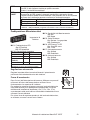
Lenses Types..................................................................................................................... 11
Technical Specification ......................................................................................................... 12
Ordering Information........................................................................................................... 12
UL Compliance Section ........................................................................................................ 12
BUS Mode Installation .......................................................................................................... 13
Introduction .......................................................................................................................... 13
Terminal Wiring ................................................................................................................... 13
DIP Switch Settings ............................................................................................................... 13
ProSYS Programming ........................................................................................................... 14
New System Parameters ...................................................................................................... 16

4 WatchOUT 315DT Installation Manual
Relay Mode Installation
Introduction
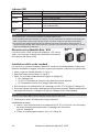
RISCO Group's Dual Technology Outdoor Detector, WatchOUT 315DT, is a unique detector with
signal processing based on two Passive Infrared (PIR) channels and two Microwave (MW)
channels. The detector can operate as a regular relay detector connected to any control panel, or
as a BUS accessory when connected to RISCO Group's ProSYS control panel via the RS485
BUS, thus having unique remote control and diagnostic capabilities.
The instructions describe herein, describe the WatchOUT 315DT in Relay & BUS mode.
Mounting
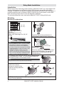
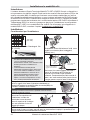
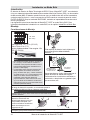
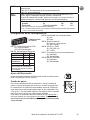
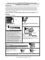
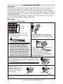
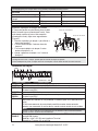
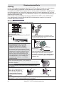
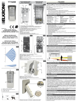
Mounting Considerations
1m - 2.7m
(3'3" - 8'9")
Optional Height: 1m - 2.7m
(3'3"-8'9")
Typical Height: 2.2m (7'2")
Default Lens: Wide angle 15m (50') 90°
(RL300)
Note:
1. For low installations, below 1.7m (5'6") in which
pet immunity is required, use the supplied
RL300F lens (low wall or fence installations).
2. The detector's pet immunity (height of an animal,
no weight limitation), is up to 70 cm (2'4"), when
installing the detector at 2.2m (7'2"). If the
installation is bellow the height mentioned
above, the Pet Immunity decreases accordingly;
every 10 cm (4") decrease in installation height
leads to 10 cm (4") decrease in pet imunity.
If possible, avoid pointing the detector to
moving objects (swaying trees, bushes etc.)
Out of
Detection Range
Keep distance of
minimum 5m (16')
from moving objects
5m (16')
Ensure any objects do not obstruct the field of
view for both technologies. Pay attention to
growing trees or bushes, plants with big
moving leaves etc
For installations with extensive vehicle traffic or targets beyond
the required detection range, it is recommended to adjust the
MW sensitivity and/or to tilt the detector down.
Note:
Tilting the detector down may reduce the pet immunity
For optimum detection, select a
location that is likely to
intercept an intruder moving
across the coverage pattern at
a 45° trajectory.
NOTE: Disable Proximity AM during heavy rain (if WatchOUT 315DT is not sheltered) to
prevent Proximity AM alerts.

WatchOUT 315DT Installation Manual 5
EN
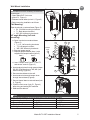
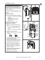
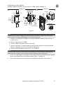
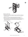
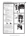
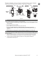
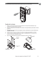
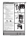
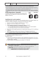
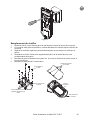
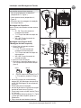
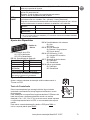
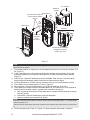
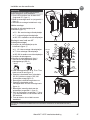
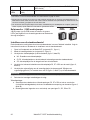
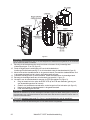
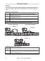
Wall Mount Installation
Note:
The installation knockouts numbering are marked on
the back plate.
1. Open WatchOUT front cover
(unlock C1, Figure 1).
2. Release internal base (unlock I1, Figure 2).
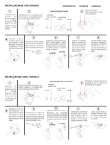
3. Select mounting installation as follows:
Flat Mounting:
Open knockouts on external base (Figure 3).
• B1 - B4: Wall mounting knockouts
• T1: Back tamper knockout
• W2 / W3: wires entry knockouts
45° angle Mounting (Left side
mounting)
a. Open knockouts on external base
(Figure 3)
• L1, L2: Left mounting knockouts
• T3: Left tamper knockout
• W5 / W6: Wire entry knockouts
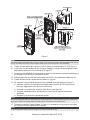
b. Remove tamper spring.
c. Replace tamper bracket (Item 1) with
supplied flat tamper bracket (Item 2).
Item 1
Item 2
d. Insert Tamper lever B onto T5 and T3
and secure screw A (Figure 3).
4. Insert external wires through external base
W2, W3 (Flat Mounting) or W5, W6 (Left
side mounting) (Figure 3).
5. Secure external base to the wall.
6. Insert external wires and tamper wires
through internal base (Figure4).
7. Secure internal base to external base (lock
I1, Figure2).
8. Close the front cover (Lock C1, Figure1)
after wiring and setting DIP switches.
9. Walk test the detector.
Figure 1
C1
Figure 2
l1
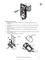
Figure 3
Tamper
Lever
A
T5
T1
B2
W9
B3
W2
B
L1
T3
B1
L2
W3
B4
R1
R2
(not visible)
T2
T6
(not visible)
T4
W5
W6
Figure 4
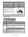
Note:
For 45° right side installation use the equivalent units on the external base as follows:
Knockouts Description Lef
t
Righ
t
Mounting Knockouts L1, L2 R1, R2
Tamper spring knockouts T1,T3 T2,T4
Tamper screw anchor T5 T6
Wiring Knockouts W5, W6 W7, W8

6 WatchOUT 315DT Installation Manual
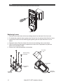
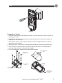
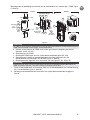
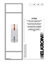
Changing Back Tamper position
The back tamper is by default secured on the right
side of the internal base (rear view). If you wish to
move it to the left side (rear view), do the following
(Figure 5):
1. Remove tamper screw 1 in order to release the
tamper from position 7.
2. Ensure tamper spring 2 rests over tamper wire
base 4.
3. Ensure plastic tamper bracket 3 rests over both
2 and 4.
4. Secure tamper screw 1 into 3 over position 6.
Figure 5
Left Side
Tamper
Right Side
Tamper
3
6
1
2
4
7
5
Notes:
1. Verify that you hear a "Click" when attaching the tamper spring to the wall.
2. For pole installation, the tamper can be moved to the bottom right-hand side of the internal base.
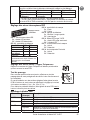
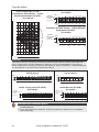
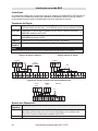
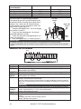
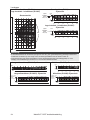
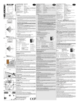
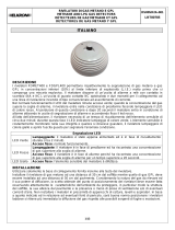
Terminal Wiring
+-
SET/
UNSET
LEDs
ENABL
AM
YEL
FR E E
ALARM
TAMPER
GREEN
FREE
DUST TEST
12VDC
N.C
N.C
WatchOUT DT - PCB
+,-
12 VDC
ALARM
N.C relay, 24VDC , 0.1A
FREE YEL
This terminal is a free pin that can be used to connect wires and EOL resistors
TAMPER
N.C switch, 24VDC , 0.1A
FREE
GREEN
This terminal is a free pin that can be used to connect wires and EOL resistors
AM
Normally closed AM relay output (
24VDC, 0.1A) indicates Anti Masking alarm or any
trouble in the detector (not including dust/dirty lens).
The Proximity AM enables receiving sabotage alerts before the detector is
damaged or masked, using both microwave channels.
Note:
When DIP8 is defined as Enabled this relay also opens momentarily when a Proximity AM
attempt occurs.
LED
ENABLE
Used to remotely control the LEDs when DIP1 is set to ON.
Enable: input is +12V OR no terminal connection
Disable: Connect the input to 0V
DUST N.O. collector max 70 mA. Indicates that the lens is dirty and requires cleaning.
TEST
Used to perform remote alarm testing to the detector by applying 0 volts to this
terminal.
Success: Alarm relay is momentary opened.
Failure: AM relay is opened
SET
/
UNSET
This input enables to control Anti-masking and LEDs operation in accordance to
the system status, Set (Arm) / Unset (Disarm).
While the system is armed this feature prevents an intruder from gaining
knowledge of the detector’s status and disables Anti-masking detection.
System Status Input Status AM Relay LEDs
Set (Arm) 0
VOf
f
Of
f
Unset (Disarm) 12V or no connection On* On**
* DIP7 is ON (Anti masking enabled)
** DIP1 is ON (LEDs enabled) and LEDs ENABLE input terminal is enabled
(+12V OR no terminal connection).

WatchOUT 315DT Installation Manual 7
EN
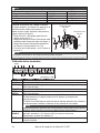
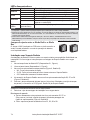
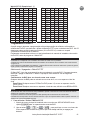
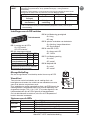
DIP Switch Settings
5
6
7
8
O
1
2
3
4
O
N
Factory Defaults
DIP 4: Anti masking Sensitivity
On: High
Off: Low
DIP 5: Detector's optics
On: Barrier / Long range
Off: Wide angle
DIP 6: Red LED /3 LED
On: Red LED only
Off: 3 LEDs
DIP 7: Anti masking operation
On: Enabled
Off: Disabled
DIP 8: Proximity AM
On: Enabled
Off: Disabled
DIP 1: LEDs operation
On: LEDs Enabled
Off: LEDs Disabled
DIP 2-3: Detection Sensitivity
Sensitivity DIP2 DIP3
Low Off Off
Mid Off On
Normal (Defaul
t
)
On Off
Maximum* On On
* In maximum sensitivity sway recognition is
disabled to achieve maximum sensitivity
Microwave Adjustment
Adjust Microwave coverage area by using the trimmer on the PCB.
MIN
MAX
Walk test
Two minutes after applying power, walk test the protected area to verify
proper operation.
For installations on uneven surfaces slide the PCB inside the internal base to
the appropriate setting according to the desired height (1.0m, 1.5m, 2.2m,
2.7m) as printed on the bottom left corner of the PCB or use the standard
swivel accessory.
For reducing the detection range, slide the PCB up
or tilt the swivel
down
.
1.00M
1.50M
2.20M
2.70M
PCB
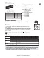
LEDs Display
LED State Description
YELLOW
Steady Indicates PIR detection
Flashing Indicates Active IR AM (Anti mask) detection
GREEN
Steady Indicates MW detection
Flashing Indicates Proximity AM detection
RED
Steady Indicates ALARM
Flashing Indicates malfunctioned communication with ProSYS (BUS
mode only)
All LEDs
Flashing (One
after another)
Unit initialization on power up
Notes:
1. DIP-Switch 1 should be in ON position to enable LED indications.
2. Only one LED is active at any one time. For example, in the case of both PIR and MW detection, either the
steady YELLOW LED or the steady GREEN LED is displayed (the first to detect), followed by the Alarm RED
3. In order to prevent the analysis of detection technologies such as PIR, Microwave, Active IR AM and
Proximity AM, set DIP Switch 6 (SW1) to ON. Only the red LED will be activated.

8 WatchOUT 315DT Installation Manual
Relay Mode / BUS Mode Jumper
J-BUS jumper (located on the PCB between the red and green
LEDs) is used to define the detector’s mode of operation as
follows:
Relay
Mode
BUS Mode
O
N
O
N
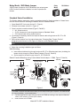
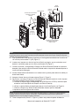
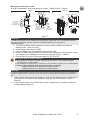
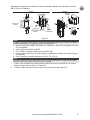
Standard Swivel Installation
The Outdoor detector packaging contains a standard swivel for flexible installation. Please follow
the instructions below for mounting the detector with the Standard Swivel:
1. Open WatchOUT front cover (Unlock C1, Figure1).
2. Release internal base (Unlock I1, Figure 2).
3. Open knockouts on external base (Figure 6, Detail B)
• W1: Wires knockout
• S1,S2: Knockouts for securing external base to Standard Swivel
• S3: External base locking screw knockout
4. On the swivel accessory remove the required swivel cable wiring knockout S2, S7 or S9
(Figure 6, Detail A).
5. Remove back tamper from the internal base (see “Changing Back Tamper Position"
paragraph) and connect it to S5 (Figure 6, Detail A) on the Standard Swivel.
Note:
Ensure that you see the engraved UP mark on the upper front face of the swivel.
6. Select the mounting installation type as follows:
Wall Mounting
a. Insert external cable wiring through knockouts S2, S7 or S9 and extract them (including the
tamper wires) through the Swivel Wires Passage (Figure 6, Detail B).
b. Secure swivel to the wall through holes S1, S3, S6 and S8.
Swivel Conduit Mounting (using Conduit Metal Swivel Adaptor – CSMA, Figure 6, Detail A)
S1
S2
S3
S9
S8
S7 S6
S5
S4
Tamper
(see Detail C)
Swivel Wires
Passage
Tamper
Spring
Holes
Ø 21 mm
Ø 16 mm
CSMA
M1
M2
M3
M4
Detail A Detail B
S1
W1
S2
S3
Snaps
Standard Swivel
Detail C
Figure 6
Note:
The CSMA is required when wall external wiring is used and protection pipe is required. The CSMA should
be ordered separately - P/N RA300SC0000A.
a. Choose the direction upon which to mount the CSMA according to the required diameter:
16mm (0.63 inches) or 21mm (0.83 inches).
b. Insert conduit to the CSMA.

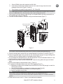
WatchOUT 315DT Installation Manual 9
EN
c. Secure CSMA to the wall through points (M1, M4).
d. Insert external cables and tamper wires from the conduit through the swivel wires
passage of the swivel (Figure 6, Detail A).
e. Secure swivel to the wall through holes S1, S3, S6 and S8.
Note:
The Tamper spring S5 (Figure 7) should make contact with the wall through the tamper spring holes M2 or
M3 on the CSMA. Make sure to hear the tamper "Click" when connecting to the wall.
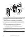
7. Insert tamper wires and external cable wiring from Standard Swivel through knockout W1 on
the external base (Figure 6, Detail B).
8. Connect the external base to the swivel using the dedicated snaps (Figure 7).
PCB
External Base
Internal Base
Angle Locking
Screw
(See Note 2)
See Detail A
Swivel to External Base
Connecting Screws
Detail A
Swivel Assy
Connecting Screw
(See Note)
Snaps
S1
W1
S2
S3
Figure 7
Note:
Do not open or close the Swivel Assy Screw since it is used for connecting the swivel parts only.
9. Secure external base to swivel with two screws fastened to knockouts S1 and S2 (Figure 7).
10. Insert the supplied angle locking screw from the external base through the angle locking screw
knockout S3 on the external base to the standard swivel (Figure 7).
11. Tilt and Rotate the Standard Swivel to the desired position. Once the Standard Swivel is in the
desired position, secure the angle locking screw.
12. Line up the internal base onto the external base. Insert all wiring cables through the internal
base.
13. Secure internal base to external base (Lock I1, Figure 2).
14. To readjust the Standard Swivel when the PCB is installed (Figure 7):
a. Bend down the black foam located below the RED LED on the PCB (enough to reach the
Swivel locking screw).
b. Use a Philips screwdriver to release the locking screw (see Figure 8).
c. Tilt and/or Rotate the Standard Swivel to the desired position.
d. Secure the angle locking screw.
Note:
When marks on the two movable parts are aligned (Figure 8), the Standard Swivel is in 0°
vertical /horizontal position. Each click from this position represents shifting of 5° in vertical / horizontal
position.
15. Close the front cover (Lock C1, Figure 1) and walk test the detector.

10 WatchOUT 315DT Installation Manual
Note:
The screw has to pass through External Base and locked to the swivel.
Figure 8
Replacing Lenses
1. Unlock the six screws that hold the lens holding sleeve from the back of the front cover.
2. To release the protective sleeve, gently push the lens from the external side of the front cover.
3. Disconnect the lens from the sleeve by gently pushing the lens clips that secure it to the
sleeve.
4. Replace the lens. Place the 4 clips of the lens into the matching holes on the sleeve.
5. Insert the protective sleeve back into place on the front cover. Pay attention to place the
sleeve over the sealing rubber.
6. Secure the 6 holding screws back to their place.
Lens Protecting
Sleeve
Sockets for
Lens Clips
Sleeve Locking
Screws
Lens Locking
Clips
Sealing Rubber
Front Cover
Locking Screw

WatchOUT 315DT Installation Manual 11
EN
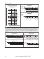
Lens Types
Wide angle lens (RL300) /
Low installation - Pet lens (RL300F) :
Top view
11
11
Feet
0
0
10
20
30 40 50
10
20
30
40
10
20
30
40
2468100121415
1
3
5
7
9
0
1
3
5
7
9
90°
Wide angle lens (RL300):
Side View
Typical
Installation
Height:
2.2m (7'2")
0
10
2468100121415
0
10
20
30 40 50
1
3
0
Feet
Meters
Feet
Low installation - Pet lens (RL300F) :
Side view
Feet
0
6
2468100121415
0
10
20
30 40 50
1
0
2
Meters
Feet
Typical
Installation
Height:
1.5m (5'3")
Note:
The detector's Pet Immunity (height of an animal, no weight limitation), is up to 70 cm (2'4"), when installing the
detector at 2.2m (7'2"). If the installation is bellow the height mentioned above, the Pet Immunity decreases
accordingly; every 10 cm (4") decrease in installation height leads to 10 cm (4") decrease in pet imunity.
Long range lens (RL300LR): Top view
246810012141618202223
0
10
20
30 40 50
60 70 75
1
0
1
0
3
3
Feet
Meters
Feet
5°
Barrier lens (RL300B): Top view
2468100121415
0
10
20
30 40 50
1
0
1
0
3
3
Feet
Meters
Feet
5°
Long range lens (RL300LR): Side view
0
10
1
3
0
2468100 1214 161820 2223
Meters
0
10
20
30 40 50
60 70 75
Feet
Typical
Installation
Height:
2.2m (7'2")
Feet
Barrier lens (RL300B): Side view
2468100121415
0
10
20
30 40 50
Feet
Meters
0
10
1
3
0
Typical
Installation
Height:
2.2m (7'2")
Feet

12 WatchOUT 315DT Installation Manual
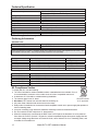
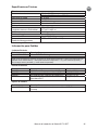
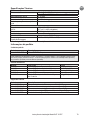
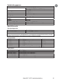
Technical Specification
Electrical
Current consumption 30mA at 12 VDC (Stand by)
42mA at 12 VDC (MAX with LED ON)
Voltage requirements 9 -16 VDC
Alarm contacts 24 VDC, 0.1A
AM contacts 24 VDC, 0.1A
Dust output Open collector 70mA max
Physical
Size: LxWxD 230 x 123 x 124mm (9 x 4.8 x 4.88 in.)
Weight 0.632 Kg (1.4lb)
Environmental
RF immunity According to EN50130-4
Operating/Storage temperature -30°C to 60°C (-22°F to 140°F)
* PIR technology is limited in rough environmental conditions.
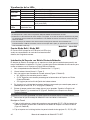
Ordering Information
Standard Units
Model Description
WatchOUT 315DT WatchOUT DT + Swivel
Note:
Each of the detectors contains a standard swivel and 3 replacement lenses (P/N engraved on the Lens) 1.7m
low installation pet (RL300F), long-range (RL300R) and barrier lens (RL300B).
Accessories Kits
Model Description Weight
RA300B WatchOUT Barrier Swivel Kit 0.1 Kg (0.23 lb)
RA300P WatchOUT Pole Adaptor Kit 0.25 Kg (0.55 lb)
RA300C WatchOUT Conduit Adaptor Kit 0.6 Kg (1.27 lb)
RA300HS WatchOUT Demo Housing - -
RA300SC WatchOUT Swivel Metal Conduit Adaptor 1Kg (2.2 lb)
Camera Option
Model Description
WatchOUT VC1 WatchOUT Camera Cover Adaptor
WatchOUT VC017 WatchOUT Narrow Camera
WatchOUT VC053 WatchOUT Wide Camera
WatchOUT VCPS WatchOUT Camera 220V Power Supply
WatchOUT VCPS WatchOUT Camera 120V Power Supply
UL Compliance Section
To comply with UL, note the following:
♦ The unit is intended for outdoor installation where unwanted alarms are tolerable. If not, it
is recommended to connect it to the trouble circuit of a listed compatible control unit.
♦ A dead zone of 5 ft should be considered during installation.
♦ The camera option is not UL listed.
♦ Disclaimer: PET feature has not been tested or verified by UL.
♦ 0.6 power factor inductive load can be used on the relays.
♦ Relay mode is intended to be connected to listed compatible control unit or power supply that provides 4
hours of standby power.
♦ It may be necessary to set detector at maximum sensitivity to achieve maximum distance.
♦ Do not connect the DUST output to a UL listed product.
♦ When the detectors are connected to the BUS of the ProSYS panel, the detectors are to be powered
from either the ProSYS (Version 7.55) panel or a listed compatible burglar alarm power supply that has
an output voltage range that does not exceed 9-16 vdc, has a minimum of 4 hrs. of standby power, and
is suitable for mercantile use.
Only P/N:
RK315DT00USB
is UL approved

WatchOUT 315DT Installation Manual 13
EN
BUS Mode Installation
Introduction
The information in this section relates to WatchOUT 315DT installation in BUS Mode only. Up to
32 BUS detectors can be installed on the ProSYS RS485 BUS, saving cabling time and enabling
remote control and diagnostics.
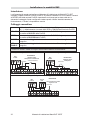
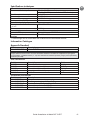
Terminal Wiring
+,-
Used for the connection of 12VDC power supply. Connect the (+) terminal to
the AUX RED and the (–) terminal to the COM BLK of the ProSYS terminals
YELLOW
Used for data communication with the ProSYS. Connect to the terminal to the
BUS YEL of the ProSYS
GREEN Used for data communication with the ProSYS. Connect to the terminal to the
BUS GRN of the ProSYS
TAMPER
Used for the wiring for tamper detection, see below
LED
ENABLE
Used for the wiring for tamper detection, see below
Note:
All terminals that are not mentioned in the table above are unused.
Cover and Back Tamper
+-
SET/
UNSET
LEDs
ENA BL E
AM
YEL
FREE
ALARM
TAMPER
GREEN
FREE
DUST TEST
COM
BLK
BUS
GRN
YEL
BUS Mode:
Cover + Back tamper wiring
BACK
TAMPER (N.C)
ProSYS
Short
AUX
RED
Cover Tamper Only
+-
SET/
UNSET
LEDs
ENAB LE
AM
YEL
FREE
ALARM
TAMPER
GREEN
FREE
DUST TEST
COM
BLK
BUS
GRN
YEL
BUS Mode:
Cover Tamper Wiring
ProSYS
Short
AUX
RED
Cover Tamper to Zone Inpu
t
+-
SET/
UNS ET
LEDs
ENA BLE
AM
YEL
FREE
ALARM
TAMPER
GREE N
FREE
DUST TEST
COM
BLK
BUS
GRN
YEL
BUS Mode:
Cover Tamper to Zone Input
ProSYS
BUS
Short
Zone
COM
Z1 Z2
Zone
Input
AUX
RED
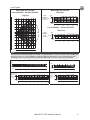
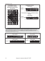
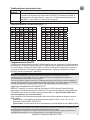
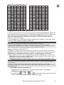
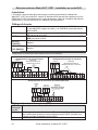
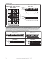
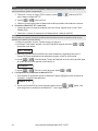
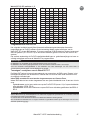
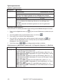
DIP Switch Settings
DIP Switch
Number
Description
1 - 5 Used to set the detector ID number. Set the ID number in the same way as for
any other ProSYS accessory (Refer to the ProSYS installation instruction
manual)
6 - 8 Not used

14 WatchOUT 315DT Installation Manual
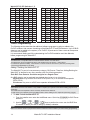
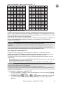
WatchOUT ID: DIP Switches 1 - 5
ID 1 2 3 4 5 ID 1 2 3 4 5
01 OFF OFF OFF OFF OFF 17 OFF OFF OFF OFF ON
02 ON OFF OFF OFF OFF 18 ON OFF OFF OFF ON
03 OFF ON OFF OFF OFF 19 OFF ON OFF OFF ON
04 ON ON OFF OFF OFF 20 ON ON OFF OFF ON
05 OFF OFF ON OFF OFF 21 OFF OFF ON OFF ON
06 ON OFF ON OFF OFF 22 ON OFF ON OFF ON
07 OFF ON ON OFF OFF 23 OFF ON ON OFF ON
08 ON ON ON OFF OFF 24 ON ON ON OFF ON
09 OFF OFF OFF ON OFF 25 OFF OFF OFF ON ON
10 ON OFF OFF ON OFF 26 ON OFF OFF ON ON
11 OFF ON OFF ON OFF 27 OFF ON OFF ON ON
12 ON ON OFF ON OFF 28 ON ON OFF ON ON
13 OFF OFF ON ON OFF 29 OFF OFF ON ON ON
14 ON OFF ON ON OFF 30 ON OFF ON ON ON
15 OFF ON ON ON OFF 31 OFF ON ON ON ON
16 ON ON ON ON OFF 32 ON ON ON ON ON
ProSYS Programming
The following section describes the additional software programming options, added to the
ProSYS software, that concern the settings of the WatcOUT DT as a BUS detector. Up to 32 BUS
detectors can be added to the system (16 in ProSYS 16) and each of them comes at the expense
of a zone in the system.
It is recommend reading and fully understanding the ProSYS Installation and User Manuals,
before programming the WatchOUT.
Notes:
The WatchOUT is compatible with the ProSYS software Version 4.xx and above.
The WatchOUT can be programmed via the U/D Software from UD Version 1.8 and above.
For maximum operation stability, it is best NOT to exceed a total of 300 meters (1000 feet) of wiring when
connecting the WatchOUT to the BUS.
Adding / Deleting the WatchOUT DT
The WatchOUT is part of a new accessory category, BUS zones. Therefore, Adding/Deleting the
WatchOUT is identical to any other accessory with the following exception:
Each BUS Zone Detector should be assigned to a Regular Zone.
Any BUS detector can be assigned to a physical wired zone or to a virtual zone.
Physical zone: Any zone on the ProSYS PCB (zones 1-8) or on a wired zone expander
(ZE08, ZE16).
Virtual zone: Any zone on a BUS zone expander defined as BZ08 or BZ16.
Notes:
Virtual BUS zones are cost effective. They enable to expand your system zones without adding physical zone
expanders.
The virtual BUS zone expander can be used only for BUS zone detectors.
To add a BUS zone expander select type BZ08 or BZ16 when adding a zone expander (Quick key [7][1][2]).
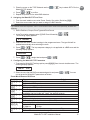
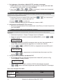
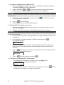
1. To Add / Delete the WatchOUT DT
1. From the installer menu enter the Add/Delete menu: Quick Key [7][1][9][5] for BUS Zones
detectors.
2. Use the
/ or / keys to position the cursor over the BUS Zone
ID number for which you want to assign (or delete) a detector.
Note:
Make sure that the detector's physical ID number is identical to the ID number you select during programming.

WatchOUT 315DT Installation Manual 15
EN
3. Place the cursor on the TYPE field and use the / key to select ODT15 for the
WatchOUT DT detector.
4. Press
/ to confirm.
5. Repeat the process for the other BUS detectors.
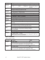
2. Assigning the WatchOUT DT to a Zone
1. From the main installer menu enter Zones: One by One option (Quick key [2][1])
2. Select the zone number that you want to assign the BUS detector.
Note:
If you defined a BUS Zone Expander, select a zone number from the virtual zones (defined by the BUS zone
expander).
3. Define Partitions, Groups, Zone Type and Zone Sound.
4. In the Termination category select [5] BUS Zone followed by
/ .
The following display appears:
Z:001 LINK TO:
ID:01 TYPE=ODT15
Z:001 LINK TO:
ID:01 TYPE=ODT15
5. Select the BUS zone number to assign to the programmed zone. The type field will be
updated automatically when selecting the zone.
6. Press
/ . The loop response category is not applicable to a BUS zone and the
following display appears:
Z:001 RESPONSE:
N/A-BUS ZONE
Z:001 RESPONSE:
N/A-BUS ZONE
7. Press
/ , assign label and press / .
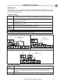
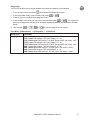
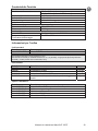
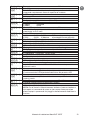
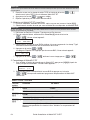
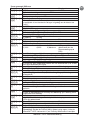
3. Configuring the WatchOUT DT Parameters
1. To access the WatchOUT settings option press [2][0][3] from the main installer menu. The
following display appears:
B-ZONE PRMS:
ZONE#=001 (M:ZZ)
B-ZONE PRMS:
ZONE#=001 (M:ZZ)
2. Select the zone that the BUS zone was assigned to and press
/ . You can
now program the WatchOUT parameters as follows:
Zones Miscellaneous: BUS Zone
Quick Keys Parameter Defaul
t
[2][0][3][zzz]
[1]
LEDS 3 LEDS
Defines the LEDS operation mode.
[2][0][3][zzz]
[1][1]
Of
f
Disables the LEDS operation.
[2][0][3][zzz]
[1][2]
Red Only
Only the Red led will operate. This option is highly recommended to avoid the
possibility that the intruder will “Learn” the detector behavior.
[2][0][3][zzz]
[1][3]
3 LEDS
All 3 LEDs will operate.
[2][0][3][zzz]
[2]
PIR Sensitivity Normal
Defines the sensitivity of the detector(MW + PIR)
[2][0][3][zzz]
[2][1]..[4]
Sensitivity Options
1) Low
2) Medium
3) Normal
4) High
[2][0][3][zzz]
[3]
MW Range Trimmer
Defines the microwave channel range. The maximum is 23m.

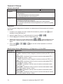
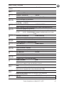
16 WatchOUT 315DT Installation Manual
Quick Keys Parameter Defaul
t
[2][0][3][zzz]
[3][1]..[7]
MW Range options
1) Minimum
2) 20%
3) 40%
4) 60%
5) 80%
6) Maximum
7) Trimmer (MW is defined
by the trimmer setting on
the PCB)
[2][0][3][zzz]
[4]
Anti-Mask sensitivity Low sensitivity
Defines the sensitivity of the active IR AM
[2][0][3][zzz]
[4][1]..[2]
Anti-Mask sensitivity option
1) Low Sensitivity 2) High Sensitivity
[2]
[
0][3][zzz]
[5]
Lens Type Wide Angle
Defines the actual Lens of the detector
[2][0][3][zzz]
[5][1]..[2]
Lens Type Options
1) Wide Angle 2) Barrier / Long Range
[2][0][3][zzz]
[6]
Anti-Mask Enable
Defines the operation of Anti Masking detection
[2][0][3][zzz]
[6][1]..[2]
Anti-Mask Options
1) Disable 2) Enable (Default)
[2][0][3][zzz]
[7]
Arm/Disarm No
Defines the operation of the LEDs anti masking detections while the detector
is armed
[2][0][3][zzz]
[7][1]
No
Active IR AM and Proximity AM (Anti masking) is enabled
LEDs behave according to the LEDs parameter definition
[2][0][3][zzz]
[7][2]
Yes
Active IR AM and Proximity AM (Anti masking) is disabled
LEDs are disabled
[2][0][3][zzz]
[8]
Proximity AM Disable
Defines the operation of the Proximity Anti Masking detection
[2][0][3][zzz]
[8][1]..[2]
Proximity AM Options
1) Disable (Default) 2) Enable
NOTE: Disable Proximity AM during heavy rain (if WatchOUT 315DT is not
sheltered) to prevent Proximity AM alerts.
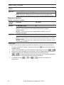
System Parameters
System: System Control
Quick Keys Parameter Default:
[1][2][36] IR AM=Tamper No
Used to determine the operation of Active IR Anti Masking detection
Yes: Active IR Anti mask detection will activate tamper alarm.
No: Active IR Anti mask detection will be regarded as trouble event.
[1][2][37] Prox AM=Tamper No
Used to determine the operation of the Proximity Anti Masking detection
Yes: Proximity Anti mask detection will activate tamper alarm.
No: Proximity Anti mask detection will be regarded as a trouble event.

WatchOUT 315DT Installation Manual 17
EN
Diagnostics
The ProSYS enables you to test parameters that reflect the operation of the detector.
1. From the main user menu press
[4] to access the Maintenance menu.
2. Enter the Installer code (or sub-installer) and press
/ .
3. Press [9] [1] to for the BUS Zones diagnostic menu.
4. Enter the digit of the zone that you want to test and then press
/ . The system will
perform the diagnostics test and a list of test parameters will appear, as indicated in the table
below.
5. Use the keys
/ / to view the diagnostics test results.
User Menu: 4) Maintenance → 9) Diagnostic → 1) BUS Zone
Quick Keys Parameter
[4][9][1][zzz] Detector Input Voltage: Display the input voltage of the detector.
PIR 1 Level: PIR channel 1 DC level. Range 0.1v - 4v
PIR 1 Noise Level: PIR channel 1 AC level. Range 0VAC (No noise) - 4VA
PIR 2 Level: PIR channel 2 DC level. Range 0.1v - 4v
PIR 2 Noise Level: PIR channel 2 AC level. Range 0VAC (No noise) - 4VA
MW 1 Level: MW channel 1 DC level Range 0.1v - 4v
MW 1 Noise Level
: MW channel 1 AC level (0VAC (No noise) - 4VAC)
MW 2 Level: MW channel 2 DC level Range 0.1v - 4v
MW 2 Noise Level: MW channel 2 AC level (0VAC (No noise) - 4VAC

18 WatchOUT 315DT Installation Manual

Manuale di installazione WatchOUT 315DT 19
IT
Indice Dei Contenuti
Installazione in modalità relé ............................................................................................... 20
Introduzione ......................................................................................................................... 20
Installazione ......................................................................................................................... 20
Considerazioni per l’installazione ....................................................................................... 20
Installazione a parete ......................................................................................................... 21
Installazione piana ............................................................................................................. 21
Installazione angolare di 45° (installazione a sinistra) ......................................................... 21
Modifica della posizione del tamper antirimozione .............................................................. 22
Cablaggio morsettiera ......................................................................................................... 22
Predisposizione Microinterruttori ........................................................................................ 23
Regolazione microonda ....................................................................................................... 23
Prova di movimento ........................................................................................................... 23
Indicatori LED ....................................................................................................................... 24
Microinterruttore Modalità Relé / BUS ................................................................................ 24
Installazione dello snodo standard ..................................................................................... 24
Installazione a parete ......................................................................................................... 24
Installazione per tubo elettrico ............................................................................................ 25
Sostituzione delle Lenti ........................................................................................................ 27
Tipologie di Lenti ................................................................................................................ 28
Caratteristiche Tecniche ....................................................................................................... 29
Informazioni per l’ordine ..................................................................................................... 29
Installazione in modalità BUS .............................................................................................. 30
Introduzione ......................................................................................................................... 30
Cablaggio morsettiera ......................................................................................................... 30
Tamper Antiapertura e Antirimozione............................................................................. 30
Solo Tamper Antiapertura .............................................................................................. 30
Tamper Antiapertura ad un Ingresso di Zona ................................................................. 30
Predisposizione microinterruttori ........................................................................................ 31
Programmazione ProSYS ..................................................................................................... 31
Aggiunta e Cancellazione del WatchOUT DT ..................................................................... 31
Configurazione dei parametri del WatchOUT DT ................................................................ 32
Parametri di Sistema ............................................................................................................ 33

20 Manuale di installazione WatchOUT 315DT
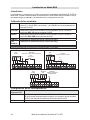
Installazione in modalità relé
Introduzione
Il rivelatore da esterno Doppia Tecnologia WatchOUT 315DT di RISCO Group è un dispositivo a
microprocessore che elabora i segnali rilevati tramite due canali all’infrarosso passivo (PIR) e due
canali a microonda (MW). Il rivelatore può funzionare come rivelatore tradizionale con uscite a
relé collegabili a qualsiasi centrale d’allarme, o come rivelatore indirizzato via BUS 485 collegato
ai sistemi ProSYS di RISCO. Quando viene collegato ai sistemi ProSYS, il rivelatore può essere
programmato e testato sia localmente che in remoto tramite tastiere LCD ProSYS e/o software di
Teleassistenza RISCO. Le istruzioni che seguono descrivono l’installazione e la configurazione
del WatchOUT 315DT sia in modalità Relé che via BUS. Per informazioni sul collegamento in
modalità BUS ProSYS, consultare il capitolo “Installazione in modalità BUS
”.
Installazione
Considerazioni per l’installazione
1m - 2.7m
(3'3" - 8'9")
Altezza di installazione: Grandangolo 15m
90° (RL300)
Note:
1. Per altezze di installazione basse, al di sotto di
1.7m ove è richiesta l’opzione di
discriminazione animali, vanno utilizzate le lenti
RL300F (muri bassi o installazione su
recinzioni).
2. La discriminazione animali (altezza
dell’animale senza limiti di peso) arriva fino a
70 cm con il rivelatore installato a 2.2m. Se
l’altezza di installazione è al di sotto di 2.2
metri la discriminazione animali si riduce
proporzionalmente. Ogni 10cm in meno
rispetto a 2.2 metri corrispondeono 10 cm in
meno di altezza dell’animale discriminato.
Se possibile, evitare di direzionare l’unità verso
oggetti in movimento (alberi ondeggianti,
cespugli, ecc.)
Mantenere una distanza
di almeno 5m (16') da
oggetti in movimento
Fuori campo di
rilevazione
5m (16')
Assicurarsi che nessun oggetto ostruisca il
campo di rilevazione dell’unità sia per la
sezione a microonda sia per quella ad
infrarossi. Prestare attenzione alla crescita di
alberi, rami e ad eventuali altre piante che con
il tempo possono coprire l’area di rilevazione.
Per quelle installazioni vicino a strade ad intenso traffico di
veicoli o oggetti oltre l’area di rilevazione desiderata, si
consiglia di regolare la sensibilità della microonda (MW) e/o
inclinare il rivelatore verso il basso.
Nota:
Inclinando il rivelatore verso il basso è possibile che la funzione di
immunità agli animali si riduca.
Per una migliore rivelazione
selezionare una posizione di
installazione in modo che
l’eventuale intruso attraversi
l’area di copertura del rivelatore
con una traiettoria di circa 45°
rispetto allo stesso.
NOTA: Con la funzione ‘Antiavvicinamento’ abilitata e il sensore installato a cielo aperto, si
raccomanda di creare un riparo sopra di esso per evitare allarmi impropri in presenza di forti
pioggie o alternativamente disabilitare la funzione.
La page est en cours de chargement...
La page est en cours de chargement...
La page est en cours de chargement...
La page est en cours de chargement...
La page est en cours de chargement...
La page est en cours de chargement...
La page est en cours de chargement...
La page est en cours de chargement...
La page est en cours de chargement...
La page est en cours de chargement...
La page est en cours de chargement...
La page est en cours de chargement...
La page est en cours de chargement...
La page est en cours de chargement...
La page est en cours de chargement...
La page est en cours de chargement...
La page est en cours de chargement...
La page est en cours de chargement...
La page est en cours de chargement...
La page est en cours de chargement...
La page est en cours de chargement...
La page est en cours de chargement...
La page est en cours de chargement...
La page est en cours de chargement...
La page est en cours de chargement...
La page est en cours de chargement...
La page est en cours de chargement...
La page est en cours de chargement...
La page est en cours de chargement...
La page est en cours de chargement...
La page est en cours de chargement...
La page est en cours de chargement...
La page est en cours de chargement...
La page est en cours de chargement...
La page est en cours de chargement...
La page est en cours de chargement...
La page est en cours de chargement...
La page est en cours de chargement...
La page est en cours de chargement...
La page est en cours de chargement...
La page est en cours de chargement...
La page est en cours de chargement...
La page est en cours de chargement...
La page est en cours de chargement...
La page est en cours de chargement...
La page est en cours de chargement...
La page est en cours de chargement...
La page est en cours de chargement...
La page est en cours de chargement...
La page est en cours de chargement...
La page est en cours de chargement...
La page est en cours de chargement...
La page est en cours de chargement...
La page est en cours de chargement...
La page est en cours de chargement...
La page est en cours de chargement...
La page est en cours de chargement...
La page est en cours de chargement...
La page est en cours de chargement...
La page est en cours de chargement...
La page est en cours de chargement...
La page est en cours de chargement...
La page est en cours de chargement...
La page est en cours de chargement...
La page est en cours de chargement...
La page est en cours de chargement...
La page est en cours de chargement...
La page est en cours de chargement...
La page est en cours de chargement...
La page est en cours de chargement...
La page est en cours de chargement...
La page est en cours de chargement...
La page est en cours de chargement...
La page est en cours de chargement...
La page est en cours de chargement...
La page est en cours de chargement...
La page est en cours de chargement...
La page est en cours de chargement...
La page est en cours de chargement...
La page est en cours de chargement...
La page est en cours de chargement...
La page est en cours de chargement...
La page est en cours de chargement...
La page est en cours de chargement...
-
 1
1
-
 2
2
-
 3
3
-
 4
4
-
 5
5
-
 6
6
-
 7
7
-
 8
8
-
 9
9
-
 10
10
-
 11
11
-
 12
12
-
 13
13
-
 14
14
-
 15
15
-
 16
16
-
 17
17
-
 18
18
-
 19
19
-
 20
20
-
 21
21
-
 22
22
-
 23
23
-
 24
24
-
 25
25
-
 26
26
-
 27
27
-
 28
28
-
 29
29
-
 30
30
-
 31
31
-
 32
32
-
 33
33
-
 34
34
-
 35
35
-
 36
36
-
 37
37
-
 38
38
-
 39
39
-
 40
40
-
 41
41
-
 42
42
-
 43
43
-
 44
44
-
 45
45
-
 46
46
-
 47
47
-
 48
48
-
 49
49
-
 50
50
-
 51
51
-
 52
52
-
 53
53
-
 54
54
-
 55
55
-
 56
56
-
 57
57
-
 58
58
-
 59
59
-
 60
60
-
 61
61
-
 62
62
-
 63
63
-
 64
64
-
 65
65
-
 66
66
-
 67
67
-
 68
68
-
 69
69
-
 70
70
-
 71
71
-
 72
72
-
 73
73
-
 74
74
-
 75
75
-
 76
76
-
 77
77
-
 78
78
-
 79
79
-
 80
80
-
 81
81
-
 82
82
-
 83
83
-
 84
84
-
 85
85
-
 86
86
-
 87
87
-
 88
88
-
 89
89
-
 90
90
-
 91
91
-
 92
92
-
 93
93
-
 94
94
-
 95
95
-
 96
96
-
 97
97
-
 98
98
-
 99
99
-
 100
100
-
 101
101
-
 102
102
-
 103
103
-
 104
104


Risco WatchOUT XTreme 315DT Installation Instructions Manual
- Taper
- Installation Instructions Manual
dans d''autres langues
- italiano: Risco WatchOUT XTreme 315DT
- English: Risco WatchOUT XTreme 315DT
- español: Risco WatchOUT XTreme 315DT
- Nederlands: Risco WatchOUT XTreme 315DT
- português: Risco WatchOUT XTreme 315DT
Documents connexes
-
Risco watchout 312PR Installation Instructions Manual
-
Ris RWT312PR800A Manuel utilisateur
-
-
-
-
-
-
-
-
Risco Industrial LuNAR RK200DTG3 Guide d'installation
Autres documents
-
 Elkron IR600FC/RF Guide d'installation
-
 ATSUMI ELECTRICS Atsumi TriWatcher SIR10SA Outdoor PIR Detector Technical Manual
-
 Elkron SP900/10 Guide d'installation
-
Comelit RF2PIRW Technical Manual
-
 Elkron DT600 Guide d'installation
-
 Elkron IRA 15P Guide d'installation
-
ADEMCO 998mx Installation Instructions Manual
-
AVS Electronics JET DT Manuel utilisateur
-
 Elkron FDMET400 Guide d'installation
-
 Elkron TT19AM Guide d'installation


