
1
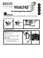
Dual Technology Outdoor Detector
Introduction
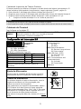
RISCO Group's Dual Technology Outdoor detector, WatchU, is a unique detector with signal
processing based on two Passive Infrared (PIR) channels and two Microwave (MW) channels.
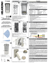
Mounting Considerations
Wall Mount Installation
Note:
The installation knockouts numbering are marked on the
back plate.
1. Open WatchU front cover
(unlock C1, Figure 1).
2. Release internal base (unlock I1, Figure 2).
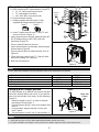
3. Select mounting installation as follows:
Flat Mounting:
Open knockouts on external base (Figure 3).
B1 - B4: Wall mounting knockouts
T1: Back tamper knockout
W2 / W3: wires entry knockouts
Figure 1
Figure 2
Out of
Detection Range
Keep distance of
minimum 5m (16')
from moving objects
5m (16')
C1
I1

2
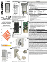
45° angle Mounting (Left side mounting)
a. Open knockouts on external base (Figure 3)
L1, L2: Left mounting knockouts
T3: Left tamper knockout
W5 / W6: Wire entry knockouts
b. Remove tamper spring.
c. Replace tamper bracket (Item 1) with
supplied flat tamper bracket (Item 2).
Item 1 Item 2
d. Insert Tamper lever B onto T5 and T3 and
secure screw A (Figure 3).
4. Insert external wires through external base W2,
W3 (Flat Mounting) or W5, W6 (Left
side
mounting) (Figure 3).
5. Secure external base to the wall.
6. Insert external wires and tamper wires through
internal base (Figure4).
7. Secure internal base to external base (lock I1,
Figure2).
8. Close the front cover (Lock C1, Figure1) after
wiring and setting DIP switches.
9. Walk test the detector.
Figure 3
Figure 4
Note:
For 45° right side installation use the equivalent units on the external base as follows:
Knockouts Description
Left Right
Mounting Knockouts L1, L2 R1, R2
Tamper spring knockouts T1,T3 T2,T4
Tamper screw anchor T5 T6
Wiring Knockouts W5, W6 W7, W8
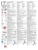
Changing Back Tamper position
The back tamper is by default secured on the right
side of the internal base (rear view). If you wish to
move it to the left side (rear view), do the following
(Figure 5):
1. Remove tamper screw 1 in order to release
the tamper from position 7.
2. Ensure tamper spring 2 rests over tamper wire
base 4.
3. Ensure plastic tamper bracket 3 rests over
both 2 and 4.
4. Secure tamper screw 1 into 3 over position 6.
Figure 5
Notes:
1. Verify that you hear a "Click" when attaching the tamper spring to the wall.
2. For pole installation, the tamper can be moved to the bottom right-hand side of the internal base.
Tamper
Lever
A
T5
T1
B2
W9
B3
W2
B
L1
T3
B1
L2
W3
B4
R1
R2
(not visible)
T2
T6
(not visible)
T4
W5
W6
Left Side
Tamper
Right Side
Tamper
3
6
1
2
4
7
5

3
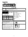
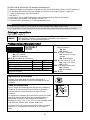
Terminal Wiring
LED
ENABLE
Used to remotely control the LEDs when DIP1 is set to ON.
Enable: input is +12V OR no terminal connection
Disable: Connect the input to 0V
DIP Switch Settings
DIP 1: LEDs operation
On: LEDs Enabled
Off: LEDs Disabled
DIP 2-3: Detection Sensitivity
Sensitivity DIP2 DIP3
Low Off Off
Mid Off On
Normal
(Default)
On Off
Maximum* On On
* In maximum sensitivity sway recognition is
disabled to achieve maximum sensitivity
DIP 4: Anti masking Sensitivity
On: High
Off: Low
DIP 5: Detector's optics
On: Barrier / Long range
Off: Wide angle
DIP 6: Red LED /3 LED
On: Red LED only
Off: 3 LEDs
DIP 7: Anti masking operation
On: Enabled
Off: Disabled
DIP 8: N/A
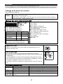
Microwave Adjustment
Adjust Microwave coverage area by using the
trimmer on the PCB.
MIN
MAX
Walk test
Two minutes after applying power, walk test
the protected area to verify proper operation.
For installations on uneven surfaces slide the
PCB inside the internal base to the
appropriate setting according to the desired
height (1.0m, 1.5m, 2.2m, 2.7m) as printed on
the bottom left corner of the PCB.
1.00M
1.50M
2.20M
2.70M
PCB

4
LEDs Display
LED State Description
YELLOW
Steady Indicates PIR detection
Flashing Indicates AM (Anti mask) detection
GREEN
Steady Indicates MW detection
RED
Steady Indicates ALARM
All LEDs
Flashing (One
after another)
Unit initialization on power up
Notes:
1. DIP-Switch 1 should be in ON position to enable LED indications.
2. Only one LED is active at any one time. For example, in the case of both PIR and MW detection, either the
steady YELLOW LED or the steady GREEN LED is displayed (the first to detect), followed by the Alarm RED
LED.
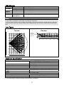
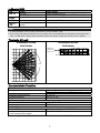
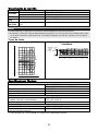
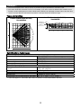
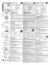
Lens Types
Wide angle lens (RL300) /
Top view
Wide angle lens (RL300):
Side View
Technical Specification
Electrical
Current consumption 45mA at 12 VDC (Stand by)
70mA at 12 VDC (MAX with LED ON)
Voltage requirements 9 -16 VDC
Alarm contacts 24 VDC, 0.1A
AM contacts 24 VDC, 0.1A
Physical
Size:
LxWxD
220 x 115 x 123mm (8.7 x 4.5 x 4.85 in.)
Weight 0.632 Kg (1.4lb)
Environmental
RF immunity (30MHz to 2GHz): 40V/m
Operating/Storage temperature -30°C to 60°C (-22°F to 140°F)
* PIR technology is limited in rough environmental conditions.
11
11
Feet
0
0
10
20
30 40 50
10
20
30
40
10
20
30
40
2468100121415
1
3
5
7
9
0
1
3
5
7
9
90°
Typical
Installation
Height:
2.2m (7'2")
0
10
2468100121415
0
10
20
30 40 50
1
3
0
Feet
Meters
Feet

5
Introduzione
Il rivelatore da esterno Doppia Tecnologia WatchU di RISCO Group è un dispositivo a
microprocessore che elabora i segnali rilevati tramite due canali all’infrarosso passivo (PIR) e due
canali a microonda (MW).
Considerazioni per l’installazione
[Vedi pagina 1]
Installazione a parete
[Vedi Figure 1-4, pagine 1-2]
Nota:
I numeri di riferimento dei fori a sfondare per
l’installazione sono marcati sulla base posteriore.
1. Aprire il coperchio frontale del WatchOUT.
(Svitare C1, figura 1).
2. Sganciare la base interna (svitare I1, fig. 2).
3. Selezionare l’altezza di installazione come
segue:
Installazione piana
Aprire i fori a sfondare della base esterna (fig. 3)
B1 - B4: Fori a sfondare per installazione
a parete.
T1: Foro a sfondare per il tamper
antirimozione
W2 / W3: Fori a sfondare per il
passaggio cavi
Installazione angolare di 45°
(installazione a sinistra)
a. Aprire i fori a sfondare della base esterna
(fig. 3)
L1, L2 : Fori a sfondare per lato
sinistro
T3: Foro a sfondare per tamper lato
sinistro
b. W5 / W6: Fori a sfondare per passaggio
caviRimuovere la molla del tamper
c. Sostituire la staffa (Item 1) con l’altra
fornita (Item 2).
Item 1 Item 2
d. Inserire la leva B del tamper in T5 e T3 e
stringere la vite A (figura 3)
4. Inserire I cavi esterni attraverso la base
esterna W2, W3 (Installazione piana) o
W5,
W6 (Installazione a sinistra) (figura 3).
5. Fissare la base esterna alla parete.
6. Inserire i cavi esterni e i cavi del tamper
attraverso la base interna. (figura 4).
7. Fissare la base interna a quella esterna
(bloccare I1, figura 2).
8. Chiudere il coperchio frontale (bloccare
C1, figura 1) dopo aver cablato l’unità e
predisposto i microinterruttori.a.
Nota:
Per installazioni a 45° lato destro usare le equivalenti predisposizioni sulla base esterna come segue:
Descrizione fori a sfondare Sinistra Destra
Fori a sfondare per il fissaggio della base L1, L2 R1, R2
Foro a sfondare per la molla del tamper T1,T3 T2,T4
Punto di fissaggio vite tamper T5 T6
Fori a sfondare per passaggio cavi W5, W6 W7, W8

6
Modifica della posizione del tamper antirimozione
Di fabbrica il tamper antirimozione è fissato sul lato destro della base interna (Vista Posteriore).
Se si desidera spostarlo nella parte sinistra, procedere come segue (figura 5, pagina 2):
1. Svitare la vite tamper 1 per rimuoverlo d
2. alla posiz. 7.
3. Assicurarsi che la molla 2 del tamper resti posizionata sulla base 4 del tamper.
4. Assicurarsi che la staffa 3 del tamper resti tra 2 e 4.
5. Fissare la vite 1 del tamper in 3 sulla predisposizione 6.
Note:
1. Verificare che si senta un "Click" quando la molla del tamper viene spinta contro il muro.
2. Per l’installazione su palo il tamper può essere spostato nella parte inferiore destra della base interna.
Cablaggio morsettiera
[Vedi Figura, pagina 3]
LED
ENABLE
Ingresso usato per controllare da remoto i LED quando il microint. 1 è in ON.
LED abilitati: Tensione +12V presente o morsetto non connesso
LED disabilitati: 0V presente all’ingresso
Predisposizione Microinterruttori
I
MIC 4: Sensibilità Anti-
Mascheramento
On: Alta
Off: Bassa
MIC 5: Ottica Rivelatore
On: Barriera / Lunga
portata
Off: Grandangolo
MIC 6: LED Rosso o 3 LED
On: Solo LED rosso
Off: 3 LED
MIC 7: Antimascheramento
On: Abilitato
Off: Disabilitato
MIC 8: N/A
MIC 1: Predisposizione LED
On: LED abilitati
Off: LED disabilitati
MIC 2-3: Sensibilità di rilevazione
Sensibilità MIC2 MIC3
Bassa Off Off
Media Off On
Normale (Default) On Off
Massima * On On
* Con sensibilità massima, la SRT è disabilitata per avere la
massima sensibilità
Regolazione microonda
Regolare la portata della microonda utilizzando il
potenziometro posizionato sulla scheda elettronica del
rivelatore.
MIN
MAX
Prova di movimento
Dopo 2 minuti dall’alimentazione del sensore, effettuare
una prova di movimento all’interno dell’area protetta e
verificare il buon funzionamento e la copertura del
rivelatore.
Per regolare la copertura del sensore muovere la scheda
elettronica interna del sensore per la predisposizione
appropriata in funzione dell’altezza di installazione
desiderata (1.0m, 1.5m, 2.2m, 2.7m) come stampato nella
parte inferiore sinistra della scheda elettronica.
Per ridurre l’area di copertura spostare in alto la scheda
elettronica o, se utilizzato, muovere lo snodo verso il
basso.
1.00M
1.50M
2.20M
2.70M
PCB

7
Indicatori LED
LED Stato Descrizione
GIALLO
Acceso Indica rilevazione PIR
Lampeggiante Indica Antimascheramento sull'IR Attivo (AM)
VERDE
Acceso Indica rilevazione MW
ROSSO
Acceso Indica ALLARME
TUTTI I
LED
Lampeggiante (uno alla
volta)
Inizializzazione dell’unità all’accensione
Note:
1. Il microinterruttore 1 deve essere posizionato su ON per abilitare i LED.
2. Solo un LED alla volta può illuminarsi. Per esempio, nel caso di attivazione di entrambe le tecnologie PIR e
MW, o il LED giallo o quello verde si illumina (il primo che rileva), seguito poi dal LED rosso di allarme.
Tipologie di Lenti
Grandangolo (RL300)
Vista dall’alto
Grandangolo (RL300):
Vista laterale
Altezza di
installazione
tipica 2.2m
2468100121415
1
3
0
Metri
Caratteristiche Tecniche
Elettriche
Assorbimento di corrente 30mA a 12 Vcc (a riposo)
42mA a 12 Vcc (max. con LED illuminati)
Requisiti di alimentazione 9 -16 Vcc
Contatti di Allarme 24 Vcc, 0.1 A
Contatti Antimascheramento 24 Vcc, 0.1 A
Fisiche
Dimensioni LxWxD 230 x 123 x 123mm
Peso 0.632 Kg
Ambientali
Immunità RF Conforme alla normativa EN50130-4
Temperatura di
Funzionamento/Stoccaggio
Da -30°C a 60°C
* La tecnologia di rilevazione PIR è limitata in condizioni ambientali critiche.
1
1
1
1
2468
1
0
0
1
2
1
4
1
5
1
3
5
7
9
0
1
3
5
7
9
90°

8
Introducción
El detector Exterior de Doble Tecnología de RISCO Group, WatchU, es un detector único con
tratamiento de señal basado en dos canales Infrarrojos Pasivos (PIR) y en dos canales de
Microondas (MW).
Consideraciones de Montaje
[Véase la página 1]
Instalación de Montaje en Pared
[Ver figuras 1–4 en las páginas 1–2]
Nota:
Los números pre-marcados de instalación están
señalados en la chapa posterior.
1. Abra la tapa delantera del WatchOUT
(abra C1, Figura 1).
2. Libere la base interna (abra I1, Figura 2).
3. Seleccione la instalación de montaje como
sigue:
Montaje Plano:
Abra los agujeros pre-marcados en la base
externa (Figura 3).
B1 - B4: Agujeros pre-marcados de
montaje en pared
T1: Agujero pre-marcado del tamper
trasero
W2 / W3: Agujeros pre-marcados para
entrada de cables
Montaje en ángulo de 45° (montaje del
lado izquierdo)
a. Abra los agujeros pre-marcados en la
base externa (Figura 3)
L1, L2: Agujeros pre-marcados de
montaje del lado izquierdo
T3: Agujero pre-marcado del tamper
izquierdo
W5 / W6: Agujeros pre-marcados para
entrada de cables
b. Quite el resorte del tamper
c. Reemplace la abrazadera del tamper
(Ítem 1) con la abrazadera plana
suministrada (Ítem 2).
Ítem 1 Ítem 2
d. Inserte la palanca del tamper B en T5 y
T3 y apriete el tornillo A (Figura 3)
4. Inserte los cables externos a través de la
base externa W2, W3 (montaje plano) o
W5, W6 (montaje lado izquierdo) (Figura 3)
5. Asegure la base externa a la pared.
6. Inserte los cables externos y los cables del
tamper a través de la base interna (Figura
4).
7. Asegure la base interna a la base externa
(cierre I1, Figura 2).
8. Cierre la tapa delantera (cierre C1, Figura
1) después de cablear y configurar los
interruptores DIP.
9. Haga una prueba de movimiento del
detector.
Nota:
Para la instalación del lado derecho a 45° use las unidades equivalentes en la base externa como sigue:
Descripción agujeros pre-marcados Izquierda Derecha
Agujeros de montaje L1, L2 R1, R2
Agujeros del resorte del tamper T1,T3 T2,T4
Anclaje del tornillo del tamper T5 T6
Agujeros cableado W5, W6 W7, W8

9
Cambiando la posición del Tamper Posterior
El tamper posterior por defecto se asegura en el lado derecho de la base (vista posterior). Si
desea moverlo al lado izquierdo (vista posterior), haga lo siguiente (Figura 5, pagina 2):
1. Quite el tornillo 1 del tamper para liberar el tamper de la posición 7.
2. Asegúrese que el resorte 2 del tamper está asentado sobre la base del cable del tamper 4.
3. Asegúrese que la abrazadera de plástico del tamper 3 esté asentada en el 2 y 4.
4. Asegure el tornillo del tamper 1 en el 3 sobre la posición 6.
Notas:
1. Asegúrese que escucha un "clic" al fijar el resorte del tamper a la pared.
2. Para instalación en poste, el tamper puede moverse a la parte inferior del lado derecho de la base interna.
Cableado del Terminal
[ver la figura en la página 3]
LED
ENABLE
Usado para controlar remotamente los LEDs cuando el DIP1 está puesto a ON.
Activado: entrada de +12V O sin conexión al terminal
Desactivado: conectar la entrada a 0V
Configuración del Interruptor DIP
DIP 1: Operación de los LEDs
On: LEDs Activados
Off: LEDs Desactivados
DIP 2-3: Sensibilidad de Detección
Sensibilidad DIP2 DIP3
Baja Off Off
Media Off On
Normal (Predeterm.) On Off
Máxima* On On
* En la máxima sensibilidad el reconocimiento de
oscilación se desactiva para alcanzar el máximo de
sensibilidad
DIP 4: Sensibilidad Anti-
enmascaramiento
On: Alta
Off: Baja
DIP 5: Óptica del detector
On: Barrera / Largo alcance
Off: Gran angular
DIP 6: LED Rojo / 3 LED
On: Sólo LED rojo
Off: 3 LEDs
DIP 7: Funcionamiento Anti-
enmascaramiento
On: Activado
Off: Desactivado
DIP 8: N/A
Ajuste de Microondas
Ajuste el área de cobertura del Microondas usando el
potenciómetro de la PCB (placa de circuito impreso).
MIN
MAX
Prueba de movimiento
Dos minutos después de aplicar alimentación, hacer la
prueba de movimiento en el área protegida para
verificar su correcto funcionamiento.
Para instalaciones en superficies desniveladas, deslice
el PCB dentro de la base interna al ajuste apropiado
según la altura deseada (1.0m, 1.5m, 2.2m, 2.7m) como
está impreso en la esquina inferior izquierda del PCB o
use el accesorio de rótula giratoria estándar.
Para reducir el rango de detección, deslice el PCB hacia
arriba.
Predeterminado
en Fábrica
1.00M
1.50M
2.20M
2.70M
PCB

10
Visualización de los LEDs
LED Estado Descripción
YELLOW
Constante Indica detección PIR
Parpadea Indica detección AM (Anti-enmascaramiento)
GREEN
Constante Indica detección MW
RED
Constante Indica ALARMA
Todos
los LEDs
Parpadean (uno después de
otro)
Inicialización de la unidad al encender.
Notas:
1. El interruptor DIP 1 debe estar en la posición ON para habilitar las indicaciones del LED.
2. Solamente un LED está activo al mismo tiempo. Por ejemplo, en el caso de detección simultánea PIR y MW,
se visualiza constante el LED AMARILLO o el VERDE (el primero que detecta), seguido por el LED ROJO
de Alarma.
Tipos de Lente
Lente gran angular (RL300)
Lente gran angular (RL300):
Vista lateral
Especificaciones Técnicas
Eléctrica
Consumo de corriente 45mA a 12 VDC (en reposo)
70mA a 12 VDC (máx. con LED ON)
Requisitos de voltaje 9 -16 VDC
Contactos de alarma 24 VDC, 0.1A
Contactos AM 24 VDC, 0.1A
Física
Tamaño:
Longitud x Anchura x Profundidad
220 x 115 x 123mm
(8.7 x 4.5 x 4.85 in.)
Peso 0.632 Kg (1.4lb)
Medioambiental
Inmunidad a RF (30MHz a 2GHz): 40V/m
Temperatura de
Operación/Almacenamiento
-30°C a 60°C (-22°F a 140°F)
* La tecnología PIR se ve limitada en condiciones ambientales severas.
11
11
0
0
10
20
30 40 50
10
20
30
40
10
20
30
40
2468100121415
1
3
5
7
9
0
1
3
5
7
9
90°
0
10
2468100121415
0
10
20
30 40 50
1
3
0
Pies
Meters
Pies
Instalación
Típica
Altura :
2.2 m (7'2")

11
Introduction
Le détecteur extérieur DT, WatchU de RISCO Group est un détecteur unique en son genre, doté
d'un traitement de signaux qui repose sur deux canaux à infrarouge passif (IRP) et de deux
canaux micro-ondes (MW).
Conditions de montage
[Voir page 1]
Installation murale
[voir les Figures 1 à 4 sur les pages 1-2]
Remarque :
Pour faciliter l'installation, les pastilles pré-percées prévues à
cet effet sont numérotées sur la paroi arrière de l'appareil.
1. Ouvrez le couvercle du WatchOUT. (devissez en
C1, figure 1).
2. Dégagez le socle interne (devissez en I1, figure 2).
3. Choisissez le mode d'installation comme suit
Montage à plat :
a. Percez les pastilles pré-percées du socle externe
(figure 3).
B1-B4 : pastilles pré-percées pour
assemblage mural.
T1 : pastille pré-percée de l'autoprotection
arrière.
W2 / W3 : entrées pré-percées pour fils
électriques.
Montage à 45° (montage sur côté gauche)
a. Percez les pastilles pré-percées du socle
externe (figure 3).
L1, L2 : pastilles pré-percées pour montage
à gauche
T3 : pastille pré-percée de l'autoprotection
arrière.
W5 / W6 : entrées pré-percées pour fils
électriques
b. Retirez le ressort de
l'autoprotection.
c. Remplacez le crochet
d'autoprotection 1 par le crochet
d'autoprotection plat fourni 2.
1
2
d. Insérez la languette
d'autoprotection B aux endroits
marqués T5 et T3, ensuite
serrez la vis A (figure 3).
4. Introduisez les fils électriques
extérieurs par le socle externe en
W2, W3. (figure 3).
5. Fixez le socle externe de l'appareil
au mur.
6. Faites passer les fils électriques
externes et d'autoprotection dans
le socle interne (figure 4).
7. Fixez le socle interne au socle
externe (bloquez en I1, figure 2).
8. Fermez le couvercle (bloquez en
C1, Figure 1) après avoir câblé et
réglé les micro-interrupteurs DIP.
9. Effectuez un test de passage avec
le détecteur.
Remarque :
Pour une installation à 45° sur côté droit, utilisez les pièces équivalentes du socle externe comme suit :
Désignation des pastilles pré-percées Gauche Droit
Pastilles pré-percées pour montage L1, L2 R1, R2
Pastilles pré-percées du ressort de l'autoprotection T1,T3 T2,T4
Vis de montage de l'autoprotection T5 T6
Changement de position de l'autoprotection arrière
L'autoprotection arrière est, par défaut, fixée sur le côté droit du socle interne (vue arrière). Si
vous souhaitez la déplacer sur le côté gauche (vue arrière), procédez comme suit (Fig. 5, Pg 2 )
1. Retirez la vis d'autoprotection 1 pour dégager l'autoprotection de la position 7.
2. Assurez-vous que le ressort de l'autoprotection 2 repose bien sur la base de câblage 4 de
l'autoprotection.
3. Vérifiez que le crochet en plastique 3 de l'autoprotection repose bien sur les points 2 et 4.
4. Serrez la vis d'autoprotection 1 dans la pièce 3 en la faisant passer par la position 6.

12
Remarques:
1. Vous entendrez un "Clic" en fixant le ressort de l'autoprotection au mur.
2. Pour l'installation sur un mât, l'autoprotection peut être déplacée vers le côté inférieur droit du socle interne.
Câblage de la borne de conexión
[Voir la figure à la page 3]
LED
ACTIVE
Pour le contrôle à distance des diodes LED quand le micro-interrupteur DIP1 est
en position de marche (ON).
LED Activée : alimentation +12V OU pas de connexion de la borne de connexion
LED Désactivée : mettre la borne à 0V.
Réglage des micro-interrupteurs DIP
DIP 1 : fonctionnement des LED.
On : diodes LED activées.
Off : diodes LED désactivées
DIP 2-3 : sensibilité de détection
Sensibilité DIP2 DIP3
Faible Off Off
Moyenne Off On
Normale
(par défaut)
On Off
Maximum* On On
* En sensibilité maximum, l'option de
reconnaissance des objets oscillants est
désactivée pour une sensibilité optimale.
DIP 4 : sensibilité Anti-masque
On : Elevé
Off : Faible
DIP 5 : optique du détecteur
On : Barrière / Longue portée
Off : grand angle
DIP 6 : diode LED rouge/ 3 LED
On : diode LED rouge seulement.
Off : 3 diodes LED
DIP 7 : fonctionnement Anti-masque
On : Activé
Off : Désactivé
DIP 8 : N/A
Réglage Micro-onde
Réglez la couverture micro-onde à l'aide du potentiomètre qui se
trouve sur la carte PCB.
MIN
MAX
Test de passage
Deux minutes après la mise sous tension, effectuez un test de
passage dans la zone protégée afin de vérifier le bon fonctionnement
de l'installation.
En cas d'installation sur des surfaces inégales, faites glisser la carte
PCB à l'intérieur du socle interne en effectuant le réglage qui convient
à la hauteur souhaitée (1,0m, 1,5m, 2,2m, 2,7m) .
Pour réduire la portée de détection, faites glisser la carte PCB vers le
haut.
Affichage à diodes LED
LED Etat (allumage) Description
JAUNE Continu Désigne une détection IRP.
Clignotant Désigne une détection AM (Anti-masquage).
VERT Continu Désigne une détection MW.
ROUGE Continu Indique une ALARME.
Toutes les
diodes LED
Clignotant (l'une après
l'autre)
Initialisation de l'appareil à la mise sous tension.
1.00M
1.50M
2.20M
2.70M
PCB

13
Remarques :
1. Le micro-interrupteur DIP 1 doit se trouver en position ON pour permettre les indications LED.
2. Une seule diode LED est active à la fois. Par exemple, si les deux canaux de détection IRP et MW sont en
fonction, seule la diode jaune ou seule la diode verte s'affichera en allumage constant (selon celui des deux
canaux qui aura détecté l'évènement en premier), suivie par diode LED d'alarme rouge.
Types de lentilles
Lentille Grand angle (RL300) /
Vue aérienne
Lentille Grand angle (RL300):
Vue latérale
Spécifications techniques
Caractéristiques électriques
Consommation électrique 45mA à 12 VCC (en veille)
70 à 12 VCC (max. avec diodes LED allumées)
Conditions de tension requises 9 -16 VCC
Contacts d'alarme 24 VCC, 1A
Contacts AM 24 VCC, 0.1A
Caractéristiques physiques
Dimensions :
L x l x P
220 x 115 x 123mm
(8.7 x 4.5 x 4.85 in.)
Poids 0,632 Kg (1.4lb)
Caractéristiques environnementales
Immunité RF (30MHz to 2GHz): 40V/m
Température de fonctionnement/ stockage De -30°C à 60°C (-22°F à 140°F)
* La technologie IRP est limitée dans des conditions environnementales difficiles.
11
11
Feet
0
0
10
20
30 40 50
10
20
30
40
10
20
30
40
2468100121415
1
3
5
7
9
0
1
3
5
7
9
90°
0
10
2468100121415
0
10
20
30 40 50
1
3
0
Feet
Meters
Feet
Installation
caractéristique
Hauteur :
2,2 m (7'2")

14
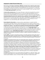
Standard Limited Product Warranty
RISCO Ltd., its subsidiaries and affiliates (“Risco") guarantee Risco’s hardware products to be
free from defects in materials and workmanship when used and stored under normal conditions
and in accordance with the instructions for use supplied by Risco, for a period of (i) 24 months
from the date of connection to the Risco Cloud (for cloud connected products) or (ii) 24 months
from production (for other products which are non-cloud connected), as the case may be (each,
the “Product Warranty Period” respectively).
Contact with customers only. This Product Warranty is solely for the benefit of the customer
who purchased the product directly from Risco, or from any authorized distributor of Risco.
Nothing in this Warranty obligates Risco to accept product returns directly from end users that
purchased the products for their own use from Risco’s customer or from any installer of Risco, or
otherwise provide warranty or other services to any such end user. Risco customer shall handle
all interactions with its end users in connection with the Warranty, inter alia regarding the
Warranty. Risco’s customer shall make no warranties, representations, guarantees or statements
to its customers or other third parties that suggest that Risco has any warranty or service
obligation to, or any contractual privy with, any recipient of a product.
Return Material Authorization. In the event that a material defect in a product shall be
discovered and reported during the Product Warranty Period, Risco shall, at its option, and at
customer's expense, either: (i) accept return of the defective Product and repair or have repaired
the defective Product, or (ii) accept return of the defective Product and provide a replacement
product to the customer. The customer must obtain a Return Material Authorization (“RMA”)
number from Risco prior to returning any Product to Risco. The returned product must be
accompanied with a detailed description of the defect discovered (“Defect Description”) and
must otherwise follow Risco’s then-current RMA procedure in connection with any such return. If
Risco determines in its reasonable discretion that any Product returned by customer conforms to
the applicable warranty (“Non-Defective Products”), Risco will notify the customer of such
determination and will return the applicable Product to customer at customer’s expense. In
addition, Risco may propose and assess customer a charge for testing and examination of Non-
Defective Products.
Entire Liability. The repair or replacement of products in accordance with this warranty shall be Risco’s
entire liability and customer’s sole and exclusive remedy in case a material defect in a product shall be
discovered and reported as required herein. Risco’s obligation and the Warranty are contingent upon the full
payment by customer for such Product and upon a proven weekly testing and examination of the product
functionality.
Limitations. The Product Warranty is the only warranty made by Risco with respect to the Products. The
warranty is not transferable to any third party. To the maximum extent permitted by applicable law, the
Product Warranty does not apply and will be void if: (i) the conditions set forth above are not met
(including, but not limited to, full payment by customer for the product and a proven weekly testing and
examination of the product functionality); (ii) if the Products or any part or component thereof: (a) have
been subjected to improper operation or installation; (b) have been subject to neglect, abuse, willful damage,
abnormal working conditions, failure to follow Risco’s instructions (whether oral or in writing); (c) have
been misused, altered, modified or repaired without Risco’s written approval or combined with, or installed
on products, or equipment of the customer or of any third party; (d) have been damaged by any factor
beyond Risco’s reasonable control such as, but not limited to, power failure, electric power surges, or
unsuitable third party components and the interaction of software therewith or (e) any delay or other failure
in performance of the product attributable to any means of communications, provided by any third party
service provider (including, but not limited to) GSM interruptions, lack of or internet outage and/or
telephony failure.
BATTERIES ARE EXPLICITLY EXCLUDED FROM THE WARRANTY AND RISCO SHALL NOT
BE HELD RESPONSIBLE OR LIABLE IN RELATION THERETO, AND THE ONLY WARRANTY
APPLICABLE THERETO, IF ANY, IS THE BATTERY MANUFACTURER'S WARRANTY.

15
Risco makes no other warranty, expressed or implied, and makes no warranty of merchantability or of
fitness for any particular purpose. For the sake of good order and avoidance of any doubt:
. EXCEPT FOR THE WARRANTIES SET FORTH HEREIN, RISCO AND ITS DISCLAIMER
LICENSORS HEREBY DISCLAIM ALL EXPRESS, IMPLIED OR STATUTORY,
REPRESENTATIONS, WARRANTIES, GUARANTEES, AND CONDITIONS WITH REGARD TO
THE PRODUCTS, INCLUDING BUT NOT LIMITED TO ANY REPRESENTATIONS,
WARRANTIES, GUARANTEES, AND CONDITIONS OF MERCHANTABILITY, FITNESS FOR A
PARTICULAR PURPOSE, TITLE AND LOSS OF DATA. WITHOUT LIMITING THE GENERALITY
OF THE FOREGOING, RISCO AND ITS LICENSORS DO NOT REPRESENT OR WARRANT THAT:
(I) THE OPERATION OR USE OF THE PRODUCT WILL BE TIMELY, SECURE, UNINTERRUPTED
OR ERROR-FREE; (ii) THAT ANY FILES, CONTENT OR INFORMATION OF ANY KIND THAT
MAY BE ACCESSED THROUGH THE PRODUCT BY CUSTOMER OR END USER SHALL REMAIN
SECURED OR NON DAMAGED. CUSTOMER ACKNOWLEDGES THAT NEITHER RISCO NOR ITS
LICENSORS CONTROL THE TRANSFER OF DATA OVER COMMUNICATIONS FACILITIES,
INCLUDING THE INTERNET, GSM OR OTHER MEANS OF COMMUNICATIONS AND THAT
RISCO’S PRODUCTS, MAY BE SUBJECT TO LIMITATIONS, DELAYS, AND OTHER PROBLEMS
INHERENT IN THE USE OF SUCH MEANS OF COMMUNICATIONS. RISCO IS NOT
RESPONSIBLE FOR ANY DELAYS, DELIVERY FAILURES, OR OTHER DAMAGE RESULTING
FROM SUCH PROBLEMS.
RISCO WARRANTS THAT ITS PRODUCTS DO NOT, TO THE BEST OF ITS KNOWLEDGE,
INFRINGE UPON ANY PATENT, COPYRIGHT, TRADEMARK, TRADE SECRET OR OTHER
INTELLECTUAL PROPERTY RIGHT
IN ANY EVENT RISCO SHALL NOT BE LIABLE FOR ANY AMOUNTS REPRESENTING LOST
REVENUES OR PROFITS, PUNITIVE DAMAGES, OR FOR ANY OTHER INDIRECT, SPECIAL,
INCIDENTAL, OR CONSEQUENTIAL DAMAGES, EVEN IF THEY WERE FORESEEABLE OR
RISCO HAS BEEN INFORMED OF THEIR POTENTIAL.
Risco does not install or integrate the product in the end user security system and is therefore not
responsible for and cannot guarantee the performance of the end user security system which
uses the product.
Risco does not guarantee that the product will prevent any personal injury or property loss by
burglary, robbery, fire or otherwise; or that the product will in all cases provide adequate warning
or protection.
Customer understands that a correctly installed and maintained alarm may only reduce the risk of
burglary, robbery or fire without warning, but is not an assurance or a guarantee that such an
event will not occur or that there will be no personal injury or property loss as a result thereof.
Consequently Risco shall have no liability for any personal injury, property damage or loss based
on a claim that the product fails to give warning.
No employee or representative of Risco is authorized to change this warranty in any way or grant
any other warranty.
RTTE Compliance Statement:
Hereby, RISCO Group declares that this equipment is in compliance with the essential
requirements and other relevant provisions of Directive 1999/5/EC. For the CE Declaration of
Conformity please refer to our website: www.riscogroup.com.

16
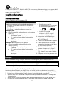
Contacting RISCO Group
RISCO Group is committed to customer service and product support.
You can contact us through our website www.riscogroup.com or as follows:
United Kingdom
Tel: +44-(0)-161-655-5500
E-mail: [email protected]
Belgium (Benelux)
Tel: +32-2522-7622
E-mail: [email protected]
Italy
Tel: +39-02-66590054
E-mail: [email protected]
China (Shanghai)
Tel: +86-21-52-39-0066
E-mail: [email protected]
Spain
Tel: +34-91-490-2133
E-mail: [email protected]
Israel
Tel: +972-3-963-7777
E-mail: [email protected]
France
Tel: +33-164-73-28-50
E-mail: [email protected]
Australia
Tel: +
1-800-991-542
E-mail: [email protected]
USA
Tel: +1-631-719-4400
E-mail: [email protected]
All rights reserved.
No part of this document may be reproduced in any form without prior written permission from the
publisher.
© RISCO Group 04/15 5IN2395 C
-
 1
1
-
 2
2
-
 3
3
-
 4
4
-
 5
5
-
 6
6
-
 7
7
-
 8
8
-
 9
9
-
 10
10
-
 11
11
-
 12
12
-
 13
13
-
 14
14
-
 15
15
-
 16
16


dans d''autres langues
- italiano: Risco WatchU Guida Rapida
- English: Risco WatchU Quick start guide
- español: Risco WatchU Guía de inicio rápido
Documents connexes
-
Risco WatchOUT Guide d'installation
-
Ris RWT312PR800A Manuel utilisateur
-
-
-
-
-
-
-
-
Risco Digi 412PT Manuel utilisateur
Autres documents
-
 Elkron TT19AM Guide d'installation
-
AVS Electronics JET DT Manuel utilisateur
-
 Elkron TT20AM Guide d'installation
-
 Elkron IMA20EX Guide d'installation
-
CAME PROXINET Guide d'installation
-
Ksenia ianitor User And Installer Manual
-
 Elkron KIT MP508TG/FC/IMA/L Guide d'installation
-
Bticino 4272 Mode d'emploi
-
CAME MR8003 Manuel utilisateur


