Intermatic ET90115CR Guide d'installation
- Taper
- Guide d'installation

www.intermatic.com
7777 Winn Road
Spring Grove, IL 60081
Manual No. 158--01050-REVA
ET90000 Series
Electronic Timer
Installation and Programming Guide
• Do not attempt to install or use your Intermatic product until you have read the safety instructions in this section. Save this
document and keep it in an easily accessible place.
• To avoid fire, shock, or death, turn off power at circuit breaker and test that power is off before wiring.
• Observe all national and local electrical and safety codes.
• Disconnect power when servicing or changing loads.
• Alterations or modifications to the device will create a hazard.
• Use copper conductors only. Use 10 AWG wire, minimum 105°C for 30 Amp loads.
• For outdoor locations, rainproof or wet location conduit hubs that comply with the requirements of UL 514B Conduit, Tubing,
and Cable Fittings for outdoor use, must be used.
Risk of Fire or Electric Shock
WARNING

ET90000 Series Electronic Timer
2
TABLE OF CONTENTS
Safety Information ....................................................2
Unpacking ................................................................2
Quick Start Guide .....................................................2
Product Description .................................................3
Installation ................................................................4
Mounting ..............................................................4
Wiring ...................................................................5
Door Assembly ....................................................8
Controls ....................................................................9
Programming ..........................................................10
Advanced Options ..................................................12
System Conguration Options ...............................14
Limited Three-Year Warranty ..................................16
Français ..................................................................17
Español ...................................................................33
SAFETY INFORMATION
IMPORTANT is a statement that informs about
installation, operation, maintenance, performance issues,
or general tips that are important but do not create a
hazard or safety concern.
EMISSIONS: This device complies with Part 15 of the
FCC Rules.
This Class A digital apparatus complies with Canadian
ICES-003.
IMPORTANT: Changes or modications not expressly
approved by the party responsible for compliance could
void the user’s authority to operate the equipment.
WARNING
WARNING indicates a hazardous situation which, if not
avoided, could result in death or serious injury.
CAUTION
CAUTION indicates a hazardous situation which, if not
avoided, could result in minor or moderate injury.
QUICK START GUIDE
1. MOUNT UNIT
Mount the unit to a stable surface, as required (see
Mounting, page 4).
2. CONNECT TO POWER
Connect unit to power (see Connect to Power, page 5).
3. INSTALL WIRING
Wire applications to device as required (see Install
Wiring, page 6).
4. PROGRAM BASIC INFORMATION
Input the current date and time. To begin using an
application, program an event. For complete information,
see Programming, page 10.
WARNING
To avoid fire, shock, or death, turn off power at circuit breaker
and test that power is off before wiring.
CAUTION
Some terminals in the ET90000-series electronic timer may be
energized even if the Status Screen is off. Check all terminals
and wires with an appropriate voltmeter before touching.
UNPACKING
Separate the timer from packaging materials and check
for any visual signs of damage. If you determine there
has been damage caused by shipping, le a claim
with the shipping company. If the device appears to
have been improperly assembled or does not operate
properly, return it for replacement or repair (see Limited
Three‑Year Warranty information at the end of this
manual).

ET90000 Series Electronic Timer
3
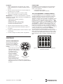
PRODUCT DESCRIPTION
The ET90000-series electronic timer from Intermatic
is a microprocessor based unit that allows you to turn
your application ON or OFF automatically for worry-free
operation. Automatically bring up and shut down lights,
turn on or turn off heating and cooling systems, activate/
deactivate alarms, or start and stop pumps. From the
compact keypad, easily program, schedule, and track
these “events” by a specic date (January 1, 2014) or by
a relative date (for example, the rst Monday of January
of any year), and by a specic time (11:00 p.m. CST)
or by astronomical time (example: sunrise). Separately
program holidays and downtimes, too.
Choose whether your event is going to be a xed ON
or OFF (single ON or OFF time for lights, for example)
or pulsed ON (ON time with specied duration, such as
ringing an alarm).
You can congure ET90000-series electronic timers to t
your needs. They are available in 1 and 2 circuit models,
or 4, 8, 12, 16 circuit models. The smaller units are
housed in either a Type 1 indoor enclosure or a Type 3R
“rainproof” outdoor enclosure. All 4, 8, 12, and 16 circuit
models are housed in the Type 3R enclosure.
FEATURES
• Automatic input voltage selection (no switches or
DIP settings)
• Date and time retention via 100-hour
supercapacitor
• USB port for input
• Program up to 4000 events, 99 holidays
• Sunrise/sunset tracking without Photocontrol
• Automatically adjusts for daylight saving time
• Upgrade rmware on-site via USB and Ethernet
• Ethernet connection for PC control and connecting
multiple timers
• External device support with CAN and serial ports
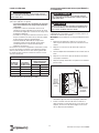
POWER RATINGS
Notes:
• N.C = normally closed, N.O. = normally open
• All VAC ratings are for 50/60 Hz
MAXIMUM LOADING EXAMPLES
Example:
(30 amps x 11 circuits) = 30 x 11 = 330 amps
Example:
(30 amps x 5 circuits) + (20 amps x 10 circuits) =
(150) + (200) = 350 amps
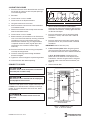
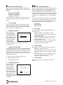
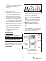
ESC
ENTER
ESC
ENTER
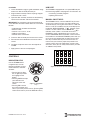
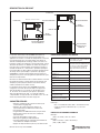
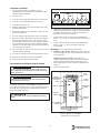
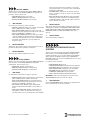
STATUS SCREEN
NAVIGATION KEYS
ESCAPE KEY
USB PORT
MANUAL
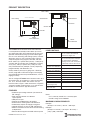
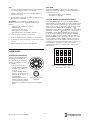
CIRCUIT ON/OFF KEYS
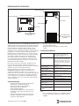
2-circuit control module
4 to 16-circuit control module
STATUS SCREEN
NAVIGATION KEYS
ESCAPE KEY
USB PORT
MANUAL
CIRCUIT ON/OFF KEYS
Input: 120-277 VAC, 50/60 Hz, 16 watts
max. for 1 and 2 circuit unit; 50
watts max. for larger unit
Output: 1 and 2 circuit panel, 60 amps
max.; 4-16 circuit panel, 350 amps
max. (both @25°C). Maximum
amperage for the 4-16 circuit panel
is reduced by 4.4A/°C above 25°C.
General Purpose and
Resistive @ 12-240 VAC:
20 amps (N.O.), 10 amps (N.C.)
General Purpose and
Resistive @ 12-240 VAC:
30 amps (N.O.)
Resistive @ 28 VDC: 20 amps (N.O.), 10 amps (N.C.)
Ballast @ 120-277 VAC: 20 amps (N.O.), 3 amps (N.C.)
Tungsten @ 12-120 VAC: 5 amps (N.O.)
Motor @ 120 VAC: 1 HP (N.O.), 1/4HP (N.C.)
Motor @ 240 VAC: 2 HP (N.O.), 1/2HP (N.C.)
Pilot duty 120-240 VAC: 470 VA (N.O.), 275VA (N.C.)
Maximum number of 30A
circuits (larger unit):
11
Maximum short circuit
rating both units:
5,000 amps

ET90000 Series Electronic Timer
4
TECHNICAL DATA
• Operating temperature: -40°F to 104°F (-40°C to
40°C)
• Dimensions 1 and 2 circuit unit (Type 1 encl.):
7-7/8H x 5 W x 3 inches D (20.0 H x 12.7 W x
7.6cmD)
• Dimensions 1 and 2 circuit unit (Type 3R encl.):
9-7/8 H x 5-5/8 W x 3-5/8 inches D (25.1 H x
14.3W x 9.2 cm D)
• Dimensions 4, 8, 12, 16 circuit unit: 19-1/8 H x
12-5/8 W x 5-3/8 inches D, including mounting
bracket; (48.6 H x 32.1 W x 13.7cm D)
• Knockout placement and sizes: for 1-2 circuit, 1/2-
3/4 inch combo on back, each side, and two on
bottom; for 4-16 circuit, 1/2-3/4 inch combo on each
side and six on bottom, 3/4-1 inch combo on each
side and four on bottom
• Weight: 1 and 2 circuit device, Type 1 encl.: 2.5lbs.
(1.13 kg); 1 and 2 circuit device, Type 3R encl.:
3.4lbs. (1.54 kg); 4-16 circuit unit: 18.6 lbs. (8.4 kg)
INSTALLATION
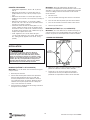
MOUNTING (1 AND 2 CIRCUIT ENCLOSURE)
IMPORTANT: Mounting screws and anchors not included.
1. Open the enclosure door.
2. Select the knockout you would like to use. Remove
the inner 1/2-inch knockout by inserting a athead
screwdriver in the slot; carefully punch the knockout
loose. Remove slug. If 3/4-inch knockout is required,
remove the outer ring with pliers after removing the
1/2-inch knockout. Smooth edge if necessary.
3. Place the enclosure in the desired mounting location
and mark mounting holes.
IMPORTANT: See Connecting to Power and Installing
Wiring below if you are going to bring power wires and
wires for connecting to applications through the back of
the enclosure. Connect these wires before mounting unit.
4. Drill holes.
5. Install anchors in wall, if needed.
6. Install the top screw rst and then hang the
enclosure.
7. Install the remaining screws through the enclosure
and into the wall.
8. Close enclosure door.
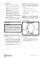
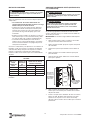
MOUNTING (4, 8, 12, 16 CIRCUIT ENCLOSURE)
IMPORTANT: Mounting screws and anchors not included.
Recommended screw size is #10; however, the type of
screw you select depends on the mounting surface.
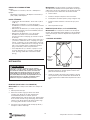
1. INSTALL BRACKETS
1. Remove the four hex head screws (5/16" slotted)
located on the top and bottom of the outside back of
the enclosure.
2. Using the screws that you just removed, install the
brackets with the keyhole portion extending past the
edge of the enclosure and providing an offset from
the back of the enclosure.
BRACKET
MOUNTING
SCREWS (4)
MOUNTING
BRACKETS (2)
CAUTION
For outdoor locations, rainproof, or wet location, you must use
conduit hubs that comply with the requirements of UL 514B
Conduit, Tubing, and Cable Fittings. For Outdoor Installation,
Fittings shall be identified with an enclosure type designation
(Type 3, 3X, 3S, 3SX, 3R, 3RX, 4, 4X, 6 or 6P) or as rain-tight
or liquid-tight on the carton. For indoor/outdoor locations,
provide sufficient space around the enclosure for convection
cooling.

ET90000 Series Electronic Timer
5
2. MOUNT ENCLOSURE
1. Place the enclosure in the desired location and mark
the location of at least two of the keyhole openings
in the mounting bracket.
2. Drill holes.
3. Install anchors in wall, if needed.
4. Install screws at the keyhole locations.
5. Hang the enclosure on the screws.
6. Mark the location of at least two of the round holes
in the bottom bracket.
7. Remove the enclosure from the top screws and drill
holes for the bottom screws.
8. Install anchors in wall, if needed.
9. Select knockouts you would like to use. Remove the
inner 1/2 or 3/4-inch knockout by inserting a athead
screwdriver in the slot and carefully punch the
knockout loose. Remove slug. If a larger knockout
is required, remove the outer ring with pliers after
removing the inner knockout. Smooth edge if
necessary.
10. Place the enclosure on the wall using the keyholes
in the top mounting bracket.
11. Install the remaining screws through the bottom
bracket and tighten.
12. Tighten the screws through the top mounting bracket.
13. Close enclosure door before operating.
CONNECT TO POWER
A 120 to 277 VAC power source supplies electricity to the
ET90000-series electronic timer, normally run through
conduit. To connect the power wires to the unit, follow
this procedure:
1. Secure conduit connectors to conduit before
connecting the hubs to the enclosure. After inserting
connectors into enclosure, carefully tighten hub lock
nut. Do not over-torque.
2. Insert the black power wire into the power board
(marked “L1” or “AC”) and secure with a athead
screwdriver.
3. Insert the white neutral wire into the power board
(marked “L2/N” or “IN”) and secure with a athead
screwdriver.
IMPORTANT: Color of wires may vary.
4. 1 and 2 circuit system: Attach the green ground
wire to the green hex head screw at the bottom of
the enclosure and secure with a athead screwdriver.
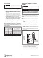
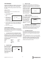
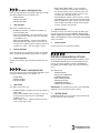
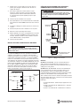
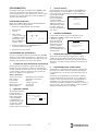
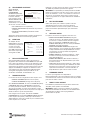
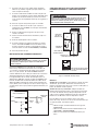
4, 8, 12, 16 circuit system: Connect the input
power wires to the terminals at the top left corner
of the device. Connect the ground wire to the green
hex head screw at the lower left of the device (see
Figure1).
5. Close enclosure door.
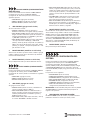
Figure 1: ET90000-Series Unit
(4, 8, 12, 16 circuit model)
WARNING
To avoid fire, shock, or death, turn off power at circuit breaker
and test that power is off before wiring.
WARNING
Make sure there is no wire insulation under the clamping plate
and firmly tighten the terminal screws.
CAUTION
Wire in accordance with national and local electrical and
safety codes.
NO-2NC-2NO-1NC-1
INAC
T
COM1 COM2
ET90215 2-CIRCUIT TERMINALS
TIMER
ELECTRICAL
POWER
TERMINALS
SCREEN
USB PORT
WIRING
TERMINALS
GROUNDING
CONNECTION
DOOR
SCREW
KEYPAD
ON/OFF
SWITCHES
WIRING
TERMINALS
CENTER KNOCKOUTS RESERVED FOR
LOW VOLTAGE WIRING
ESC
ENTER
Model_TEMP

ET90000 Series Electronic Timer
6
INSTALL WIRING
Observe these regulations before connecting any
applications to the device.
• The circuit conductors shall have an ampacity
not less than the maximum total load to be
controlled.
• Over current protection shall have an interrupting
rating sufficient for the application control circuit
voltage and the total load current of the equipment
being controlled.
• A fuse or circuit breaker shall be connected in
series with each ungrounded conductor (and shall
be able to open each conductor simultaneously).
• Maximum current rating for each circuit is 30 amps
Resistive and General Purpose. Refer to the Power
Ratings section on page 3 for other ratings.
Wire components and applications to the terminal boards
as needed. Terminal boards are located underneath
the faceplate on the small unit, and on the right and left
sides of the large unit. Insert wires into slots; secure with
athead screwdriver.
WIRING INFORMATION – COPPER CONDUCTORS ONLY
WIRE SIZE
105°C MIN
INSULATION
SUPPLY
CIRCUIT
BREAKER
RATING
MAX MOTOR LOAD
(CONTINUOUS DUTY)
120V 240V
AWG AMP HP HP
14 15 1/2 1
12 20 1 2
10 30 – –
Terminal block wire gauge range 20 to 6 AWG
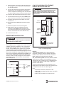
ADDING RELAY BOARDS (4, 8, 12 CIRCUIT
SYSTEMS)
You can add additional four-circuit relay boards to the 4,
8 and 12 circuit model to a maximum of 16 circuits per
system.
IMPORTANT: Do not exceed 350 amps maximum panel
load.
1. Open outer door and remove and retain the two
screws that secure the interior deadfront to the
chassis.
2. Remove and retain the screw that secures the
controller door assembly.
3. Select the position to install the new relay board.
4. Remove and retain the outer two screws that secure
the ller panel.
5. Remove the ller panel by bending at the serration
until it breaks.
NC NO COM
NC NO COM
NC NO COM NC NO COM
ET90000 SERIES 4-CIRCUIT RELAY BOARD
CIRCUITS
1-4, 5-8, 9-12
OR 13-16,
DEPENDING
ON SLOT
USED
INDEXED PLUG FOR
CONNECTION TO
INTERFACE BOARD
6. Open the door assembly and remove and retain the
two screws just opposite of the ller panel screws.
7. Insert the new relay board assembly into the
opening, cable rst. The board should sit on top of
the brackets with its mounting holes positioned over
the holes of the previously-removed screws.
WARNING
To avoid fire, shock, or death, turn off power at circuit breaker
and test that power is off before wiring.
WARNING
To avoid fire, shock, or death, turn off power at circuit breaker
and test that power is off before wiring.
CAUTION
Some terminals in the ET90000-series electronic timer may be
energized even if the Status Screen is off. Check all terminals
and wires with an appropriate voltmeter before touching.

ET90000 Series Electronic Timer
7
8. Make sure there are no wires under the board. Use
the (4) original screws to secure the relay board to
the mounting bracket.
9. Connect the cable from relay board to the Interface
board. Use the next available open connector (to
maintain sequential numbering). Push the connector
into the mating connector until the connector latches.
10. Close the door assembly and secure with its screw.
11. Connect/wire the circuit(s) that the ET90000-series
timer will control to the relay board terminal blocks.
12. Check the wiring to ensure that there are no mis-
wired circuits.
13. Reinstall the interior deadfront and secure with its
screws.
14. Remove the plastic cover over the keypads.
15. Apply power to the unit and program the new
channels. The ET90000 system recognizes the
new relay board, displays the circuits on the Status
Screen, and activates the correct ON/OFF keys.
16. Close enclosure door.
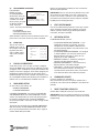
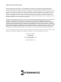
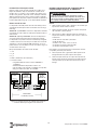
REMOTE SWITCH INSTALLATION
The ET90000 system is equipped with remote switching
capability. There are 2 overrides for the 1 and 2 circuit
models and 8 overrides for the 4, 8, 12, and 16 circuit
models. The ET90000 system supplies ve-volt limited
current through terminal connections located on the
system interface board. The maximum length of a remote
switch circuit is 1000 feet using 20 AWG twisted pair wire.
The factory recommends 16 AWG through 26 AWG wire
sizes and low voltage SPST (single-pole, single-throw)
switches. Route the cable through one of the knockouts
at the bottom center of the enclosure (see illustration
below and Figure 2).
MANUAL
SWITCH
5V
REMOTE (1 - 8)
ET90000 SERIES
EXAMPLE REMOTE INPUT
GND
5VDC
100 OHM
INPUT
100K
10K
GROUND
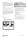
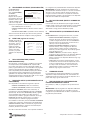
LOW-VOLTAGE WIRING FOR ETHERNET,
REMOTE SWITCH AND CAN BUS
Figure 2: Low Voltage Wiring
Ethernet
1 and 2 circuit system: For the optional Ethernet
connection, attach the Ethernet module to the plastic
deadfront at the bottom of the enclosure; connect the
ribbon cable to the wiring port on the left side.
4, 8, 12, 16 circuit system: Locate the Ethernet module
underneath the deadfront and hinged door in the low-
voltage wiring area. The device uses standard Ethernet
connector cable. Ethernet cable range is 100 meters
between active devices.
Route the cable through one of the knockouts at the
bottom center of the enclosure. Push the connector onto
the module until the latch sets. See Figure 2.
Note:
• Power LED: illuminates while power is ON
• LED1 on RJ-45 model: Ethernet speed – 10 (OFF)
or 100 (ON)
• LED2 on RJ-45 model: link and data activity
WARNING
To avoid fire, shock, or death, turn off power at circuit breaker
and test that power is off before wiring.
CAUTION
Keep low-voltage wiring separate from high-voltage wiring,
including deadfront material between wiring areas. Use
separate conduit for low-voltage wiring with no line voltage
circuits included.
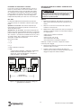
CAN BUS AND REMOTE
INPUT CONNECTORS
4, 8, 12, AND 16 CIRCUIT MODELS
(DEADFRONT REMOVED)
ESC
ENTER
CAN BUS
CONNECTORS
ETHERNET
CONNECTION
REMOTE INPUT
CONNECTORS
1 AND 2 CIRCUIT MODELS

ET90000 Series Electronic Timer
8
Remote Switch Installation
The serial port consists of multiple 2-wire inputs on
the terminal block. There are two 2-wire inputs on the
1 and 2 circuit models and eight 2-wire inputs on the
larger models. You can use a standard SPST wall switch
to make this connection. Install wiring for serial port
applications by inserting wiring into the available slot,
then securing with a athead screwdriver.
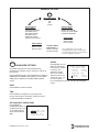
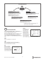
CAN Bus
CAN (controller area network) devices provide advanced
remote switch capabilities over a longer range.
1 and 2 circuit system: Connect devices through a four-
wire interface on the terminal block above the deadfront.
4, 8, 12, 16 circuit system: Connect devices on the rear
of the interface PCB. Devices can be wired daisy-chain or
star. When the line is required to be “terminated,” connect
the TRM terminal to the C_H terminal with an external
jumper. Route the cable through one of the knockouts at
the bottom center of the enclosure.
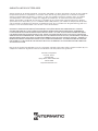
CAN Bus Terminal Block
1 +5V
2 C_H
3 C_L
4 TRM (120 ohm termination)
5 GND
• Maximum bus length: 1,000 Meters (3280 Feet)
• Maximum number of remote devices: 16
• Wire type: 1 pair twisted with shield – UL Type CL2
• Wire gauge range: 16 to 26 AWG
C_HC_L TRM
77((5500,,11$$//%%//22&&..33
GND
C_HC_L TRM GND C_ HC_L TRM GNDC_HC_L TRM GND
MAX LENGTH = 1000 METERS
(3280 FEET)
ET9XX15
CONTROLLER
CAN BUS
DEVICE #1
CAN BUS
DEVICE #2
SHIELDSHIELDSHIELD
1 PAIR TWISTED WITH SHIELD
UL TYPE CL2
Figure 3: Example showing daisy-chain connections’
end units with termination
DOOR ASSEMBLY REMOVAL AND
INSTALLATION – 4 TO 16 CIRCUIT MODELS
Removal
1. Open outer door; remove and retain the two screws
that secure the interior deadfront to the chassis.
2. Remove and retain the screw that secures the
controller door assembly and open the door.
3. Disconnect the following cables from the controller
and interface boards and label each connector/wire
with its location.
• Cable between controller and interface
• Ethernet cable
• Channel 1-4, 5-8, 9-12, 13-16
• CAN bus connections
• Remote switch connections
Note: Some connectors have a latching feature; press to
remove.
4. Close the door; remove and retain the top hinge
screw located at the top of the assembly.
5. Lift up the assembly until it clears the hinge support,
then lift the assembly towards the top of the
enclosure until it is free of the bottom hinge support.
CAUTION
Power to the ET90000 System must be OFF before adding or
removing any system components. Failure to remove power
could result in personal injury, damage to the equipment, and
voiding of the product warranty.

ET90000 Series Electronic Timer
9
Installation
1. Locate the bottom hinge pin; guide the bottom hinge
hole on the door assembly onto the pin.
2. Align the door assembly with the top hinge support
and secure with a screw.
3. Open the door assembly and connect the following
cables to the controller and interface boards:
IMPORTANT: The connectors are polarized and only t
in one direction. DO NOT FORCE them into a connector
location.
• Cable between controller and interface
• Ethernet cable
• Channel 1-4, 5-8, 9-12, 13-16
• CAN bus connections
• Remote switch connections
4. Close the door assembly and secure with its screw.
5. Reinstall the interior deadfront and secure with its
screws.
6. Congure the plastic covers over the keypads as
needed.
7. Apply power to the unit and reprogram.
CONTROLS
NAVIGATION KEYS
Use the ET90000 timer’s
navigation keys to scroll
through the display screens,
make selections, and enter
variables.
• Pressing the up, down,
left, or right keys moves
the highlight on the
display.
• Pressing ENTER accepts
your selection and
advances to the next
screen.
• Pressing ESC cancels
the screen selection and
returns you to the previous screen. (Pressing ESC
several times returns you to the STATUS screen.)
USB PORT
The ET90000 is equipped with a hi-speed USB 2.0 port
for transferring updates and programs. Port functions are:
• transferring schedule programs
• updating the rmware
MANUAL ON/OFF KEYS
The ET90000 unit has a manual ON/OFF key for each
circuit in the system. Each key manually overrides the
associated circuit, turning the circuit OFF if it is ON and
ON if it is OFF. The condition of each circuit displays on
the default STATUS SCREEN.
01
E
indicates circuit
number 1 is OFF and the circuit is ENABLED;
01
E
indicates circuit number 1 is ON and the circuit is
ENABLED. If the E is blocked out on the screen, the
circuit is DISABLED. Manual overrides can be used but
the schedule is not followed. ET90000 systems with 4, 8
or 12 circuits are shipped with all sixteen manual ON/
OFF keys installed. The keys for unused circuits are
inactive until you install the proper relay board in the
system. Inactive keys are shipped with a plastic cover
over them, which you can easily remove when you add
an additional relay board.
1
ON/OFF
2
ON/OFF
3
ON/OFF
4
ON/OFF
5
ON/OFF
6
ON/OFF
7
ON/OFF
8
ON/OFF
9
ON/OFF
10
ON/OFF
11
ON/OFF
12
ON/OFF
13
ON/OFF
14
ON/OFF
15
ON/OFF
16
ON/OFF
Figure 5: 16-Circuit System ON/OFF Keys
ESC
ENTER
Figure 4: Navigation
Keys

ET90000 Series Electronic Timer
10
PROGRAMMING
Program the ET90000-series electronic timer using the
navigation keys (see Figure 4). Some of the inputs you
program are simple choices: yes/no, enable/disable,
etc.; others involve inputting variables in alpha-numeric
characters.
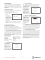
INITIAL SETUP
From the STATUS screen, press ENTER. Use the
navigation keys to:
1. Choose INITIAL SETUP.
2. Input the current
date.
3. Input the correct
time (choose 12-
HOUR, example:
2:20 PM; or 24-
HOUR, example:
14 hours, 20 minutes).
4. Choose whether you would like the ET90000-series
timer to update the time automatically for daylight
saving time.
5. Select your time zone.
PROGRAMMING EVENTS
After you have set up the ET90000-series timer initially,
you can program an “event.” An event is something you
would like the device to control, such as turning ON lights
or turning OFF an alarm.
1. CHOOSE SPECIFIC OR RELATIVE DATE
To program an event, rst choose whether you would like
your event to occur on a specic or relative date. Program
a specic date by choosing the month and day; program
a relative date by choosing a date such as the 2nd week
of January, or the 10th day of each month.
Available Options:
1st-31st Mon-Sun Jan-Dec
Each Week Year
Last Weekday Month
First Weekend
Day
2. SPECIFY TIME
Choose a time when
you want your event
to occur. Or choose
astronomic time, which
is sunrise or sunset,
plus or minus a variable
number of minutes
(up to ±120), per your
requirements.
3. CIRCUIT TYPE
For your event, choose whether you would like the
ET90000-series electronic timer to turn your application
ON or OFF, then choose whether the circuit will have a
xed ON or a pulse ON.
Fixed means a steady
current. Pulse means a
steady current which is
ON for a specied time
(input hours, minutes,
and seconds of pulse)
and then turns OFF.
4. NAME YOUR EVENT
You can choose to give your event a name, such
as SLIGHTS or PUMP 1. Enter the name (up to 10
characters) using the
alpha-numeric display.
The ET90000 system
chooses a name for
you if you do not name
your event, for example
Event 1.
5. DETERMINE CIRCUIT CONTROL
After naming your event, select which circuit(s) the event
controls. Select as few as one circuit, or as many as 16
circuits on the large capacity device. (Note: Up to 32
external circuits will be available in the future.)
6. PROGRAM HOLIDAYS
If your event runs during times where there are one or
more holidays, which may supplant normal event times
and dates, you must program this information into the
device.
Similar to programming an event, you name the holiday,
set up date and time (in this case, choose the beginning
and end of the holiday), then program events into the
holiday. Also similar to programming primary event(s),
select your circuits and what they do: turn ON with a
xed or pulse duration or turn OFF.
STATUS
01
7/14/11 2:20 PM
E
02
E
TIMESWITCH
EVENT 1
TIME TYPE: ASTRO
SUNRISE
ADJUSTMENT +33 MINS
EVENT 1
TYPE: PULSE
00:01:00
HH:MM:SS
NAME: EVENT 1
ABCDEFGHIJKLM
NOPQUSTUVWYXZ
012345678 /-:
DEL ACCEPT

ET90000 Series Electronic Timer
11
7. SELECT ASTRO(NOMIC) ZONES
If you have previously programmed an event or a
holiday based on astronomic time, you must select an
astronomic zone after you have programmed in all of
your variables, events, and holidays. Select from the
following regions:
• USA STATES
• MEXICO
• CANADA
• USA
TERRITORIES
Then select the
appropriate COUNTRY
LOCATION and LOCATION QUADRANT.
8. REVIEW YOUR EVENT
After you nish programming your events, you can
choose YES to review it. Review the program by circuit,
by event (ALL, HOLIDAY, or RELATIVE) and by specic
date. If the event requires changes, press ENTER with
the event highlighted to proceed directly to Advanced
Options. You can also edit or change your event from
ADVANCED OPTIONS on the SETUP screen.
SELECT ASTRO ZONE
COUNTRY
UNITED STATES
COUNTRY LOCATION
ILLINOIS
LOCATION QUADRANT
CENTER
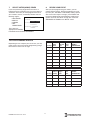
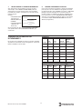
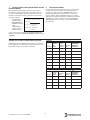
TIPS ON PLANNING EVENTS
Depending on how complex your circuits are, you may
prefer to plan your events before programming using a
table similar to the one at the right.
EVENTS
Circuit(s)
Event
Name
Effective
Days
Start
Time
Type:
ON/OFF
FIXED/PULSE
HOLIDAYS
Circuit(s)
Name of
Holiday
Begin
Date
End
Date
Type:
ON/OFF
FIXED/PULSE

ET90000 Series Electronic Timer
12
ENTER
ADVANCED OPTIONS
Use Advanced Options to edit already-existing
programming, congure circuits and zones, and set up
your system.
From the STATUS screen, press ENTER and navigate to
ADVANCED OPTIONS. Press ENTER to access DATE,
TIME, DST, or ASTRO on the DATE/TIME CONFIG
screen.
DATE
Press ENTER to correct the date.
TIME
Press ENTER to change the current time (hours,
minutes, AMor PM) or the display mode for the time
(12HOUR AM/PM or 24 HOUR).
DST (DAYLIGHT SAVING TIME)
Press ENTER to
enable/disable DST, set
the DST time zone, and
set up effective dates
(start and end date of
DST).
ASTRO
From ASTRO, you can
dene an Astronomic
zone (country, location
in country, and
quadrant location).
Also, if you need to
adjust the time of the
astronomic zone, you
can do so against
the “calculated time” from the ASTRO ADJUSTMENT
screen.
DT.DST.EFF—DATES
START DATE (SUN):
FOURTH WK OF FEB
END DATE (SUN):
FIRST WK OF OCT
DT.ASTRO .ADJUSTMENT
CALCULATED TIME
SUNRISE SUNSET
5:26 AM 5:29 PM
ENTER NEW TIME
SUNRISE SUNSET
5:26 AM 5:29 PM
CIRCUIT CONFIG
EDIT CKT NAME
ENABLE CKT EVENTS
MANUAL ACTIVATE MODE
EXTERNAL OVERRIDE
ZONE CONFIG
ADD ZONE
MODIFY ZONE
DELETE ZONE
HOLIDAY CONFIG
ADD HOLIDAY
MODIFY HOLIDAY
DELETE HOLIDAY
EVENT CONFIG
ADD EVENT
MODIFY EVENT
DELETE EVENT
SYSTEM CONFIG
REVIEW MODE
PROG COPY/RESTORE
PASSWORD SETUP
EDIT SYSTEM NAME
NETWORK SETUP
FIRMWARE UPDAT E
RESET TO FAC DEFAULT
ENTER
DATE/TIME CONFIG
DATE
TIME
DST
ASTRO
The conguration screens can be
navigated using the right or left keys. The
accompanying instructions are presented
based on a right-key sequence.
ADVANCED OPTIONS

ET90000 Series Electronic Timer
13
CIRCUIT CONFIG(URATION)
When you press the right key from TIME, DATE, DST, or
ASTRO, you have the following options under CIRCUIT
CONFIG:
• EDIT CKT (circuit) NAME
• ENABLE CKT EVENTS
• MANUAL ACTIVATE MODE
• EXTERNAL OVERRIDE
Each relay or output is dened as a circuit. Each circuit
can be independently congured using the following
options.
1. EDIT CKT NAME
Enter or change the name of the circuit(s). First select
the circuit you wish to change, then use the keypad to
enter or change the name (up to 10 characters; default
name is CIRCUIT 1, CIRCUIT 2, etc.).
2. ENABLE CKT EVENTS
When you enable a
circuit, it adheres to
the scheduled events.
However, events do not
turn a disabled circuit
ON or OFF but you can
still control disabled
circuits manually
via pushbuttons or
overrides. Add or remove the checkmark to enable/
disable the circuit.
3. MANUAL ACTIVATE MODE
This determines how the relays are controlled. If FIXED,
a pushbutton toggles the circuit ON and OFF normally. If
PULSE, after you turn the circuit on manually, the circuit
automatically turns OFF when the pulse duration expires.
(Note: You can always control circuits manually via the
pushbuttons.) To activate:
A. Select the circuit you would like to control.
B. Choose FIXED or PULSE.
C. If PULSE, input duration.
4. EXTERNAL OVERRIDE
You can use external
remote override
switches to control
circuits. 1 and 2
circuit models have
two overrides; 4 to 16
circuit units have up to
eight overrides. Select
which circuits you will
override, which zones,
and whether the override will be xed or pulse. If pulse,
set duration.
ZONE CONFIG(URATION)
You will use these options to establish and dene zones.
You can set up a zone and use it to control one or more
circuits, including the circuit’s associated events and
holidays. For example, you may create Zone A, which is
comprised of circuits 1, 3 and 6 that have four events and
three holidays, including each event’s and each holiday’s
variables such as the dates, times, etc., associated with
them.
If events control zones instead of circuits, you can modify
the circuits in a zone without changing any events. To
congure, press the right key from CIRCUIT CONFIG to
land on ZONE CONFIG where your options are:
• ADD ZONE
• MODIFY ZONE
• DELETE ZONE
1. ADD ZONE
To add a zone, press ENTER from ADD ZONE where
your choices are:
• ENABLE A ZONE – You establish a zone by
enabling it. Disabling a zone causes it to ignore the
programmed schedule.
• EDIT ZONE NAME – Here you can give the zone
a name (up to 10 characters; default names are
ZONE 1, ZONE 2, etc.).
• EDIT ZONE CIRCUIT LIST – Choose the circuit(s)
you wish to include in the zone by placing a
checkmark next to the circuit(s).
2. MODIFY ZONE
Select the zone you would like to modify, then choose:
• ENABLE – Choose YES or NO.
• EDIT ZONE NAME – Edit the zone’s name (up to
10 characters; default names are ZONE 1, ZONE
2, etc.).
• EDIT ZONE CIRCUIT LIST– Choose the circuit(s)
you wish to include in the zone by placing a
checkmark next to the circuit(s).
3. DELETE ZONE
Select the zone you would like to delete, then press
ENTER.
CIRCUIT . ENABLE
ENABLE/DISABLE CKTS
NONE
1: CIRCUIT 1
2: CIRCUIT 2
DONE
CIRCUIT . OVERRIDE
OVERRIDE 1
SELECT OVERRIDE
ACTIVATE MODE
FIXED
PULSE HH: MM: SS
00: 01: 00

ET90000 Series Electronic Timer
14
HOLIDAY CONFIG(URATION)
Press the right key again from ZONE CONFIG to land on
HOLIDAY CONFIG where your options are:
• ADD HOLIDAY
• MODIFY HOLIDAY
• DELETE HOLIDAY
1. ADD HOLIDAY
You create a holiday when you:
• ENABLE A HOLIDAY – Establish the holiday by
choosing YES or NO.
• EDIT HOLIDAY NAME – Give the holiday a name
(up to 10 characters; default names are HOLIDAY
1, HOLIDAY 2, etc.).
• EDIT HOLIDAY DATES – Choose from FIXED or
RELATIVE holiday, where xed is exact rst and
last days of the holiday (month and day); relative for
example, is 1st day = July 4th, length = 3 days.
2. MODIFY HOLIDAY
Select the holiday you would like to enable, change/add
name, and/or edit the holiday’s dates (same as above).
3. DELETE HOLIDAY
Choose any holiday(s) you would like to delete from the
zone.
EVENT CONFIG(URATION)
Press the right key again from HOLIDAY CONFIG to land
on EVENT CONFIG where your options are:
• ADD EVENT
• MODIFY EVENT
• DELETE EVENT
1. ADD EVENT
You add an event when you:
• ENABLE EVENT – Establish an event by choosing
YES or NO.
• EDIT EVENT NAME – Give the event a name (up
to 10 characters; default names are EVENT 1,
EVENT 2, etc.).
• EDIT EVENT TYPE – Choose whether this event
turns a circuit ON or OFF.
• EDIT EVENT DATE/TIME – Input a xed date
(month and day) or a relative date (example, 1st
day of each month); input a xed time (hour and
minute) or an astro time (sunrise or sunset, up to
±120 minutes allowable adjustment).
• CKT/ZONE/HOL LISTS – Select circuit(s), zone(s)
and holiday(s) for this event by placing checkmarks.
• EDIT ACTIVATION TYPE – Select activation mode,
either FIXED or PULSE. If PULSE, enter duration
in hours, minutes, and seconds.
2. MODIFY EVENT
To modify an event, rst select the event to modify then
change or edit the event under ENABLE EVENT, EDIT
EVENT NAME, EDIT EVENT TYPE, EDIT EVENT DATE/
TIME, CKT/ZONE/HOL LISTS, and/or EDIT ACTIVATION
TYPE (see above).
3. DELETE EVENT
Choose the event you would like to delete.
SYSTEM CONFIGURATION OPTIONS
Press the right key again from EVENT CONFIG to land
on SYSTEM CONFIG. Note: From the STATUS screen,
you can also press ENTER; navigate to ADVANCED
OPTIONS, press ENTER again, then press the left key
once.
Your options are:
• REVIEW MODE
• PROG COPY/RESTORE
• PASSWORD SETUP
• EDIT SYSTEM NAME
• NETWORK SETUP
• FIRMWARE UPDATE
• RESET TO FAC DEFAULT
IMPORTANT: Use the ESC key to return to the SYSTEM
CONFIG screen after entering these options.
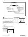
1. REVIEW MODE
In REVIEW MODE, you can examine the parameters for
all your events by circuit and date.

ET90000 Series Electronic Timer
15
A) PROGRAMMED SCHEDULE
From REVIEW
MODE, you land
on PROGRAMMED
SCHEDULE. After you
choose which circuit’s
schedule you would
like to review, you land
on SELECT EVENT
TYPE. From this
screen, select from the following:
• ALL EVENTS
• HOLIDAY EVENTS ONLY
• RELATIVE EVENTS ONLY
Select the date of the event you would like to review and
press enter. The screen shows any event scheduled.
B) EVENT LOG
You can also view an
EVENT LOG, such as
this example. The event
log stores the most
recent 1,000+ events
and can be saved to
USB.
2. PROG COPY/RESTORE
Under this function, you can copy or restore a program
into the ET90000-series timer from the USB port. To copy
a program, insert a USB drive into the port and follow the
prompts. To restore a program, select which program you
would like to restore from the list on the screen; press
ENTER to delete the current schedule and replace it with
the saved USB schedule. Note: Backup your schedule to
USB in case it is unintentionally modied, reset, etc.
3. PASSWORD SETUP
On this screen, your choices are:
• ENABLE PASSWORD
• CHANGE PASSWORD
In ENABLE PASSWORD, your choices are ENABLED
and DISABLED. When you select ENABLED, it means
screens are viewable but you must enter the password
to change or add information. Choosing DISABLED
means no password is necessary to view, change or add
information.
To change the password, press CHANGE PASSWORD.
After you land on the SYS PSWORD CHANGE screen,
key in up to 10 alphanumeric characters; key in again to
conrm. Write down password!
Note: If the password is enabled, you can still reset the
device to factory defaults.
IMPORTANT: You can reset to factory defaults even if you
do not know the password; in fact, this is the only way
to start “from scratch,” and enter a new password, if the
password is permanently lost. Always copy the schedule
to USB prior to resetting the timer.
4. EDIT SYSTEM NAME
Use this for identication purposes to name your system
when networking multiple timers together. Change or
edit the system’s name using up to 10 alpha/numeric
characters, then press ACCEPT.
5. NETWORK SETUP
In NETWORK SETUP, you can:
• CONFIGURE NETWORK ADDRESS – If you
would like to connect to a network, you must
congure the network address. ENTER the IP
(internet protocol) address, the subnet mask, and
the default gateway.
• CONFIGURE REMOTE ADDRESS – To congure
a remote address, you must rst connect to an
Ethernet device (see page 7). Then you can
program up to 16 IP addresses.
• REMOTE CONNECT – Follow the prompts to
connect to another Ethernet device.
• REMOTE DISCONNECT – First connect to an
Ethernet device, then follow prompts.
• TIME SYNC – Sends the time information from
the current timer to all timers, so clocks are
synchronized. To synchronize timers, rst connect
to an Ethernet device, then follow the prompts.
6. FIRMWARE UPDATE
Firmware updates are available at
http://www.intermatic.com. To install an update from a
ash drive, insert drive into the USB port, then follow the
prompts.
7. RESET FACTORY DEFAULTS
Choose NO or YES. Be certain you want to do this!
IMPORTANT: Copy the schedule to USB prior to resetting
the timer. If you reset factory defaults, you lose all custom
programming.
SYS. REVIEW-MODE
CIRCUIT 1
SELECT EVENT TYPE
ALL EVENTS
HOLIDAY EVENTS ONLY
RELATIVE EVENTS ONLY
EVENT LOG
PARKING L1
ON
-MANUAL-
OFF
-SERIAL-
ON
12/31/12
5:00 PM
12/31/12
2:00 PM
12/31/12
10:00 AM

LIMITED THREE-YEAR WARRANTY
If within the warranty period specied, this product fails due to a defect in material or workmanship, Intermatic
Incorporated will repair or replace it, at its sole option, free of charge. This warranty is extended to the original
purchaser only and is not transferable. This warranty does not apply to: (a) damage to units caused by accident,
dropping or abuse in handling, acts of God or any negligent use; (b) units which have been subject to unauthorized
repair, opened, taken apart or otherwise modied; (c) units not used in accordance with instructions; (d) damages
exceeding the cost of the product; (e) sealed lamps and/or lamp bulbs, LEDs and batteries; (f) the nish on any
portion of the product, such as surface and/or weathering, as this is considered normal wear and tear; (g) transit
damage, initial installation costs, removal costs, or reinstallation costs.
INTERMATIC INCORPORATED WILL NOT BE LIABLE FOR INCIDENTAL OR CONSEQUENTIAL DAMAGES.
SOME STATES DO NOT ALLOW THE EXCLUSION OR LIMITATION OF INCIDENTAL OR CONSEQUENTIAL
DAMAGES, SO THE ABOVE LIMITATION OR EXCLUSION MAY NOT APPLY TO YOU. THIS WARRANTY IS IN
LIEU OF ALL OTHER EXPRESS OR IMPLIED WARRANTIES. ALL IMPLIED WARRANTIES, INCLUDING THE
WARRANTY OF MERCHANTABILITY AND THE WARRANTY OF FITNESS FOR A PARTICULAR PURPOSE, ARE
HEREBY MODIFIED TO EXIST ONLY AS CONTAINED IN THIS LIMITED WARRANTY, AND SHALL BE OF THE
SAME DURATION AS THE WARRANTY PERIOD STATED ABOVE. SOME STATES DO NOT ALLOW LIMITATIONS
ON THE DURATION OF AN IMPLIED WARRANTY, SO THE ABOVE LIMITATION MAY NOT APPLY TO YOU.
This warranty service is available by either (a) returning the product to the dealer from whom the unit was purchased,
or (b) completing a warranty claim on line at www.intermatic.com. This warranty is made by:
Intermatic, Incorporated
Customer Service
7777 Winn Rd.
Spring Grove, Illinois 60081-9698
815-675-7000
http://www.intermatic.com

www.intermatic.com
7777 Winn Road,
Spring Grove, IL 60081
Manuel n° 158--01050-REVA
Minuterie électronique
Série ET90000
Guide d’installation et de
programmation
• Ne pas tenter d’installer ni d’utiliser ce produit Intermatic avant d’avoir lu les instructions de sécurité de cette section. Conserver ce
document à un endroit aisément accessible.
• Pour écarter les risques d’incendie, de choc électrique ou de mort, couper l’alimentation au niveau du disjoncteur et vérifier l’absence
de courant avant de câbler.
• Respecter tous les codes de l’électricité et de sécurité en vigueur.
• Débrancher l’alimentation électrique pour tout entretien ou changement de charge.
• Les altérations ou modifications de cet appareil sont sources de danger.
• Utiliser exclusivement des conducteurs en cuivre. Utiliser du fil n°10 AWG, de 105°C minimum, pour charges de 30A.
• Pour les installations extérieures, utiliser des embouts de raccordement de conduit imperméable ou pour zone humide conformes aux
exigences d’UL 514B Conduit, Tubing, and Cable Fittings.
Risque d’incendie ou de choc électrique
AVERTISSEMENT

Minuterie électronique Série ET90000
18
TABLE DES MATIÈRES
Informations sur la sécurité ..............................................18
Déballage .........................................................................18
Guide de démarrage .........................................................18
Description du produit .......................................................19
Installation ....................................................................... 20
Montage...................................................................... 20
Câblage ...................................................................... 21
Porte ........................................................................... 24
Commandes .................................................................... 25
Programmation ................................................................ 26
Options avancées ............................................................ 28
Options de conguration du système .............................. 30
Garantie limitée trois ans ................................................. 32
INFORMATIONS SUR LA SÉCURITÉ
IMPORTANT est une déclaration portant sur des questions
d’installation, d’exploitation, d’entretien ou de fonctionnement
ou un conseil général qui ont de l’importance mais ne
présentent pas de danger ni d’atteinte à la sécurité.
ÉMISSIONS: Ce dispositif est conforme à la Partie 15 des
Règles FCC.
Cet appareil numérique de la classe A est conforme à la norme
NMB-003 du Canada.
IMPORTANT : Les changements ou modications non
expressément approuvés par la partie responsable de la
conformité peut invalider l’autorité de l’utilisateur à exploiter ce
matériel.
AVERTISSEMENT
AVERTISSEMENT indique une situation dangereuse susceptible, si elle
n’est pas évitée, d’entraîner la mort ou des blessures graves.
ATTENTION
ATTENTION indique une situation dangereuse susceptible, si elle n’est
pas évitée, d’entraîner des blessures mineures à modérées.
GUIDE DE DÉMARRAGE
1. MONTER L’APPAREIL
Monter l’appareil sur une surface stable, selon les besoins (voir
Montage, page 20).
2. RACCORDER À L’ALIMENTATION ÉLECTRIQUE
Raccorder l’appareil à l’alimentation électrique (voir Raccorder
à l’alimentation électrique, page 21).
3. POSER LE CÂBLAGE
Câbler les applications à l’appareil comme il se doit (voir Poser
le câblage, page 22).
4. PROGRAMMER LES DONNÉES DE BASE
Entrer la date et l’heure courantes. Pour commencer à
utiliser une application, programmer un événement. Voir les
informations complètes sous Programmation, page 26.
AVERTISSEMENT
Pour écarter les risques d’incendie, de choc électrique ou de mort,
couper l’alimentation au niveau du disjoncteur et vérifier l’absence de
courant avant de câbler.
ATTENTION
Certaines bornes de la minuterie électronique série ET90000 peuvent
être sous tension même si l’écran d’état est éteint. Contrôler tous les
fils et les bornes au voltmètre avant de les toucher.
DÉBALLAGE
Séparer la minuterie des matériaux d’emballage et vérier
visuellement l’absence de dommages. En cas de dommages
causés par le transport, déposer une réclamation auprès du
transporteur. Si l’appareil semble avoir été assemblé de façon
incorrecte ou s’il ne fonctionne pas correctement, le renvoyer
pour être remplacé ou réparé (voir Garantie limité trois ans à la
n de ce manuel).

Minuterie électronique Série ET90000
19
DESCRIPTION DU PRODUIT
La minuterie électronique série ET90000 d’Intermatic est
un appareil à microprocesseur qui permet de mettre une
application en marche ou à l’arrêt automatiquement et d’assurer
un fonctionnement sans souci. Elle s’utilise pour allumer et
éteindre automatiquement l’éclairage, mettre en marche ou à
l’arrêt des systèmes de chauffage et de refroidissement, activer/
désactiver des alarmes ou démarrer et arrêter des pompes. Le
pavé de touches compact permet de programmer, planier et
surveiller aisément ces «événements» par dates spéciques
(1er janvier 2014) ou dates relatives (le premier lundi de janvier
de chaque année, par exemple) et par heures spéciques
(23h00 HNC) ou heures astronomiques (lever du soleil, par
exemple). Vous pouvez aussi programmer séparément les jours
fériés et les temps d’arrêt.
Choisissez si l’événement doit être un état de marche ou d’arrêt
xe (temps de marche ou d’arrêt unique pour l’éclairage, par
exemple) ou pulsé (temps de marche d’une durée donnée,
comme l’activation d’une alarme sonore).
Les minuteries électroniques série ET90000 peuvent être
congurées en fonction des besoins. Elles sont proposées
dans des modèles à 1 et 2 circuits ou des modèles à 4, 8,
12, 16 circuits. Les modèles les plus petits se présentent
dans un boîtier intérieur de type 1 ou un boîtier extérieur
«imperméable» de type 3R. Tous les modèles à 4, 8, 12 et 16
circuits se présentent dans un boîtier de type 3R.
CARACTÉRISTIQUES
• Sélection automatique de la tension d’entrée (sans
commutateur ni réglage DIP)
• Rétention de la date et de l’heure grâce à un
supercondensateur de 100 heures d’autonomie
• Port d’entrée USB
• Programmation de 4000 événements, 99 jours fériés
• Suivi du lever/coucher de soleil sans commande
photoélectrique
• Passage automatique à l’heure d’été
• Mise à jour logicielle par USB et Ethernet
• Connexion Ethernet pour commande par ordinateur et
raccordement de multiples minuteries
• Support de dispositif externe par les ports CAN et série
CARACTÉRISTIQUES ÉLECTRIQUES
Remarque:
• N.F. = normalement fermée, N.O. = normalement ouvert
• Toutes les tensions alternatives (V c.a.) sont sous
50/60Hz
EXEMPLES DE CHARGE MAXIMALE
Exemple:
(30 A x 11 circuits) = 30 x 11 = 330 A
Exemple:
(30 A x 5 circuits) + (20 A x 10 circuits) =
(150) + (200) = 350 A
ESC
ENTER
ESC
ENTER
ÉCRAN D’ÉTAT
TOUCHES DE NAVIGATION
TOUCHE
D’ÉCHAPPEMENT
PORT USB
TOUCHES MARCHE/
ARRÊT DE CIRCUIT
MANUELLES
Module de commande 2 circuits
Module de commande 4 à 16 circuits
ÉCRAN D’ÉTAT
TOUCHES DE NAVIGATION
TOUCHE
D’ÉCHAPPEMENT
PORT USB
TOUCHES MARCHE/ARRÊT
DE CIRCUIT MANUELLES
Entrée : 120-277 V c.a., 50/60 Hz, 16 W max.
pour modèle 1 et 2 circuits; 50 W max.
pour modèle plus grand
Sortie: Panneau 1 et 2 circuits, 60 A max.;
panneau 4-16 circuits, 350 A max. (les
deux à 25°C). L’intensité maximale
pour le panneau 4-16 circuits est
réduite de 4,4 A/°C au-dessus de
25°C.
Usage général et résistif sous
12-240 V c.a. :
20 A (N.O.), 10 A (N.F.)
Usage général et résistif sous
12-240 V c.a. :
30 A (N.O.)
Résistif sous 28 V c.c. : 20 A (N.O.), 10 A (N.F.)
Ballast sous 120-277 V c.a. : 20 A (N.O.), 3 A (N.F.)
Tungstène sous 12-120
V c.a. :
5 A (N.O.)
Moteur sous 120 V c.a. : 1 HP (N.O.), 1/4HP (N.F.)
Moteur sous 240 V c.a. : 2 HP (N.O.), 1/2HP (N.F.)
Régime pilote sous 120-240
V c.a. :
470 VA (N.O.), 275VA (N.F.)
Nombre maximal de circuits
30A (grand modèle):
11
Tenue au court-circuit
maximale des deux modèles:
5000 A

Minuterie électronique Série ET90000
20
DONNÉES TECHNIQUES
• Température d’exploitation: -40°C à 40 °C (-40°F à
104°F)
• Dimensions du modèle 1 et 2 circuits (boît. type 1):
(hxlxp) 20,0 cm x 12,7 cm x 7,6cm (7-7/8 po x 5 po x
3po)
• Dimensions du modèle 1 et 2 circuits (boît. type 3R):
(hxlxp) 25,1 cm x 14,3 cm x 9,2 cm (9-7/8 po x 5-5/8 pox
3-5/8 po)
• Dimensions du modèle 4, 8, 12, 16 circuits: (hxlxp)
48,6cm x 32,1 cm x 13,7cm, ferrure de xation incluse
(19-1/8 po x 12-5/8 po x 5-3/8 po)
• Placement et taille des alvéoles défonçables: sur 1-2
circuits, combiné 1/2-3/4 po au dos, de chaque côté et
deux dans le fond; sur 4-16 circuits, combiné 1/2-3/4 po
de chaque côté et six dans le fond, combiné 3/4-1 po de
chaque côté et quatre dans le fond
• Poids: Appareil à 1 et 2 circuits, boîtier de type 1:
1,13kg (2,5 lb); appareil à 1 et 2 circuits, boîtier de type
3R: 1,54 kg (3,4lb); appareil à 4-16 circuits: 8,4 kg
(18,6lb)
INSTALLATION
MONTAGE (BOÎTIER À 1 ET 2 CIRCUITS)
IMPORTANT : Les vis de xation et les chevilles d’ancrage ne
sont pas fournies.
1. Ouvrir la porte du boîtier.
2. Choisir l’alvéole défonçable à utiliser. Avec précaution,
défoncer l’alvéole intérieure de 1/2po à l’aide d’un
tournevis plat placé dans la fente. Enlever la chute. Si
une ouverture de 3/4po est requise, détacher l’anneau
extérieur avec une pince après avoir ôté le disque de
1/2po. Lisser le bord le cas échéant.
3. Placer le boîtier à l’emplacement de montage souhaité et
marquer les trous de xation.
ATTENTION
Pour les installations extérieures, utiliser des embouts de
raccordement de conduit imperméable ou pour zone humide
conformes aux exigences d’UL 514B Conduit, Tubing, and Cable
Fittings. Para la instalación en exteriores, las conexiones se deben
identificar con una designación del tipo de caja (Tipo 3, 3X, 3S, 3SX,
3R, 3RX, 4, 4X, 6 o 6P) o como impermeables en la caja. Pour les
installations intérieures/extérieures, prévoir un espace suffisant
autour du boîtier pour le refroidissement par convection.
IMPORTANT : Si des ls d’alimentation électrique et de
raccordement aux applications doivent être tirés à travers le dos
du boîtier, voir les sections Raccorder à l’alimentation électrique
et Poser le câblage ci-dessous. Raccorder ces ls avant de
monter le boîtier.
4. Percer les trous.
5. Poser les chevilles d’ancrage dans le mur le cas échéant.
6. Poser la vis du haut en premier, puis accrocher le boîtier.
7. Poser les vis restantes à travers le boîtier et dans le mur.
8. Fermer la porte du boîtier.
MONTAGE (BOÎTIER À 4, 8, 12, 16 CIRCUITS)
IMPORTANT : Les vis de xation et les chevilles d’ancrage ne
sont pas fournies. Il est conseillé d’utiliser des vis de taille n°10;
toutefois, le type de vis choisi dépend de la surface de xation.
1. POSER LES FERRURES
1. Déposer les quatre vis à tête hexagonale (5/16po fendue)
placées au sommet et à la base du dos du boîtier.
2. À l’aide de ces vis, poser les ferrures avec la partie
comportant les trous en poire dépassant du boîtier et
produisant une espacement à l’arrière du dos du boîtier.
VIS DE
FIXATION DE
FERRURE (4)
FERRURE DE
FIXATION (2)
La page est en cours de chargement...
La page est en cours de chargement...
La page est en cours de chargement...
La page est en cours de chargement...
La page est en cours de chargement...
La page est en cours de chargement...
La page est en cours de chargement...
La page est en cours de chargement...
La page est en cours de chargement...
La page est en cours de chargement...
La page est en cours de chargement...
La page est en cours de chargement...
La page est en cours de chargement...
La page est en cours de chargement...
La page est en cours de chargement...
La page est en cours de chargement...
La page est en cours de chargement...
La page est en cours de chargement...
La page est en cours de chargement...
La page est en cours de chargement...
La page est en cours de chargement...
La page est en cours de chargement...
La page est en cours de chargement...
La page est en cours de chargement...
La page est en cours de chargement...
La page est en cours de chargement...
La page est en cours de chargement...
La page est en cours de chargement...
-
 1
1
-
 2
2
-
 3
3
-
 4
4
-
 5
5
-
 6
6
-
 7
7
-
 8
8
-
 9
9
-
 10
10
-
 11
11
-
 12
12
-
 13
13
-
 14
14
-
 15
15
-
 16
16
-
 17
17
-
 18
18
-
 19
19
-
 20
20
-
 21
21
-
 22
22
-
 23
23
-
 24
24
-
 25
25
-
 26
26
-
 27
27
-
 28
28
-
 29
29
-
 30
30
-
 31
31
-
 32
32
-
 33
33
-
 34
34
-
 35
35
-
 36
36
-
 37
37
-
 38
38
-
 39
39
-
 40
40
-
 41
41
-
 42
42
-
 43
43
-
 44
44
-
 45
45
-
 46
46
-
 47
47
-
 48
48


Intermatic ET90115CR Guide d'installation
- Taper
- Guide d'installation
dans d''autres langues
Documents connexes
-
Intermatic ET90000 Series Installation And Programming Manual
-
-
-
-
-
-
-
-
Intermatic EJ600 Series Installation And User Instructions Manual
-
Autres documents
-
Tork RZ307 Mode d'emploi
-
Pass and Seymour PLT26251W Guide d'installation
-
Orbis MODUL LOG Manuel utilisateur
-
-
-
Eaton AT18HM Manuel utilisateur
-
Honeywell Econoswitch 7-Day/Solar Programmable Lighting Timer Manuel utilisateur
-
Paragon ET2000 Mode d'emploi
-
Progress Lighting P8531-01 Guide d'installation
-
ABB twa-2 Manuel utilisateur