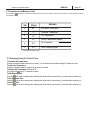
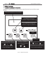
BLACK DECKER BD-137 Manuel utilisateur
- Catégorie
- Accessoires de piscine hors terre
- Taper
- Manuel utilisateur

Please read before returning this product for any reason.
INSTRUCTION MANUAL
CATALOG NUMBERS
BD

TABLE OF CONTENTS
EQUIPMENT INFORMATION RECORD
DATE OF INSTALLATION
INSTALLER INFORMATION
NOTES:
Page 2 ENGLISH Installation & Operation Manual
1.
Important Safety Instructions .............................
2.
2.1 Introduction .......................................................
2.2 Heat Pump Overview ........................................
2.3 Heat Pump Structure ........................................
3.1 Location .............................................................
3.2 Piping .................................................................
3.3 Electrical Requirements ...................................
3.4 Bonding .............................................................
4.3 Operating Using the Control Panel..................
4.4 Servicer Analyzer Codes...................................
4.5 Initial Startup .....................................................
5. Winterizing ..........................................................
6.1
Requesting Assistance or Service...................
7. Troubleshooting .................................................
8. Limited Warranty ................................................
3
General Information ...........................................
5
2.4 Heat Pump Components ...............................67
3. Installation............................................................8
8
9
13
14
15
15
15
16
17
8
6. Service .................................................................15
4
4
4
3.5 Electrical Wiring .........................................
4.
Operating the Pump .............................................
4.1 Control Panel Components ..............................
4.2 Parameters and Measure Value .......................
1011
12
12
13
8

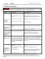
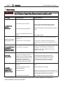
Definitions: Safety Alert Symbols and Words
This instruction manual uses the following safety alert symbols and words to alert you to hazardous situations
and your risk of personal injury or property damage.
DANGER: Indicates an imminently hazardous situation which, if not avoided, will result in death or serious injury.
WARNING: Indicates a potentially hazardous situation which, if not avoided, could result in death or serious injury.
CAUTION: Indicates a potentially hazardous situation which, if not avoided, may result in minor or moderate injury.
(Used without word): Indicates a safety related message.
NOTICE: Indicates a practice not related to personal injury which, if not avoided, may result in property damage.
1. Important Safety Instructions
When using electrical appliances, basic precautions should always be followed, including the following:
READ ALL INSTRUCTIONS BEFORE USING THE APPLIANCE.
WARNING:
Read all safety warnings and all instructions. Failure to follow the warnings and instructions listed
below may result in electric shock, fire, and/or serious injury.
To reduce the risk of injury, do not permit children to use or climb on this product.
Improper installation will create an electric hazard which could result in death or serious injury to pool
users, installers, or others due to electrical shock, and may also cause damage to property.
Risk of electric shock.
This heat pump is for use with 230Vrms nominal, and in pool heat pump applications ONLY.
Connection to the wrong voltage, or use in other application may cause damage to equipment or
personal injury.
Always disconnect power to the pool heat pump at the circuit breaker before servicing the heat pump.
Failure to do so could result in death or serious injury to serviceman, pool users, or others due to
electric shock.
All electrical wiring MUST be in conformance with all applicable local codes, regulations, and the
National Electric Code® (NEC®).
In accordance with the National Electric Code® (NEC®), this unit must be connected only to a supply
circuit that is protected by a ground-fault circuit-interrupter (GFCI).
To reduce the risk of electrical shock, replace any damaged cord immediately.
Page 3
Installation & Operation Manual ENGLISH

Page 4 ENGLISH Installation & Operation Manual
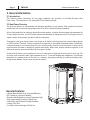
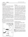
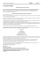
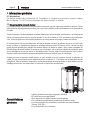
2. General Information
2.1 Introduction
This manual contains information for the proper installation and operation of the Black & Decker Heat
Pump family. The instructions in this manual MUST be followed precisely.
2.2 Heat Pump Overview
The pool heat pump is a self-contained unit designed specifically for pool heating. Each component has been
selected with care to achieve a high-quality product in an effort to exceed all industry standards.
All pool heat pumps have an electronic board with service analyzer, a titanium heat exchanger tube warranteed for
10 years against corrosion, and a PVC plastic cabinet that eliminates all maintenance for life. All components are of
superior quality, which presents you with an effective heat pump.
Compared to other types of pool heaters, such as gas or oil-fired, the pool heat pump has a lower heating capacity
on a BTU/hr basis. Therefore, it needs to operate for a longer time to accomplish the desired results. Occasionally,
it may be necessary to run the heat pump for up to 24 hours per day. However, this should not be of concern to the
owner because the heater is designed to operate continuously. What's more, despite continuous operation, it will
still heat the pool far more economically than other types of heaters.
As with all pool heaters, you are advised to use a pool solar cover at night and when the pool is not in use. The
pool solar cover should be used if night temperatures are 15° F less than desired pool temperature. This will keep
evaporation, the greatest source of heat loss, to a minimum, thus greatly reducing the overall pool heating costs.
During warmer weather, the pool cover may not be required.
General Features
• Utilizes Warm Ambient Air for Increased Efficiency
• BT Certified for Long-term Reliability
• Exclusive Self-Diagnostics to Keep Performance High
• Easy Programming Controls for Optimal Use
• Quiet Motor and Consumer-Friendly Installation
• Voltage: 208230V
• For Above Ground and Inground Pool Use

Page 5
Installation & Operation Manual ENGLISH
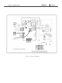
2. Heat tte
30
31
32

Page 6 ENGLISH Installation & Operation Manual
9
10
11
12
13
14
15
16
17
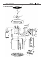
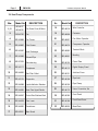
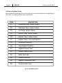
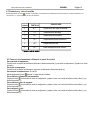
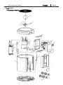
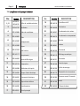
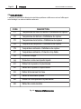
No.
18
19
20
21
22
23
24
25
26
27
28
29
30
31
32
DESCRIPTION
Wire Controller
Contactor
Fan Motor Capacitor
Compressor Capacitor
Terminal Block
Bonding
Cover Plate
Digital Display Panel
oint-box Cover
Pipe oint
Pipe Clamp
Union Connection Set
Front Panel
Front Panel Cover
Base Plate
2. Heat et
DESCRIPTION
Fan Grate Cover & Motor
Fan
Fan Frame
Filter Screen
Heat Exchanger
Exhaust Pipe
Gas-returning
Compressor
Gas Filter Outlet
Evaporator
Liquid-distributor
Stainless
Steel Plate Upper
Electric
Control Box
Stainless Steel
Plate Lower
Transformer
Main Board
e
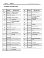
BD 44318
BD 44059
BD 44067
BD 44075
BD 44083
BD 44091
BD 44105
BD 44113
BD 44121
BD 44148
BD 44156
BD 44172
BD 44180
BD 44199
BD 44202
e .
BD 42730
BD 42889
BD 42897
BD 43087
BD 43095
BD 07323
BD 43117
BD 44636
BD 43176
BD 44598
BD 44555
BD 44547
BD 44539
BD 44520
BD 44326
BD 42617
BD 42676

Page 7
Installation & Operation Manual ENGLISH
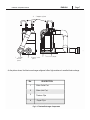
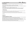
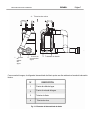
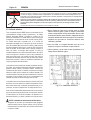
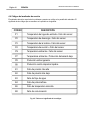
As the picture shows, the titanium exchanger refrigerant offers high resistance to excellent heat exchange.
No. DESCRIPTION
2
3
4
Water Outlet Port
Water Inlet Port
Titanium Pipe
Copper Pipe
1
Fig. 2.1: Titanium Echanger Components

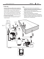
3. Installation
3.1 Location
1. The placement of the pool heater is very important in
keeping installation costs to a minimum while providing for
maximum efficiency of operation, as well as allowing
adequate access for service and maintenance.
2. The pool heat pump is designed for outdoor installation and
should not be installed in a fully enclosed area, such as a
shed, garage, etc. Recirculation of cold discharged air back
into the evaporator coil will greatly reduce unit heating
capacity and efficiency.
3. The unit should be located as close as practical to the
existing pool pump and filter to minimize water piping.
However, do not forget to provide a 24" clearance at the
very least all around your heat pump. The use of 90 degree
bends and short radius elbows in the water piping should
be kept to a minimum.
4. Mount the unit on a sturdy base, preferably a concrete slab
or a set of blocks. The base should be completely isolated
from the building foundation wall to prevent the possibility of
sound or vibration transmission into the building. The size
of the base should not be less than the size of the heat
pump.
Page 8 ENGLISH Installation & Operation Manual
te Air is pulled through the evaporator. Minimum clearance
of 72 inches should be allowed above air discharge. The unit
must not be installed under a porch. Any side of the unit
should be located at least 24 inches from obstructions for a
unrestricted air intake and service access.
3.2 Piping
1. The piping sequence is as follows: pool > pool pump >
filter > heater > corrosion-resistant check valve > chemical
feeder > pool. Automated chlorine distribution systems, if
used, must be placed downstream of the heater to
minimize harm to the pool equipment. Use rigid PVC
piping if possible.
2. All joints should be glued with PVC glue. When the piping
installation is complete, operate the pool pump and check
the system for leaks. Then, check the filter pressure gauge
to verify that there isn't any indication of excessive pump
head pressure.
You can also make the connections using high-pressure
flexible hose, but make sure the hose can withstand high
pressure.
3. The installation of a heat pump bypass is not necessary
unless the water flow exceeds 75 GPM.
te Certain installations have valves which isolate the
heat pump from the water circuit. If the heat exchanger is
deprived of water circulation for several days, high chlorine
gas could cause excessive corrosion. If the disconnect
switch is turned off, be sure that the pool water is allowed to
circulate through the unit, or is drained out of it.
3. Electrical Requirements
1. Install all equipment in accordance with the National
Electrical code and all applicable local codes and
ordinances.
2. The wiring of your pool heat pump should be performed
by a qualified licensed electrician in accordance with local
requirements. A properly-sized breaker and copper wire
must be used. Check the heat pump data label for
required maximum breaker size.
3. A means for disconnection must be incorporated in the
fixed wiring in accordance with the wiring rules.
Power to the unit, such as through a
breaker or external switch, must be turned off before
opening the access panel. Ensure that the unit has no
power BEFORE opening the access panel for any reason.
WARNING:

Page 9
Installation & Operation Manual ENGLISH
3.
1. Because all metals have different electrical potentials, all
metal and electrical components of the pool system must
be bonded together. This includes the metal framework of
the pool, the light, the pump, the filter (if made out of
metal), the heater, any automatic chlorine generator, and
any other metal or electrical equipment. On some older
pools, this substructure bond wire may not exist. In these
cases, a 6 to 8 foot solid copper rod must be driven into
the ground near the equipment.
2. All electric and metal components must then be bonded
to each other, and then to the copper rod. Contact a
licensed electrician.
te
A corrosion-resistant check valve is required for any
installation into a system with a sanitizer plumbed in with the
equipment. Failure to use a check valve that is corrosion-
resistant may void any future warranty claims.
Any kind of automatic chlorine distribution system must be
installed after the heat pump.
The filter must be placed before the heat pump.
A 3x ball or 2x diverter valve bypass and shut-off should be
installed on all systems for ease of service, maintenance and
to balance the water flow. Bypasses must be installed on any
system with over a 3/4 HP pool pump.

RISK OF ELECTRICAL SHOCK OR ELECTROCUTION. The Electric Heat Pump must be installed by a
licensed or certified electrician or a qualified service professional in accordance with the National Electrical
Code and all applicable local codes and ordinances. Improper installation will create an electrical hazard which
could result in death or serious injury to users, installers, or others due to electrical shock, and may also cause
damage to property.
Always disconnect power to the eat pump at the circuit breaker before servicing the eat pump.
Failure to do so could result in death or serious injury to service people, pool users, or others due to
electric shock and/or property damage.
Read all servicing instructions before working on the pump.
WARNING
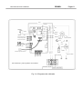
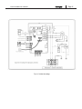
3.5 eta
All electrical wiring MUST be in conformance with all
applicable local codes, regulations, and the National Electric
Code® (NEC®). Contact a qualified electrician if you cannot
verify that the circuit is protected by a GFCI. The unit must
be connected only to a supply circuit that is protected by a
ground-fault circuit-interrupter (GFCI). Such a GFCI should
be provided by the installer and should be tested on a
routine basis. To test the GFCI, push the test button. The
GFCI should interrupt power. Push the reset button. Power
should be restored. The GFCI is defective if the GFCI fails
to operate in this way. If the GFCI interrupts power to the
pump without the test button being pushed, a ground current
is owing, indicating the possibility of an electric shock. Stop
using this pump. Disconnect the pump and ask a qualified
professional to correct the problem before using.
The pump accepts 230V, 50, or 60Hz single phase input
power. The terminal block connections are capable of
handling up to 12AWG solid or stranded wire. There are
also fast-on type quick connectors, however, check the local
electrical codes for the desired connection method. The
connections must be permanently made to the grounding
terminal (see Figure 4) in the field wiring compartment
according to the local electrical code.
The drive will operate on 2-phase Line-Line-Ground
electrical systems as well as Line-Neutral-Ground systems.
This pump must be permanently connected by a circuit
breaker as specified in the local electrical code.
To connect the electricity, you must unscrew the two screws
under the front panel, then slide the electric cable through
the knock out located on the left or the right side of the
base, and then insert it in the control box.
WARNING:RISK OF ELECTRIC SHOCK.
1. Be sure all electrical breakers and switches are turned off
before wiring motor. Always wait five (5) minutes after
disconnecting the power from the pump before opening or
servicing the drive.
3. Cut wires to the appropriate length so they do not overlap
or touch when connected to the terminal board.
4. Use the correct wire size and type specified by the current
National Electrical Code.
Page 10 ENGLISH Installation & Operation Manual
Choose a wire size for the pump in accordance with the
current National Electrical Code and all applicable local
codes and ordinances. When in doubt use a heavier gauge
(larger diameter) wire. Be sure the wiring voltage is within
the operating range.Be sure all electrical connections are
clean and tight.
2.

Page 11
Installation & Operation Manual ENGLISH

Page 12 ENGLISH Installation & Operation Manual
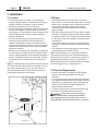
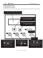
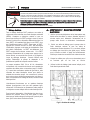
.eat te
t ae et
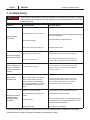
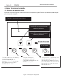
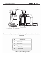
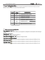
The control panel is factory set to display the temperature in Fahrenheit degrees, it can also be displayed as degree centigrade.
Heating
Temperature and Parameter Display Screen
To LOWER the Desired Temperature
or to Change Parameters
To RAISE the Desired Temperature
or to Change Parameters
Display Light
Switch On/O
Timer which Sets and
Adjusts the Shutdown Time
with the “ and ”
Buttons.
The Timer which Sets and Adjusts
the Running Time with the
“ and ” Buttons.
Long Press it for 10s to
Change “F” or “C” Display.
Clock Setting and Adjusting
with the “ and ” Buttons.
Long Press the key for 10s to Check
the Temperature Parameters
with Temperature Sensor.

4. aaete a eae ae
Long press the button for 10 seconds to examine the running parameters, change the item with the ^and v buttons to check
the measure value.
4. Operating te t ae
Page 13
Installation & Operation Manual ENGLISH
ITEM
DISPLAY
MEANING
0
0
Inlet Water Temperature
1
1
Discharge Temperature
2
2
Coil Temperature
3
3
4
4
Suction Temperature Ambient
Air Temperature
5
5
Valve Opening Degree
Displays the measure value
eae te eeate
Proceed as explained above using the up arrow (^) to increase the temperature setting 0.5 degree at a time.
e te eeate
Proceed as explained above, using the down arrow (v) instead.
a te eeate
Long press the key for 10 seconds to switch.
et e
Press the key to enter setting mode, adjusting the value with the up arrow key (^) and the down arrow key (v).
et t e
Press the key to enter setting mode, adjusting the value with the up arrow key (^) and the down arrow key (v).
et te
Press the key to enter setting mode, adjusting the value with the up arrow key (^) and the down arrow key (v).

Page 14 ENGLISH Installation & Operation Manual
Most problems will be detected by the service analyzer and a code will be displayed on the digital display of
your heater. The meaning of Display Codes are as follows:
CODE DESCRIPTION
P1 Inlet Water Temp • Sensor Failure
P2 Discharge Temp • Sensor Failure
P3 Coil Temp • Sensor Failure
P4 Suction Temp • Sensor Failure
PS Ambient Temp • Sensor Failure
P7 Ambient Temp • Too Low Protection
P8 Anti-freeze Protection
pg Liquid Impact Protection
E1 Highest Pressure Fault
E2 Lowest Pressure Fault
E3 Water Flow Fault
E4 Power/Phase Fault
E6 Highest Temperature Fault
E8 Communication Fault
ee ae e
4.2 e ea ae

.te
• First, you must turn the breaker off. The unit must be drained of all its water. You will need to disconnect the IN and OUT
water connections. Then the unit must be tilted or blown out with air until all water is out.
• The next step is to reconnect your IN and OUT water connections that will have previously been drained.
• It is recommended to cover the heat pump to prevent snow from getting inside. A protective winter cover is also offered by
your retailer.
Page 15
Installation & Operation Manual ENGLISH
ta tat
• Before starting the pool heater for the first time, it is important to verify that the breaker is in the ON position.
• Also make sure that the water circulates freely and that the pool pump is activated.
• Then, you will need to set the water temperature you desire. The fan will immediately start. The compressor will start after a 3
to 4 minute delay.
• When the compressor is running, the "heating" indicator located on the right
(see "Service Analyzer Control," p. 13) should be lit. At initial startup, it is normal for the unit to run 24 hours a day.
•It is also normal to see water dripping from the holes at the base of the unit. This is just condensation.
• All service will be handled by an Authorized Service Center. Warranty may be voided if service is not done by an Authorized
Service Representative. Do not return the heater to your dealer as they do not provide service.
• Before calling for assistance or service, please check the "Troubleshooting" (page 16) and "Warranty" (page 17) sections or
call your dealer. It may save you the cost of a service call. If you still need help, follow the instructions below.
• When asking for help, please provide a detailed description of the problem, your heater's complete model and serial number,
and the purchase date. This information will help us respond properly to your request.
• Keep a copy of the sales receipt showing the date of purchase. Proof of purchase will assure you warranty service.
ee
eet tae ee

Page 16 ENGLISH Installation & Operation Manual
7. Troubleshooting
a eta t a ee e teat t e t t et
tat ae eee t eett tat t eett a ae eat ea et
aae e tet te eat at eett e ae a
ee ea
WARNING
Problem Possible Cause Corrective Action
e eate
t
Heat pump control set to OFF.
Desired water temperature is reached.
Filter is dirty, restricting the water flow.
Turn the heat pump on.
e a t
te e t
Heat pump is in protection mode.
The unit is on defrost cycle.
In this case, there may be a delay before restarting.
The compressor will automatically start again a few
minutes until it has stopped three times continuously.
ee a a
te a t
t te e
Problem with power supply. Ask your electrician to verify your heat pump's power
supply by checking over the L1/L2/L3 connections in
the unit's service box.
ee ate
a te t
To check if the water really is a leak, you must stop
the heater and leave the pool pump running for over
5 hours. If water is still coming out of your heater
after this period, call your dealer for service.
e eate
t ee ate
teeate at
e eae
Main breaker is tripped.
Unit will automatically restart when the water temperature goes
below the set temperature.
Reset main breaker and restart heat pump.
Backwash and clean filter.
While your pool heater is in the heating
mode, a large quantity of warm and
humid air passes over the evaporator
and causes condensation. It is normal to
see condensation dripping under the
heater.
Heat loss is too much for heater. Cover your pool as often as possible with solar cover.
Evaporator restricted due to improper
location.
Correct the location of the pool heater.
Evaporator is dirty. Clean it by running tap water over the coil without additional
nozzle attachment. Do not use pressurized water as it can
damage the coil and void warranty.
Restricted water flow. Adjust water flow. Check bypass.
If your pool heater does not operate for reasons other than those mentioned above, please contact Consumer
Assistance Center to obtain the proper authorization for the warranty to apply.

Page 1
Installation & Operation Manual ENGLISH
8. Limited Warranty
Service Information
The Pump Service Center is staffed with trained personnel to provide customers with efficient and reliable pool service.
Whether you need technical advice, repair, or genuine factory replacement parts, contact the Pump Service Center. Call:
(516) 796-2425 or visit [email protected]/[email protected].
Blue Torrent Pool Products Limited Warranty
Limited Five-Year Warranty
Blue Torrent Pool products warrants this product to be free from defects in material or workmanship for a period of five (5) years
following the date of purchase.
This limited warranty does not cover failures due to abuse, accidental damage, or when repairs have been made or attempted
by anyone other The Authorized Pump Service Centers.
A defective product meeting the guarantee conditions set forth herein will be replaced or repaired at no charge in either of two
ways:
The first, which will result in exchanges only, is to return the product to the retailer from whom it was purchased (provided that
the store is a participating retailer). Returns should be made within the time period of the retailer’s policy for exchanges. Proof
of purchase may be required.
Please check with the retailer for its specific return policy regarding time limits for returns or exchanges.
The second option is to take or send the product (prepaid) to the authorized Pump Service Center for repair or replacement at
Blue Torrents Option option. Proof of purchase may be required.
Pump Service Center
(516) 796-2425
1075 Hicksville Road
Seaford, NY 11783 USA
This limited warranty constitutes the entire warranty. No other warranties apply, expressed or implied. This warranty gives you
specic legal rights and you may have other rights which vary from state to state. Should you have any questions, contact the
manager of the Pump Service Center.
LATIN AMERICA: This warranty does not apply to products sold in Latin America. For products sold in Latin America, check
country specific warranty information contained in the packaging, call the local company, or see the website for such
information.
FREE WARNING LABEL REPLACEMENT: If your warning labels become illegible or are missing, call (516) 796-2425 for a
free replacement.
Manufactured by Blue Torrent Pool Products
444 E 81ST ST
NEW YORK,NY 10028-5859
BLACK & DECKER, BLACK+DECKER, the BLACK & DECKER and BLACK+DECKER
logos and product names and the orange and black color scheme are trademarks of
The Black & Decker Corporation, used under license. All rights reserved.
Patents/Protege/Patentes: www.blackanddecker.com/patents
© Copyright

Por favor, lea este manual antes de devolver el producto por cualquier motivo.

Página 2
ESPAÑOL
Manual de instrucciones e instalación
CONTENIDO
1. Instrucciones importantes de seguridad ...........
3
2. Información general ........................................ 4
2.1 Introducción ................................................. 4
2.2 Resumen de la bomba de calor ......................
4
2.3 Estructura de la bomba de calor ..................... 5
2.4 Elementos de la bomba de calor ................. 6–7
3. Instalación. ...................................................... 8
3.1 Ubicación ...................................................... 8
3.2 Tuberías ........................................................ 8
3.3 Requisitos eléctricos ..................................... 8
3.4 Unión ............................................................. 9
3.5 Cableado eléctrico ..................................
10–11
4. Hacer funcionar la bomba ............................... 12
4.1 Elementos del panel de control ..................... 12
4.2 Parámetros y valor de medida ....................... 13
4.3 Poner en funcionamiento utilizando el panel de
control .......................................................... 13
4.4 Códigos del analizador de servicio. ............... 14
4.5 Primera puesta en marcha ............................ 15
5. Preparación para el invierno ............................ 15
6. Servicio técnico ............................................... 15
6.1 Solicitar asistencia o servicio técnico ........... 15
7. Solución de problemas .................................... 16
8. Garantía limitada ............................................. 17
FECHA DE INSTALACIÓN
INFORMACIÓN DEL INSTALADOR
NOTAS:
INFORMACIÓN DE REGISTRO DEL EQUIPO

ESPAÑOL
Página 3
Manual de instrucciones e instalación
Definiciones: Símbolos y palabras de aviso de seguridad
Este manual de instrucciones utiliza los siguientes símbolos y palabras de aviso de seguridad para advertirle de
situaciones peligrosas y del riesgo a lesiones personales o daños materiales.
PELIGRO: Indica una situación de peligro inminente que, si no se evita, tendrá como consecuencia la muerte o
lesiones graves.
AVISO: Indica una situación potencialmente peligrosa que, si no se evita, podría tener como consecuencia la
muerte o lesiones graves.
PRECAUCIÓN: Indica una situación potencialmente peligrosa que, si no se evita, puede tener como
consecuencia lesiones leves o moderadas.
(Sin palabra): Indica un mensaje de seguridad.
NOTA: Indica una práctica no relacionada con una lesión personal que, si no se evita, puede dar
lugar a daños materiales.
1. Instrucciones importantes de seguridad
Siempre se deben seguir las precauciones básicas de seguridad al utilizar aparatos eléctricos, entre las
que se incluyen: LEER TODAS LAS INSTRUCCIONES ANTES DE UTILIZAR EL APARATO.
AVISO:
•
Lea todas las advertencias de seguridad e instrucciones. No seguir las advertencias e
instrucciones que se mencionan a continuación puede tener como consecuencia descargas
eléctricas, incendios y/o lesiones graves.
•
Para reducir el riesgo de sufrir lesiones, no permita que los niños utilicen o se suban a este producto.
•
Una instalación inadecuada dará lugar a un riesgo eléctrico que podría causar la muerte o serias
lesiones para los usuarios de piscinas, instaladores u otras personas, debido a una descarga eléctrica.
También puede causar daños materiales.
•
Riesgo de descarga eléctrica.
•
Esta bomba de calor se utiliza con 230Vrms nominal y SOLAMENTE como bomba de calor
para piscinas. La conexión al voltaje equivocado, o su uso en otra aplicación, puede causar
daños al equipo o lesiones personales.
•
Desconecte en todo momento el suministro eléctrico de la bomba de calor para piscinas en el
interruptor antes de realizar ninguna reparación o mantenimiento en ella. De no hacerlo, podría tener
como consecuencia la muerte o lesiones graves para el técnico, las personas que utilicen la piscina
u otros por descarga eléctrica.
•
Todo el cableado eléctrico DEBE estar en conformidad con todos los códigos locales
correspondientes, regulaciones y el Código Eléctrico Nacional® (NEC®).
•
De conformidad con el Código Eléctrico Nacional ® (NEC®), esta unidad solo debe conectarse a un
circuito de alimentación protegido por un interruptor de circuito por falla a tierra (GFCI).
•
Para reducir el riesgo de descargas eléctricas, sustituya inmediatamente cualquier cable dañado.
La page est en cours de chargement...
La page est en cours de chargement...
La page est en cours de chargement...
La page est en cours de chargement...
La page est en cours de chargement...
La page est en cours de chargement...
La page est en cours de chargement...
La page est en cours de chargement...
La page est en cours de chargement...
La page est en cours de chargement...
La page est en cours de chargement...
La page est en cours de chargement...
La page est en cours de chargement...
La page est en cours de chargement...
La page est en cours de chargement...
La page est en cours de chargement...
La page est en cours de chargement...
La page est en cours de chargement...
La page est en cours de chargement...
La page est en cours de chargement...
La page est en cours de chargement...
La page est en cours de chargement...
La page est en cours de chargement...
La page est en cours de chargement...
La page est en cours de chargement...
La page est en cours de chargement...
La page est en cours de chargement...
La page est en cours de chargement...
La page est en cours de chargement...
La page est en cours de chargement...
La page est en cours de chargement...
-
 1
1
-
 2
2
-
 3
3
-
 4
4
-
 5
5
-
 6
6
-
 7
7
-
 8
8
-
 9
9
-
 10
10
-
 11
11
-
 12
12
-
 13
13
-
 14
14
-
 15
15
-
 16
16
-
 17
17
-
 18
18
-
 19
19
-
 20
20
-
 21
21
-
 22
22
-
 23
23
-
 24
24
-
 25
25
-
 26
26
-
 27
27
-
 28
28
-
 29
29
-
 30
30
-
 31
31
-
 32
32
-
 33
33
-
 34
34
-
 35
35
-
 36
36
-
 37
37
-
 38
38
-
 39
39
-
 40
40
-
 41
41
-
 42
42
-
 43
43
-
 44
44
-
 45
45
-
 46
46
-
 47
47
-
 48
48
-
 49
49
-
 50
50
-
 51
51


BLACK DECKER BD-137 Manuel utilisateur
- Catégorie
- Accessoires de piscine hors terre
- Taper
- Manuel utilisateur
dans d''autres langues
- English: BLACK DECKER BD-137 User manual
- español: BLACK DECKER BD-137 Manual de usuario
Autres documents
-
Raypak 40-I-M Manuel utilisateur
-
Aquacal AUTOPILOT 120 Manuel utilisateur
-
Zodiac Edenpac 5D Instructions For Installation And Use Manual
-
-
Waterco Electroheat Pool Heat Pump Mode d'emploi
-
Polaris PB4-60 Mode d'emploi
-
Jandy AquaLink RS Control Systems Manuel utilisateur
-
 Nautyl PHCP50 Installation and User Manual
