Jandy AquaLink RS Control Systems Manuel utilisateur
- Taper
- Manuel utilisateur

Hardware Installation Manual
Manuel d’installation du matériel
Manual de instalación del hardware
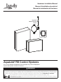
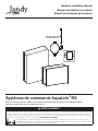
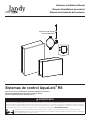
AquaLink®
RS Control Systems
For use with Pool/Spa Combination, Pool Only/Spa Only, and Dual Equipment
AquaLink RS Systems with Rev Y Firmware
WARNING
FOR YOUR SAFETY – This product must be installed and serviced by a contractor who is licensed and qualified in pool equipment by the jurisdiction in which the product will be installed
where such state or local requirements exist. The maintainer must be a professional with sufficient experience in pool equipment installation and maintenance so that all of the instructions
in this manual can be followed exactly. Before installing this product, read and follow all warning notices and instructions that accompany this product. Failure to follow warning notices
and instructions may result in property damage, personal injury, or death. Improper installation and/or operation may void the warranty. DO NOT MODIFY THIS EQUIPMENT.
Improper installation and/or operation can create unwanted electrical hazard which may cause serious injury, property damage, or death.
ATTENTION INSTALLER – This manual contains important information about the installation, operation and safe use of this product. This information should be given
to the owner/operator of this equipment.
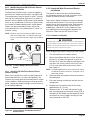
iAquaLink
Web-Connected
Device

Page 2
ENGLISH AquaLink® RS Control Systems | Hardware Installation Manual
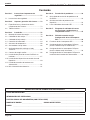
Table of Contents
EQUIPMENT INFORMATION RECORD
DATE OF INSTALLATION _______________________________________________________________________________
INSTALLER INFORMATION _____________________________________________________________________________
INITIAL PRESSURE GAUGE READING (WITH CLEAR FILTER) ____________________________________________
PUMP MODEL ________________________________ HORSEPOWER ____________________________________
NOTES _______________________________________________________________________________________________
______________________________________________________________________________________________
______________________________________________________________________________________________
Section 1. Important Safety Instructions ........3
1.1 Safety Instructions .........................................3
Section 2. System Overview .............................5
2.1 System Component Specifications and
Dimensions .....................................................5
2.2 Basic Plumbing ..............................................6
Section 3. Installation ........................................ 8
3.1 Power Center Mounting .................................8
3.2 High Voltage Wiring ........................................ 8
3.3 Low Voltage Wiring ......................................13
3.4 Heater Connection .......................................16
3.5 Temperature Sensors ...................................18
3.6 Jandy Valve® Actuators ................................18
3.7 Jandy TruSense Water Chemistry
Analyzer ........................................................18
3.8 Auxiliary Power Centers ...............................19
3.9 OneTouch Control Panel Indoor
Installation ....................................................19
3.10 iAquaLink Web-Connected Device
Installation ....................................................21
3.11 Powered Hardware Connection Test: ...........24
3.12 Further Reference Information .....................24
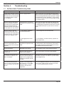
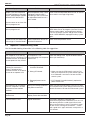
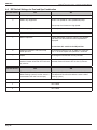
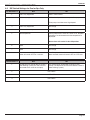
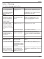
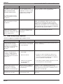
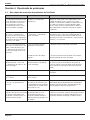
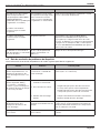
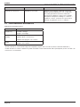
Section 4. Troubleshooting .............................25
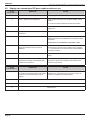
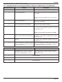
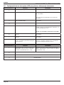
4.1 OneTouch Quick Troubleshooting Guide .....25
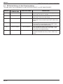
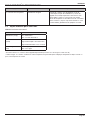
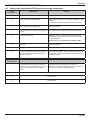
4.2 iAquaLink Troubleshooting Guide ...............26
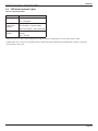
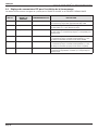
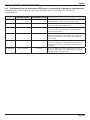
4.3 LED Status Indicator Lights .........................27
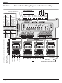
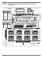
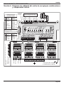
Section 5. Power Center Wiring Diagram for
Combos and Onlys ........................28
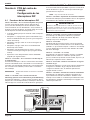
Section 6. Power Center PCB
DIP Switch Settings .......................29
6.1 DIP Switch Functions ................................... 29
6.2 DIP Switch Settings for Pool and Spa
Combination .................................................30
6.3 DIP Switch Settings for Pool or Spa Only .... 31
6.4 DIP Switch Settings for Heat Pump
Installation ....................................................32

Page 3
AquaLink® RS Control Systems | Hardware Installation Manual ENGLISH
Section 1. Important Safety Instructions
READ AND FOLLOW ALL INSTRUCTIONS
1.1 Safety Instructions
All electrical work must be performed by a licensed electrician and conform to all national, state, and local
codes. When installing and using this electrical equipment, basic safety precautions should always be
followed, including the following:
WARNING
To reduce the risk of severe injury or death, do not remove the suction fittings of your spa or hot tub. Never operate a spa or hot tub if the suction
fittings are broken or missing. Never replace a suction fitting with one rated less than the flow rate marked on the equipment assembly.
WARNING
Prolonged immersion in hot water may induce hyperthermia. Hyperthermia occurs when the internal temperature of the body reaches a level several
degrees above the normal body temperature of 98.6°F (37°C). The symptoms of hyperthermia include dizziness, fainting, drowsiness, lethargy, and
an increase in the internal temperature of the body. The effects of hyperthermia include: 1) unawareness of impending danger; 2) failure to perceive
heat; 3) failure to recognize the need to exit spa; 4) physical inability to exit spa; 5) fetal damage in pregnant women; 6) unconsciousness resulting in
a danger of drowning; 7) The use of alcohol, drugs, or medication can greatly increase the risk of fatal hyperthermia in hot tubs and spas. less than
the flow rate marked on the equipment assembly.
WARNING
To Reduce the Risk of Injury -
• The water in a spa should never exceed 104°F (40°C). Water temperatures between 100°F (38°C) and 104°F (40°C) are considered safe for a
healthy adult. Lower water temperatures are recommended for young children and when spa use exceeds 10 minutes.
• Since excessive water temperatures have a high potential for causing fetal damage during the early months of pregnancy, pregnant or possibly
pregnant women should limit spa water temperatures to 100°F (38°C).
• Before entering a spa or hot tub, the user should measure the water temperature with an accurate thermometer since the tolerance of water
temperature-regulating devices varies.
• The use of alcohol, drugs, or medication before or during spa or hot tub use may lead to unconsciousness with the possibility of drowning.
• Obese persons and persons with a history of heart disease, low or high blood pressure, circulatory system problems, or diabetes should consult
a physician before using a spa.
• Persons using medication should consult a physician before using a spa or hot tub since some medication may induce drowsiness while other
medication may affect heart rate, blood pressure, and circulation.
WARNING
Risk of electric shock, which could result in severe injury or death - Install the power center at least five (5) feet (1.52m)
from the inside wall of the pool and/or hot tub using non-metallic plumbing. Canadian, Australian, and European installations must be at least three
(3) meters from the water.
Children should not use spas or hot tubs without adult supervision.
Do not use spas or hot tubs unless all suction guards are installed to prevent body and hair entrapment.
People using medications and/or having an adverse medical history should consult a physician before using a spa or hot tub.

Page 4
ENGLISH AquaLink® RS Control Systems | Hardware Installation Manual
WARNING
People with infectious diseases should not use a spa or hot tub.
To avoid injury, exercise care when entering or exiting the spa or hot tub.
Do not use drugs or alcohol before or during the use of a spa or hot tub to avoid unconsciousness and possible drowning.
Do not use a spa or hot tub immediately following strenuous exercise.
Prolonged immersion in a spa or hot tub may be injurious to your health.
Do not permit any electric appliance (such as a light, telephone, radio, or television) within 5 feet (1.52m) of a spa or hot tub.
The use of alcohol, drugs or medication can greatly increase the risk of fatal hyperthermia in hot tubs and spas.
WARNING
To avoid injury ensure that you use this control system to control only packaged pool/spa heaters which have built-in operating and high limit controls
to limit water temperature for pool/spa applications. This device should not be relied upon as a safety limit control. Water temperature in excess of
100°F (38°C) may be hazardous to your health.
WARNING
A terminal bar marked “GROUND” is provided within the power center. To reduce the risk of electrical shock, connect this terminal bar to the grounding
terminal of your electric service or supply panel with a continuous copper conductor having green insulation and one that is equivalent in size to the
circuit conductors supplying this equipment, but no smaller than no. 12 AWG (3.3mm2). In addition, a second wire connector should be bonded with a
no. 8 AWG (8.4mm2) copper wire to any metal ladders, water pipes, or other metal within five (5) feet (1.52m) of the pool/spa. In Canada, the bonding
wire must be minimum 6 AWG (13,3mm2).
WARNING
A ground-fault circuit-interrupter must be provided if this device is used to control underwater lighting fixtures. The conductors on the load side of the
ground-fault circuit-interrupter shall not occupy conduit, boxes, or enclosures containing other conductors unless the additional conductors are also
protected by a ground-fault circuit-interrupter. Refer to local codes for complete details.
Attention installer: Install to provide drainage of compartment for electrical components.
SAVE THESE INSTRUCTIONS
FCC Regulatory Compliance Statement
This device complies with Part 15 of the FCC Rules. Operation is subject to the following two conditions:
1. This device may not cause harmful interference, and
2. This device must accept any interference received, including interference that may cause undesired operation.
CAUTION: Changes or modifications not expressly approved by the party responsible for compliance could void the user's authority to operate
the equipment.
NOTE: This equipment has been tested and found to comply with the limits for a Class B digital device, pursuant to Part 15 of the FCC Rules.
These limits are designed to provide reasonable protection against harmful interference in a residential installation. This equipment generates, uses
and can radiate radio frequency energy and, if not installed and used in accordance with the instructions, may cause harmful interference to radio
communications. However, there is no guarantee that interference will not occur in a particular installation. If this equipment does cause harmful
interference to radio or television reception, which can be determined by turning the equipment off and on, the user is encouraged to try to correct
the interference by one or more of the following measures:
• Reorient or relocate the receiving antenna.
• Increase the separation between the equipment and receiver.
• Connect the equipment into an outlet on a circuit different from that to which the receiver is connected.
• Consult the dealer or an experienced radio/TV technician for help.

Page 5
AquaLink® RS Control Systems | Hardware Installation Manual ENGLISH
Section 2. System Overview
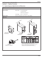
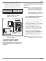
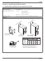
2.1 System Component Specifications and Dimensions
Specifications (USA and Canada)
Power Supply 120 VAC; 60 Hz; 3 A
Contact Rating High voltage - 25 A; 3HP @ 240 VAC
1½ HP @120 VAC
1500 Watts Incandescent
Low Voltage - Class 2, 1 A @ 24 VAC
Service Switch All Circuits (located at Power Center in Service Mode)
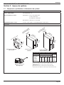
Dimensions
One TouchTM
Control Panel
14½”
® 1
® 2
® 3
® 4
® 5
1 Cutler-Hammer is a registered trademark of Cutler-Hammer, Inc.
2 Murray is a registered trademark of Briggs & Statton Corp.
3 Siemens is a registered trademark of Siemens Energy and Automation, Inc.
4 Square D is a registered trademark of Square D Company.
5 Thomas & Betts is a registered trademark of Thomas & Betts Corp.
iAquaLink
Web-Connected Device
14½”
Standard
Power Center Sub-Panel
Power Center
4½”
1¼”
(6” for PureLinkTM)
5”
5”
(6” for PureLink)
4½”
20”
13¼”

Page 6
ENGLISH AquaLink® RS Control Systems | Hardware Installation Manual
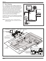
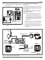
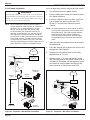
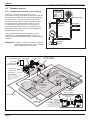
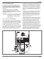
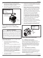
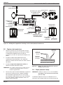
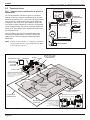
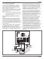
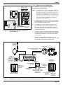
2.2 Basic Plumbing
2.2.1 Plumbing for Pool and Spa Combination
The intake and return JVA’s turn si mul ta neous ly so
when the spa button is pressed on the AquaLink RS
control panel, water circulation switches between
pool and spa (consult the Jandy Valve Actuator
Installation and Operation Manual to ensure that the
JVA’s are synchronized and rotate properly). Please
consult the Jandy Valve® Plumb ing Manual for
further examples of pool/spa plumbing.
For pool only/spa only or dual equipment plumbing,
please refer to the Jandy Valve Plumbing Manual for
further examples.
NOTE When the fi lter system is shared (a pool/spa
combo), the spa water must be able to overfl ow
back to the pool.
Pool
Drain
From Solar
To Solar
Heat Pump
Check
Valve
Heater
Filter
Pump
From Filter
To
Heater
To Spa
Figure 1. Heat Pump Plumbing
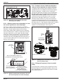
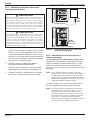
MAIN DRAINS
(Suction Outlet)
Optional
Cleaner Suction Port
MANUAL BYPASS VALVE
HEATER
FILTER
CHECK VALVE
(Check Valve recommended
for systems installed with Erosion Feeders
or Aquapure® salt chlorination systems)
PUMP POOL/SPA
3 WAY VALVE
SPA DRAIN
(Suction Outlet)
SKIMMER
SPA RETURN
POOL
RETURN
a.
a.
MANUAL BY-PASS DETAIL:
USE WHEN FILTRATION RATE EXCEEDS
125 GPM FOR ZODIAC HEATERS. REFER
TO THE MANUFACTURER’S
RECOMMENDATIONS IF USING A
DIFFERENT BRAND HEATER.
AUTOMATION
IAQUALINK
WEB-CONNECTED
DEVICE
S1
S2
RESET
SERVICE
TIME OUT
FILTERPUMP
AUX1
AUX 2
AUX3
AUX 4
AUX 5
AUX6
AUX7
RS6 & RS8 ONLY
RS8 ONLY
HEATER SOLAR
POOL MODE
SPA MODE
SPA DRAIN
SPA FILL
AUTO
654321
10987654321
43214321
TRUSENSE
LIGHTING
Figure 2. Typical Water Piping Confi guration

Page 7
AquaLink® RS Control Systems | Hardware Installation Manual ENGLISH
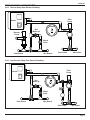
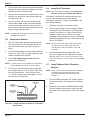
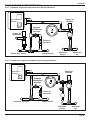
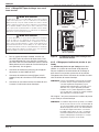
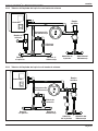
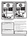
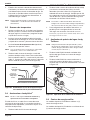
2.2.2 Booster Pump Pool Cleaner Plumbing
Heater
Booster
Pump
Pool Return Spa Return
Spa
Make-up
Check
Valve
Pool Intake Spa Intake
Filter
Pump
Filter
2.2.3 Non-Booster Pump Pool Cleaner Plumbing
Heater
Pool Return Spa Return
Spa
Make-up
Check
Valve
Pool Intake Spa Intake
Filter
Pump
Filter

Page 8
ENGLISH AquaLink® RS Control Systems | Hardware Installation Manual
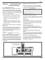
Section 3. Installation
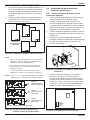
3.1 Power Center Mounting
1. The power center should be located at or near
the equipment pad. Locate the power center
at least five (5) feet or more away from pool/
spa and five (5) feet off the ground. All national,
state, and local codes are applicable.
NOTE For Canadian installations, the power center must
be at least three (3) meters (9.8 feet) away from
the pool/spa and 1.5 meters (5 feet) above the
ground.
2. Use the mounting brackets and instructions
provided with the standard power center and/or
sub-panel power center.
3. Sub-panel power centers have special code
requirements. Be sure to follow all applicable
local and state codes to insure safe installation.
NOTE The power center is not to be considered as
suitable for use as service equipment. Therefore,
it is required to have the appropriate means of
disconnection, circuit isolation, and/or branch
circuit protection installed upstream of the power
center.
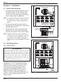
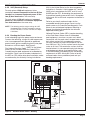
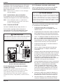
3.2 High Voltage Wiring
3.2.1 System Power
WARNING
Potentially high voltages in the AquaLink Power Center can create
dangerous electrical hazards, possibly causing death, serious injury or
property damage. Turn off power at the main circuit of the AquaLink
Power Center to disconnect the Power Center from the system. To
properly and safely wire the system, be sure to carefully follow the
applicable requirements of the National Electrical Code®
(NEC®), NFPA
70 or the Canadian Electrical Code (CEC®), CSA C22.1. All applicable
local installation codes must also be adhered to.
Depending on the amount of equipment being
controlled, run ½” or ¾” conduit from the power
supply panel to the bottom of the power center.
If you are using the sub-panel power center,
wire power to the appropriate breakers. Pull in
appropriate wire for equipment. Each piece of
equipment requires its own high voltage relay.
Connect 120 volts for US/CAN to the power center
terminals. Connect equipment ground(s). See
Figures 3 and 4.
Transformer
Primary
Black
White
Wire nut for
120 VAC power
Earth Ground
Neutral
Breaker Panel
To 120 VAC
Breaker
Low voltage raceway. Do not run high voltage in this compartment.
Figure 3. Standard Power Center
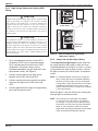
White
White
Black
Black
From
Main
Power
Ground
Transformer
Primary
Black
White
Earth Ground
Low voltage raceway. Do not run high voltage in this compartment.
Figure 4. Sub-Panel Power Center

Page 9
AquaLink® RS Control Systems | Hardware Installation Manual ENGLISH
3.2.2 3HP (Standard) Relays
For each piece of 240 volt equipment to be
controlled, connect line power to the two (2) line
terminals and connect equipment power to the
two (2) load terminals on the same relay.
For each piece of 120 volt equipment, connect
power to a line terminal and connect equipment
to a load terminal on the same relay.
NOTE The following are the contact ratings for 3HP
(Standard) Relay. DO NOT exceed any ratings.
3 HP @ 240 VAC; 1½ HP @ 120 VAC; 25 Amps;
1500 Watts.
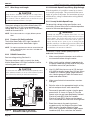
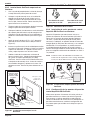
3.2.3 Bonding the Power Center
Install a bonding lug to the power center enclosure.
Connect the bond lug, using a #8 solid copper core
wire, to an approved earth ground (an approved
ground stake, grid, or conducting metal water pipe
buried to a sufficient depth). See Figure 5.
The National Electrical Code® (NEC® in the United
States) or the Canadian Electrical Code (CEC in
Canada) requires pool equipment to be bonded to
each other. Check your local codes to determine if
the NEC or CEC and/or other local installation codes
are enforced by the Authority Having Jurisdiction
(AHJ in the United States) or the local competent
authorities in Canada. A solid, copper 8.37 mm2 (8
AWG) wire is required per the NEC, and 13.3 mm²
(6AWG) per the CEC, for bonding the equipment to
a permanent bonding connection that is acceptable
to the local AHJ or the local competent authorities in
Canada.
Refer to your locally enforced codes for the
acceptable bonding wire gauge. Do not use the
power center as the common bonding point. Each
piece of non-related pool equipment requiring a
ground should also be bonded to the common
approved bonding point.
National Electrical Code® (NEC®) requires bonding
of the Pool Water. Where none of the bonded
pool equipment, structures, or parts are in direct
connection with the pool water; the pool water shall
be in direct contact with an approved corrosion-
resistant conductive surface that exposes not less
than 5800 mm² (9 in²) of the surface area to the pool
water at all times. The conductive surface shall be
located where it is not exposed to physical damage
or dislodgement during usual pool activities, and
it shall be bonded in accordance with the bonding
requirements of NEC Article 680. Refer to locally
enforced codes for any additional pool and spa
bonding requirements
Earth
Ground
Bonding
Lug
Breaker
Panel
Blower
(120 VAC)
Blower
(240 VAC)
24 VAC
Transformer
Primary
Figure 5. Standard Power Center - Bonding

Page 10
ENGLISH AquaLink® RS Control Systems | Hardware Installation Manual
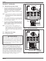
3.2.4 High Voltage Underwater Lighting GFCI
Wiring
CAUTION
A Ground Fault Circuit Interrupter (GFCI) must be provided in high
voltage pool/spa lights. The conductors on the load side of the GFCI
device shall not occupy conduit, boxes, or enclosures containing other
conductors unless the other conductors are also on the load side of
a GFCI, or unless the other conductors are segregated, separated by
barrier(s) or routed and secured to provide permanent spacing from
the conductors on the load side of the GFCI. Refer to local codes for
complete details.
CAUTION
The AquaLink RS system is for fixed installations only and to be
used in conjunction with swimming pool equipment. Also refer to the
installation instructions relating to the swimming pool equipment for
which the system will be an integral part. The system is to be supplied
through a residual current device (RCD) with a rated residual operating
current of 30mA. If the supply cord is damaged it must be replaced by
the manufacturer or its service agent or similarly qualified person in
order to avoid hazard.
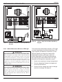
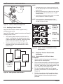
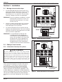
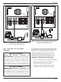
1. For a standard power center, install a GFCI
receptacle or RCD next to the breaker panel.
For a sub-panel power center install a GFCI
receptacle in the power center (use the
knockout provided on the right side of the sub-
panel power center). See Figure 6.
2. Connect neutral and hot wire (from circuit
breaker) to the LINE side of the GFCI.
3. Connect neutral (white wire) and the hot (black
wire) from the light to the LOAD side of the
GFCI.
4. Connect ground from the light to the grounding
bar inside the power center.
S1
S2
RESET
SERVICE
TIME OUT
FILTER PUMP
AUX1
AUX2
AUX3
AUX4
AUX5
AUX6
AUX7
RS6 & RS8 ONLY
RS8 ONLY
HEATER SOLAR
POOL MODE
SPA MODE
SPA DRAIN
SPA FILL
AUTO
6543 2 1
10 987 6 54321
4 3 2 1 4 3 2 1
OPTIONAL
GFCI
Outlet
Standard
Power Center
S1
S2
RESET
SERVICE
TIME OUT
FILTER PUMP
AUX1
AUX2
AUX3
AUX4
AUX5
AUX6
AUX7
RS6 & RS8 ONLY
RS8 ONLY
HEATER SOLAR
POOL MODE
SPA MODE
SPA DRAIN
SPA FILL
AUTO
654 3 2 1
10 9 8 7 6 5 4 3 2 1
4 3 2 1 4 3 2 1
OPTIONAL
GFCI Outlet
(optional)
Sub-Panel Power Center
Figure 6. GFCI Installation for High Voltage
Underwater Lighting
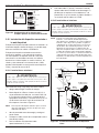
3.2.5 Jandy Pool and Spa Lights Wiring
The Jandy Pool and Spa Lights can be wired into
the Jandy AquaLink RS control system to ensure
simplified operation of the lights, as well as a means
to synchronize the color change function. Connect
the lights to one of the auxiliary relays in the power
center.
NOTE It is recommended to connect one (1) light per
relay so each light can be controlled separately.
However, up to four lights can be connected on
a single relay. If there are more than four (4) lights
installed on one AquaLink RS system, ensure
there is more than one (1) auxiliary relay available
in the Power Center.
Refer to Figures 7 and 8 to connect the Jandy pool
and spa lights to the power center.
NOTE The Jandy pool and spa lights are available
in 120-volt and 12-volt versions. If installing a
12-volt light, a 120-volt/12-volt step-down (AC)
transformer must be used. For more information
about 12-volt installations, refer to the Jandy
Digital,Color Changing,Underwater Pool and Spa
Lights Installation and Operation Manual.

Page 11
AquaLink® RS Control Systems | Hardware Installation Manual ENGLISH
GFCI
Black
White
Green
Ground
Ground
Neutral
120 VAC
Power Supply
Black
White
Green
JUNCTION
BOX
120V
Jandy
Light
Figure 7. 120-Volt Jandy Pool and Spa Light Wiring
Diagram
Ground
Neutral
120 VAC (US)
Power Supply
AquaLink
®
Aux
Black
GFCI*
120 volts to
12VAC
Transformer
White
Ground
Line
Black
Black
White
White
Green
Relay or Switch
*If required by transformer manufacturer's instructions or by local code and AHJ requirements.
Figure 8. 12-Volt Jandy Pool and Spa Light Wiring
Diagram
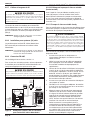
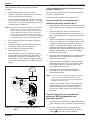
3.2.6 Infinite Watercolors Nicheless LED Light
WARNING
RISK OF ELECTRICAL SHOCK OR ELECTROCUTION,
which could result in serious injury or death. A Ground Fault Circuit
Interrupter (GFCI) for 120 Volt transformers should be used if required
by the transformer manufacturer or if required by the local applicable
code and/or Authority Having Jurisdiction (AHJ). When a GFCI is used,
the conductors on the load side of the GFCI circuit shall not occupy
conduit, boxes, or enclosures containing other conductors unless the
additional conductors are also protected by a GFCI. Refer to local codes
for complete details.
WARNING
RISK OF ELECTRICAL SHOCK OR ELECTROCUTION,
which could result in serious injury or death. The Jandy Infinite
WaterColors Nicheless LED Lights are only available for 14 Volt AC
power. For supply connection, use only an isolating low voltage power
supply with ungrounded output, evaluated and listed by a NRTL for
swimming pool use.
The Jandy Infinite WaterColors Nicheless LED Lights
must be controlled by the Infinite WaterColors LED
Light Controller and AquaLink automation system.
Refer to Figure 9 to connect the Jandy Infinite
WaterColors Nicheless LED Lights and to the
Infinite WaterColors LED Light Controller manual
for connecting the Infinite WaterColors LED Light
Controller to the AquaLink automation system.
1. Knock out an opening in the right compartment.
2. Run low voltage light through a cord grip and
secure to the enclosure
3. Connect the low voltage wires black to orange
and white to orange. See Figure 9.

Page 12
ENGLISH AquaLink® RS Control Systems | Hardware Installation Manual
3.2.7 Wire Gauge and Length
CAUTION
Jandy®
Nicheless Underwater LED Lights are low voltage fixtures.
Improper wire gauge and wire length can effect the performance of
these products. Follow the guidelines below to determine the proper
operation and optimum performance of the lights.
The output voltage of the Infinite WaterColors LED
Light Controller is 14 VAC to accommodate the
voltage drop across cords up to 200 ft. Installations
should not exceed 200 ft.
NOTE Each color mode has a slightly different power
draw
3.2.8 Fourteen (14) Volt Installation
The Infinite WaterColors LED Light Controller IS
required to power Infinite WaterColors Lights.
NOTE For optimum performance do not exceed the load
factor specified by the instructions included with
the transformer.
3.2.9 RS-485 Connection
See low voltage wiring, Section 3.3.
To ensure maximum safety, use only the Jandy
Infinite WaterColors LED Light Controller listed for
swimming pool and spa use.
CAUTION
To prevent risk of fire which could result in property damage, and to
ensure optimum performance, do not exceed the load factor specified
in the instructions provided by the transformer manufacturer.
Transformer
120 VAC
2.75 A
RS485 to Automation
Bonding Lug*
Terminal Bus
LED2:
Continuosly
flashes
green when
communicating.
LED1:
Turns on
red when
powered.
BLK
BLK BLUE
BLUE
Red
Black
Yellow
Green
WHT
WHT
GND
GND
RESET
ORN
ORN
4321
Control Board
14 VAC output 300W
*If required by transformer manufacturer's instructions or by local code and AHJ requirements.
JANDYAquaLink RS
FILTERPUMP OFF
AIR79°
06/26/04MON
6:00PM
EQUIPMENTON/OFF
ONETOUCH ON/OFF
MENU/ HELP
OneTouch
iAquaLink
Web-Connected
Device
RESET
SERVICE
TIME OUT
FILTER PUMP
AUX 1
AUX 2
AUX 3
AUX 4
AUX 5
AUX 6
AUX 7
RS6 & RS8 ONLY
RS8 ONLY
HEATER SOLAR
POOL MODE
SPA MODE
SPA DRAIN
SPA FILL
AUTO
654321
10 987654321
4321 4321
To Sensors, etc.
(green terminal bar)
To Remote
(brown terminal bar)
To Controller
(red terminal bar)
Power Center
OR
4-Conductor Wire
Figure 9. Wiring LED Lights to the Infinite
WaterColors LED Light Controller
3.2.10 Variable Speed Pump Wiring (High Voltage)
With the AquaLink it is possible to control up to sixteen
(16) variable speed pumps. This section describes how to
supply AC power to the pumps. For instructions on how to
connect the low voltage communications wiring (RS485)
see Section 3.3.3.
3.2.11 Jandy Variable Speed Pump
For pump high voltage wiring specifications and
instructions, please refer to the installation/operation
manual of the corresponding pump.
WARNING
Potentially high voltages in the AquaLink Power Center can create
dangerous electrical hazards, possibly causing death, serious injury or
property damage. Turn off power at the main circuit of the AquaLink
Power Center to disconnect the Power Center from the system. To
properly and safely wire the system, be sure to carefully follow the
applicable requirements of the National Electrical Code®
(NEC®), NFPA
70 or the Canadian Electrical Code (CEC®), CSA C22.1. All applicable
local installation codes must also be adhered to.
To connect a Jandy variable speed pump to a
dedicated circuit breaker.
1. Make sure all electrical breakers and switches
are turned off before wiring the motor.
2. Make sure the wiring voltage is appropriate for
the pump model being used. Refer to the pump
installation manual for specifications.
3. Use #12 AWG for wire runs up to 100 feet and
#10 AWG for lengths longer than 100 feet. When
in doubt use a heavier gauge (larger diameter)
wire. Heavier gauge will allow the motor to run
cooler and more efficient.
4. Make sure all electrical connections are clean
and tight.
5. Strip the wires to the appropriate length so they
do not overlap or touch when connected.
6. Permanently ground the motor using the green
ground wire, as shown in Figure 10. Use the
correct wire size and type specified by National
Electrical Code (NEC) and the Canadian
Electrical Code (CEC). Make sure the ground
wire is connected to an electrical service ground.
7. Bond the motor to the pool structure in
accordance with the National Electrical Code
(NEC) and the Canadian Electrical Code
(CEC). Use a solid No. 8 AWG or larger copper
conductor (US). Run a wire from the external

Page 13
AquaLink® RS Control Systems | Hardware Installation Manual ENGLISH
bonding lug to the pool bonding structure, as
shown in Figure 10.
8. Connect the red and black wires of the pump to
the two line side connections on the filter pump
relay as shown in Figure 10.
9. Refer to low voltage Section 3.3.4 to connect
the RS-485 communication wiring.
Bonding Lug
*Ground motor
with provided
green screw
Jandy Variable Speed Pump
Wiring Harness
Black = Hot
Red = Hot
Green stripe = Ground
For
High Voltage
Wiring
Figure 10. Jandy External Bonding
3.2.12 Pentair® Variable Speed/Flow Pumps
WARNING
Potentially high voltages in the AquaLink Power Center can create
dangerous electrical hazards, possibly causing death, serious injury or
property damage. Turn off power at the main circuit of the AquaLink
Power Center to disconnect the Power Center from the system. To
properly and safely wire the system, be sure to carefully follow the
applicable requirements of the National Electrical Code®
(NEC®), NFPA
70 or the Canadian Electrical Code (CEC®), CSA C22.1. All applicable
local installation codes must also be adhered to.
To connect a Pentair variable speed/flow pump to
the AC power.
1. Make sure all electrical breakers and switches
are turned off before wiring the motor.
2. Make sure that the wiring voltage is 230 VAC.
3. Use #12 AWG for wire runs up to 100 feet and
#10 AWG for lengths longer than 100 feet. When
in doubt use a heavier gauge (larger diameter)
wire. Heavier gauge will allow the motor to run
cooler and more efficient.
4. Make sure all electrical connections are clean
and tight.
5. Cut the wires to the appropriate length so they
do not overlap or touch when connected.
6. Permanently ground the motor using the green
ground wire, as shown in Figure 11. Use the
correct wire size and type specified by National
Electrical Code® (NEC®) and the Canadian
Electrical Code (CEC®). Make sure the ground
wire is connected to an electrical service
ground.
7. Bond the motor to the pool structure in
accordance with the National Electrical Code
(NEC) and the Canadian Electrical Code
(CEC). Use a solid No. 8 AWG or larger copper
conductor (US). Run a wire from the external
bonding lug to the pool bonding structure, as
shown in Figure 11.
8. Connect the two red hot wires of the pump to
the two line side connections on the filter pump
relay as shown in Figure 11.
9. Refer to low voltage Section 3.3.4 to connect
the RS-485 communication wiring.
IntelliFlo® Wiring Harness
Red = Hot
Red = Hot
Green/yellow stripe = Ground
Ground Wire
(Green)
Bonding Lug
Figure 11. Pentair External Bonding
3.3 Low Voltage Wiring
Minimum wire size should be 22 AWG. If wire run is
more than 300 feet, larger wire should be used. Two
(2) RS485 4 pin red terminals are provided on the
RS power center board. For additional connections
utilize a multiplex PCB, part #6584.
3.3.1 Bezel Connection
Plug the 24 VAC power plug from the transformer
into its 3-pin terminal on the back of the power
center PCB as shown in Figure 12. Mount the bezel
to the power center using the screws provided.
1 Pentair is a registered trademark of Pentair Pool Products, Inc.

Page 14
ENGLISH AquaLink® RS Control Systems | Hardware Installation Manual
24 VAC Power Plug
Connection
Figure 12. Power Center PCB (back view)
3.3.2 Control Panel Cable to Power Center PCB
Make provision for the four conductor, 22 AWG or
larger cable to be run between the indoor control
panel and the power center. Never run high voltage
and low voltage in the same conduit. Pull cable
through the knockout with the Heyco®1 fitting and
into the low voltage compartment. Strip back
jacket 6”. Strip each wire a ¼” and connect to the
red, 4-pin connector on the power center PCB. A
multiplex kit may be required if there are more than
two cables running to a red, 4-pin connector. See
Figure 13.
S1
S2
RESET
SERVICE
TIME OUT
FILTER PUMP
AUX 1
AUX 2
AUX 3
AUX 4
AUX 5
AUX 6
AUX 7
RS6 & RS8 ONLY
RS8 ONLY
HEATER SOLAR
POOL MODE
SPA MODE
SPA DRAIN
SPA FILL
AUTO
654321
10 987654321
4321 4321
Low Voltage
Raceway
Conduit Knockout for Low Voltage
Control Panel Wire
Heyco® Fittings for
Low Voltage JVA
and sensor wires
High Voltage Knockouts
for Conduit
(Do NOT run
any Low Voltage
wires through
these knockouts)
Figure 13. Control panel Cable to Power Center PCB
3.3.3 Variable Speed Pump to Power Center
PCB Cable
The low voltage wiring for the variable speed
pumps consists of the RS485 communications four
conductor, 22 AWG or larger cable. Make provision
for the cable to be run between the pump and the
power center. Never run high voltage and low
voltage in the same conduit. Pull cable through
the knockout with the Heyco fitting and into the
low voltage compartment. Strip back jacket 6”.
Strip each wire a 1/4” and connect to the red, 4-pin
connector on the power center PCB. A multiplex kit
may be required if there are more than two cables
running to each of the red, 4-pin connectors on the
power center PCB. See Figure 14.
OPTIONAL
4321
RED
BLK
YEL
GRN
RS Power
Center
S1
S2
RESET
SERVICE
TIME OUT
FILTER PUMP
AUX 1
AUX 2
AUX 3
AUX 4
AUX 5
AUX 6
AUX 7
RS6 & RS8 ONLY
RS8 ONLY
HEATER SOLAR
POOL MODE
SPA MODE
SPA DRAIN
SPA FILL
AUTO
654321
10 987654321
4321 4321
Jandy® Variable Speed Pump
4 Conductor,
22 AWG or
larger Cable
R B Y G
To Controller
Figure 14. Low Voltage Wiring for Jandy Variable
Speed Pump
3.3.4 Wiring the Jandy Variable Speed Pump
Connection from the AquaLink power center PCB to
the Jandy ePump is via an RS485 cable. The cable
pin out is shown below.

Page 15
AquaLink® RS Control Systems | Hardware Installation Manual ENGLISH
RS485 Wire Connections for Jandy ePump
This side connects to J1 or
J4 of power center PCB or
to the multiplexer PCB.
This side of the cable
connects to the Jandy
ePump.
Pin 1
(no connection, not used) Pin 1
(no connection, not used)
Pin 2 (SD+) Pin 2 (SD+)
Pin 3 (SD-) Pin 3 (SD-)
Pin 4
(no connection, not used) Pin 4
(no connection, not used)
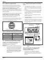
3.3.5 Jandy Variable Speed Pump DIP switch
settings
Dipswitch Settings with Local Controller
Please refer to the following table for required
settings for Dip switches 3-4 when the pump is
connected to a local controller.
Local Controller DIP Switch Settings
Controller Switch 3 Switch 4
JEP-R OFF OFF
iQPUMP01 OFF OFF
SpeedSet
Dip Switch 3-4 settings are only import-
ant when connected to a Jandy automa-
tion system using SpeedSet automation
pass-through wiring connection on the
bottom of the controller.
If applicable, please see following sec-
tions.
Dip Switch Settings with Automation
Dip Switch 3-4 setting rules are not common across
all Jandy automation systems. Please reference
the following sections to understand the required
settings.
For Jandy Aqualink RS Automation System users, a
2022 mid-year update changes the method in which
pumps in this manual interact with Jandy Aqualink
RS systems. Refer to the RS manual for more
information.
Pre-2022 Aqualink RS Firmware Rev_V and Earlier
Aqualink RS systems using firmware Rev V and
earlier, manufactured prior to mid-year 2022,
support up to 4 variable-speed pumps. Each pump
is assigned an address of 1 through 4 using Dip
Switches 3-4 on the pump. Use the table below for
pump address assignment settings.
These settings are used when connected to the
RS485 connection on the pump or when connected
to the pump using a SpeedSet controller’s
automation pass-through wiring connection on the
bottom of the controller.
Local Controller DIP Switch Settings
Address Switch 3 Switch 4
Pump 1 OFF OFF
Pump 2 ON OFF
Pump 3 OFF ON
Pump 4 ON ON
2022 Aqualink RS Firmware Rev W
and Later
Aqualink RS systems using Rev W and later,
manufactured after mid-year 2022, support up
to 16 variable-speed pumps that utilize a pre-
assigned PUMP ADDRESS. Dip Switches 3-4 are
not utilized. Pumps in this manual are all assigned a
unique PUMP ADDRESS at the factory. The PUMP
ADDRESS label can be found on the pump motor in
the location shown below.
PUMP ADDRESS
PUMP ADDRESS
Figure 15. Pump Address Label Location
When setting up pumps using this method, the
pump address of each pump will initially appear
in the unassigned pump address section of the
iAqualink App or other automation setup device.
Utilize the App or other device to complete pump
setup.

Page 16
ENGLISH AquaLink® RS Control Systems | Hardware Installation Manual
3.3.6 Wiring the Pentair® Pump
The Pentair IntelliFlo® VF LCD control panel is
disabled when communicating with the AquaLink
system and “DISPLAY NOT ACTIVE” will be
displayed. Note that AquaLink RS will not start
communicating with the Pentair IntelliFlo VF until it
has been configured accordingly. See the AquaLink
Owner’s Manual (P/N 6593L) for more information.
Connection from the AquaLink power center PCB to
the Pentair variable speed/flow pumps is via the two-
wire cable (Pentair P/N 350122). The cable pin out is
shown in Figure 16.
In order to operate up to four (4) Pentair variable
speed pumps the motor must be addressed. Refer
to the Pentair manual for instructions.
21
3
54
67
Pin 7 (Yellow)
Pin 6 (Green)
Figure 16. Cable Connector at the Pump Side
Jandy RS485
(RED) Connector Pentair RS485 Cable
Assembly
Pin 1 (no connection)
Pin 2 Yellow Wire
Pin 3 Green Wire
Pin 4 (no connection)
3.4 Heater Connection
The heater connection section applies to all heaters
or heat pumps with thermostatic circuitry of 24 VAC
or less.
NOTE If you are connecting a heater with thermostatic
circuitry of 120 VAC or greater, do not connect to
the green, 10-pin terminal bar. Instead connect
the heater to a high voltage relay in the power
center and plug the spare relay into the electric
heater relay socket on the power center PCB.
3.4.1 Jandy Heater Connections
1. Connect two #14 gauge wires, designed for use
in hot environments, to the #1 and #2 terminals
on the green, 10-pin terminal bar.
2. Connect the other ends of the #14 gauge wires
from step 1 to the fireman’s switch terminal bar
in place of the factory installed wire loop.
3. Do not disconnect high limit or pressure
switches.
4. Turn the heater thermostat(s) to maximum
setting.
5. Turn the heater switch to the ON position. For
dual thermostat heaters turn switch to Spa
position.
Non-JXi heaters:
Heater Toggle
Switch to ON
#14 Gauge Wire
Green 10-pin Terminal Bar
Power Center PCB/Bezel
Heater Thermostat to Max.
Heating Wiring
Factory Installed Wire Loop
Jandy Heater Fireman’s
Switch Connection
Terminal 1
Terminal 2
For Hi-E2 and similar heaters
S1
S2
RESET
SERVICE
TIME OUT
FILTER PUMP
AUX 1
AUX 2
AUX 3
AUX 4
AUX 5
AUX 6
AUX 7
RS6 & RS8 ONLY
RS8 ONLY
HEATER SOLAR
POOL MODE
SPA MODE
SPA DRAIN
SPA FILL
AUTO
654321
10 987654321
4321 4321
Figure 17. Jandy Heater Connection
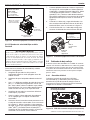
3.4.2 Guidelines for Sophisticated Diagnostic
Communication to Jandy JXi™ Heaters
1. Confirm the JXi heater software and AquaLink
RS software revisions are compatible (see tables
below).
2. Run a 4-conductor cable from the JXi heater or
the Air Energy heat pump power interface red,
4-pin connector to the power center red, 4-pin
connector (see Figure 18).
JXi Power
Interface Software
Revision
AquaLink RS Software
Revision
Any N or Later

Page 17
AquaLink® RS Control Systems | Hardware Installation Manual ENGLISH
NOTE If connecting more than two (2) items to the power
center red, 4-pin connector, a multiplex PCB (P/N
6584) is required.
RESET
SERVICE
TIME OUT
FILTER PUMP
AUX 1
AUX 2
AUX 3
AUX 4
AUX 5
AUX 6
AUX 7
RS6 & RS8 ONLY
RS8 ONLY
HEATER SOLAR
POOL MODE
SPA MODE
SPA DRAIN
SPA FILL
AUTO
654321
10 987654321
4321 4321
To Sensors, etc.
(green terminal bar)
To Remote
(brown terminal bar)
To Controller
(red terminal bar)
GR Y BK R
4 3 2 1
Power Center
JXi Control
4-Conductor
Wire
Figure 18. Jandy JXi Heater Connection to Power
Center
3.4.3 Other Brands Heater and Pump
Connections
To set up heater connections on heaters and heat
pumps made by other manufactures, please refer to
the Installation Manual provided with these heaters
and heat pumps.
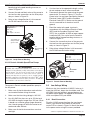
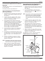
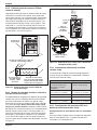
3.4.4 Guidelines for a Gas Heater and a Heat
Pump/Chiller Installation
NOTE The following steps provide the procedure for
installing a Jandy JRT Series Heat Pump and
controlling it with the solar pump relay. If your
Jandy JRT Series Heat Pump is equipped with
an RS485 Interface then you do not need to use
the solar pump relay to control it. You can control
the heat pump via the RS485 interface of the
AquaLink RS.
1. Set DIP switch S2 bit 1 to the ON position. The
AquaLink will auto-relabel solar as heat pump.
2. To run the wires from the heat pump control
panel, remove the five (5) screws that attach the
service/wiring cover panel to the heat pump.
See Figure 19.
S1
S2
RESET
SERVICE
TIME OUT
FILTER PUMP
AUX 1
AUX 2
AUX 3
AUX 4
AUX 5
AUX 6
AUX 7
RS6 & RS8 ONLY
RS8 ONLY
HEATER SOLAR
POOL MODE
SPA MODE
SPA DRAIN
SPA FILL
AUTO
654321
10 987654321
4321 4321
JANDY AquaLink RS
FILTER PUMP OFF
AIR 79°
06/26/04 MON
6:00 PM
EQUIPMENTON/OFF
ONETOUCH ON/OFF
MENU / HELP
iAquaLink
Web-Connected
Device
Note for
OneTouch:
LED will not
come on for
Heat Pump
Service/Wiring
Cover Panel
Heat Pump/
Chiller 1
Service/Wiring
Cover Panel
Standard High
Voltage Relay
To Heat
Pump #1
To Heat
Pump #2
Low Voltage Wiring
to Low Voltage
Port on Heat Pump
Heat Pump/
Chiller 2
Gas Heater
Gas Heater Connections
Terminals 1 and 2
Port for Low
Voltage Wires
J6 Connector
Figure 19. Heater and Heat Pump/Chiller Wiring

Page 18
ENGLISH AquaLink® RS Control Systems | Hardware Installation Manual
3. Run the wires from the heat pump control panel
through the wiring conduit located on the outer
right hand side of the heat pump.
4. Connect the heat pump to a standard relay, then
connect the relay to the solar pump output on
the AquaLink PCB.
5. The solar button will activate the heat pump/
chiller and the pool and/or spa heater buttons
will activate the gas heater. In this manner the
pool or spa can be heated or chilled by the heat
pump, the gas heater or both.
NOTE To program the heat pump control panel, refer to
the Heat Pump Manual.
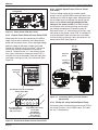
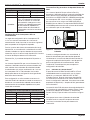
3.5 Temperature Sensors
1. Drill 3/8” hole in pipe between filter pump and
filter and install the water temperature sensor
per instructions (make certain the o-ring is in
place).
2. Install air temperature sensor outside the power
center can, not in direct sunlight and away from
motors and other heat sources.
3. Install solar temperature sensor (optional)
adjacent to solar panels.
NOTE If a solar sensor is not installed, the solar button
can be labeled and used as an extra auxiliary.
4. Run the wire to the power center, through the
low voltage raceway. Cut off excess wire. Strip
the wire jacket back 6”, then strip each wire
¼”. Connect sensor wires to the green, 10-pin
terminal bar (see Figure 20).
10 987654321
Water
Temperature
Sensor
Freeze/Air
Temperature
Sensor
Solar
Temperature
Sensor
Green 10-Pin Terminal Bar
Figure 20. Temperature Sensor Wiring for a Pool/Spa
Combination
3.6 Jandy Valve® Actuators
NOTE Mount the JVA’s according to the Jandy Valve
Actuator Installation and Operation Manual.
JVA cable is type SJW-A marked water resistant
class 3 cable and does not require conduit.
Knockouts and Heyco® fittings are provided in the
low voltage raceway.
1. Route the JVA wire to the power center.
2. Run the wire through the low voltage raceway
and plug the JVA connectors into their proper
sockets (see Section 6. Power Center Wiring
Diagram). Verify that the JVA on the suction
plumbing is connected to the Intake JVA Socket,
and the discharge plumbing is connected to the
Return JVA Socket.
NOTE Do not coil the JVA wires inside power center.
To shorten the wire, remove the JVA cover
and disconnect the wire. Shorten, strip, and
reconnect.
3. For alternate plumbing configurations the
JVA cam settings can be adjusted as needed.
See the Jandy Valve Actuator Installation and
Operation Manual, Cam Setting Chart for proper
settings.
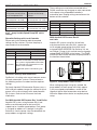
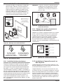
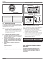
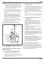
3.7 Jandy TruSense Water Chemistry
Analyzer
NOTE: Always install TruSense after the filter and before
the heating system and water care devices
(saltwater chlorinator cell, chlorinator, acid
injection...).
1. Run the RS485 cable from the TruSense Water
Chemistry analyzer to the AquaLink RS power
center.
2. Route the four conductor RS485 cable through
the low voltage raceway and connect the red
connector to the automation system. See Figure
21b.

Page 19
AquaLink® RS Control Systems | Hardware Installation Manual ENGLISH
AquaLink
RS
a
b
9.75”
(Rev Y)
Figure 21. TruSense Calibration Application
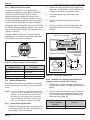
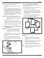
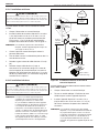
3.8 Auxiliary Power Centers
AquaLink RS All button models support one (1)
auxiliary power center.
AquaLink RS models support a maximum of three (3)
auxiliary power centers.
1. The auxiliary power centers may be wired “in
series”, starting from the primary power center
(solid line) or wired “in parallel” from the primary
power center (dashed line). See Figure 22.
2. Run four conductor, 22 AWG or larger cable
between the red, 4-pin ter mi nal bars in each
power center.
Primary
Power Center
or
PureLink
Figure 22. Wiring Multiple Power Centers
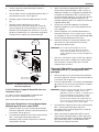
NOTE
• All temperature sensors, heater connections and
the main fi lter pump must be wired to the primary
power center.
• Never put more than two (2) wires into each of the
pins of the red, 4-pin terminal bar (use a Jandy®
multiplex board).
• If more than one auxiliary power center is installed,
set the jumpers as shown in Figure 23.
NOTE In the 2nd, 3rd, or 4th power centers, light
dimming relay must be connected to auxiliary
B5-B8, C5-C8, or D5-D8.
W1
W2
W1
W2
W1
W2
Aux PC #1
(Aux B1 to B8
for RS12, 16,
2/10, 2/14)
Aux PC #2
(Aux C1 to C8
for RS24, 2/22)
Aux PC #3
(Aux D1 to D8
for RS32, 2/30)
(No Jumpers on the Primary Power Center PCB)
Figure 23. Setting Jumpers for Multiple Auxiliary
Power Centers
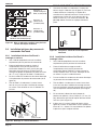
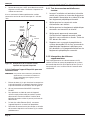
3.9 OneTouch Control Panel Indoor
Installation
3.9.1 Surface Mount OneTouch Indoor
Installation
1. With the aid of the homeowner, fi nd the best
location for the control panel.
2. Place surface mount box in the location chosen
for the control panel. Mark the holes for drilling.
Drill 3/16” holes for the sheet rock anchors and
a 1¼” hole for the 4-conductor cable.
3. Run the 4-conductor cable from the power
center to the location of the control panel (see
Figure 24).
4. Pull the 4-conductor cable through the hole in
the wall and the hole in the surface mount box.
Mount the box to the wall using the screws
pro vid ed.

Page 20
ENGLISH AquaLink® RS Control Systems | Hardware Installation Manual
Sheetrock
Surface
Mount Box
OneTouch
PCB
Faceplate
Figure 24. OneTouch™ Surface Mount Installation
5. Wire the 4-conductor cable to the red, 4-pin
terminal bar (see Figure 25). Push the 4-pin
terminal bar onto the back of the OneTouch
PCB. Place the PCB with LCD and buttons back
into the box. Insert the screws and hand tighten.
Do not overtighten. Snap the faceplate into
place.
W2
W1
4 3 2 1
Green
Yellow
Black
Red
Figure 25. OneTouch PCB - Back View
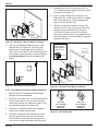
3.9.2 Flush Mount OneTouch Indoor Installation
1. With the aid of the homeowner, find the best
location for the control panel.
2. Place the flush mount box in the location chosen
for the control panel. Level the box and trace
around the outside of the box with a pencil. Cut
the hole being careful not to oversize.
3. Route the 4-conductor cable from the power
center to the indoor control panel.
4. Pull the 4-conductor cable through the hole in
the wall and the hole in the flush mount box.
Push the flush mount box into the hole in the
wall with the correct orientation (see Figure 26).
5. Depending on what size sheet rock (5/8” or
1/2”), determine which side of the cleat is to be
facing you (see Figure 27).
6. Insert a screw through the screw boss (see
Figure 26). Put a cleat into the top “U” shaped
hole. Hand tighten the screw and repeat the
process for the bottom cleat.
7. Wire the 4-conductor cable to the red, 4-pin
terminal bar. Push the 4-pin terminal bar onto
the back of the OneTouch PCB. Place the
OneTouch PCB back into the Flush Mount
Housing. Insert the screws with rubber washers
and hand tighten. Do not overtighten. Snap the
faceplate into place.
Slide cleat into the
slot opening, thread
screw through the boss
and into the cleat.
Boss
Sheet Rock
(1/2” or 5/8”
with a 4”
square cutout)
Flush
Mount
Housing
OneTouch
PCB
Faceplate
Figure 26. OneTouch Flush Mount Installation
This side
faces towards
you for 5/8”
sheetrock.
This side
faces towards
you for 1/2”
sheetrock.
Figure 27. Cleat Orientation
La page est en cours de chargement...
La page est en cours de chargement...
La page est en cours de chargement...
La page est en cours de chargement...
La page est en cours de chargement...
La page est en cours de chargement...
La page est en cours de chargement...
La page est en cours de chargement...
La page est en cours de chargement...
La page est en cours de chargement...
La page est en cours de chargement...
La page est en cours de chargement...
La page est en cours de chargement...
La page est en cours de chargement...
La page est en cours de chargement...
La page est en cours de chargement...
La page est en cours de chargement...
La page est en cours de chargement...
La page est en cours de chargement...
La page est en cours de chargement...
La page est en cours de chargement...
La page est en cours de chargement...
La page est en cours de chargement...
La page est en cours de chargement...
La page est en cours de chargement...
La page est en cours de chargement...
La page est en cours de chargement...
La page est en cours de chargement...
La page est en cours de chargement...
La page est en cours de chargement...
La page est en cours de chargement...
La page est en cours de chargement...
La page est en cours de chargement...
La page est en cours de chargement...
La page est en cours de chargement...
La page est en cours de chargement...
La page est en cours de chargement...
La page est en cours de chargement...
La page est en cours de chargement...
La page est en cours de chargement...
La page est en cours de chargement...
La page est en cours de chargement...
La page est en cours de chargement...
La page est en cours de chargement...
La page est en cours de chargement...
La page est en cours de chargement...
La page est en cours de chargement...
La page est en cours de chargement...
La page est en cours de chargement...
La page est en cours de chargement...
La page est en cours de chargement...
La page est en cours de chargement...
La page est en cours de chargement...
La page est en cours de chargement...
La page est en cours de chargement...
La page est en cours de chargement...
La page est en cours de chargement...
La page est en cours de chargement...
La page est en cours de chargement...
La page est en cours de chargement...
La page est en cours de chargement...
La page est en cours de chargement...
La page est en cours de chargement...
La page est en cours de chargement...
La page est en cours de chargement...
La page est en cours de chargement...
La page est en cours de chargement...
La page est en cours de chargement...
La page est en cours de chargement...
La page est en cours de chargement...
La page est en cours de chargement...
La page est en cours de chargement...
La page est en cours de chargement...
La page est en cours de chargement...
La page est en cours de chargement...
La page est en cours de chargement...
La page est en cours de chargement...
La page est en cours de chargement...
La page est en cours de chargement...
La page est en cours de chargement...
-
 1
1
-
 2
2
-
 3
3
-
 4
4
-
 5
5
-
 6
6
-
 7
7
-
 8
8
-
 9
9
-
 10
10
-
 11
11
-
 12
12
-
 13
13
-
 14
14
-
 15
15
-
 16
16
-
 17
17
-
 18
18
-
 19
19
-
 20
20
-
 21
21
-
 22
22
-
 23
23
-
 24
24
-
 25
25
-
 26
26
-
 27
27
-
 28
28
-
 29
29
-
 30
30
-
 31
31
-
 32
32
-
 33
33
-
 34
34
-
 35
35
-
 36
36
-
 37
37
-
 38
38
-
 39
39
-
 40
40
-
 41
41
-
 42
42
-
 43
43
-
 44
44
-
 45
45
-
 46
46
-
 47
47
-
 48
48
-
 49
49
-
 50
50
-
 51
51
-
 52
52
-
 53
53
-
 54
54
-
 55
55
-
 56
56
-
 57
57
-
 58
58
-
 59
59
-
 60
60
-
 61
61
-
 62
62
-
 63
63
-
 64
64
-
 65
65
-
 66
66
-
 67
67
-
 68
68
-
 69
69
-
 70
70
-
 71
71
-
 72
72
-
 73
73
-
 74
74
-
 75
75
-
 76
76
-
 77
77
-
 78
78
-
 79
79
-
 80
80
-
 81
81
-
 82
82
-
 83
83
-
 84
84
-
 85
85
-
 86
86
-
 87
87
-
 88
88
-
 89
89
-
 90
90
-
 91
91
-
 92
92
-
 93
93
-
 94
94
-
 95
95
-
 96
96
-
 97
97
-
 98
98
-
 99
99
-
 100
100


Jandy AquaLink RS Control Systems Manuel utilisateur
- Taper
- Manuel utilisateur
dans d''autres langues
Documents connexes
-
Jandy 400120 Manuel utilisateur
-
Jandy H0596700_B Manuel utilisateur
-
Jandy iAquaLink 3.0 Mode d'emploi
-
-
Jandy LXI Mode d'emploi
-
Jandy WaterColors RGBW LED Lights Manuel utilisateur
-
-
Jandy JVA 2444 Guide d'installation
-
Jandy JEP-R Manuel utilisateur
-
Autres documents
-
Polaris H0770000 Le manuel du propriétaire
-
 iAquaLink IQ30 Mode d'emploi
-
Zodiac JEP-R Mode d'emploi
-
Pentair Pool Color Sync Controller Guide d'installation
-
Pentair 618031 Mode d'emploi
-
Pentair Color Sync Controller Color LED Pool Lights Guide d'installation
-
-
-
BLACK DECKER BD-137 Manuel utilisateur
-
Intermatic PE24VA Guide d'installation
