Jandy WaterColors RGBW LED Lights Manuel utilisateur
- Catégorie
- Accessoires de piscine hors terre
- Taper
- Manuel utilisateur

H0596700_REVD
WARNING
FOR YOUR SAFETY - This product must be installed and serviced by a contractor who is licensed and
qualified in pool equipment by the jurisdiction in which the product will be installed where such state or
local requirements exist. The maintainer must be a professional with sufficient experience in pool equipment
installation and maintenance so that all of the instructions in this manual can be followed exactly. Before
installing this product, read and follow all warning notices and instructions that accompany this product.
Failure to follow warning notices and instructions may result in property damage, personal injury, or death.
Improper installation and/or operation may void the warranty.
Improper installation and/or operation can create unwanted electrical hazard which can
cause serious injury, property damage, or death. DO NOT MODIFY THIS EQUIPMENT
ATTENTION INSTALLER - This manual contains important information about the installation,
operation and safe use of this product. This information should be given to the owner/
operator of this equipment.
WaterColors RGBW LED Lights
Underwater Large and Small Light
INSTALLATION AND
OPERATION MANUAL
ENGLISH | FRANÇAIS | ESPAÑOL

Page 2 ENGLISH Jandy® WaterColors RGBW LED Lights | Installation & Operation Manual
Table of Contents
Section 1. Safety Information ................................ 3
Section 2. Product Description and Model
Numbers ................................................ 4
Section 3. Installing Jandy Light Fixture
During New Construction .................... 5
3.1 Preparing the Light Fixture for Installation .......... 5
3.2 Installing the Light Fixture ................................. 6
Section 4. Replacing Jandy Light Fixture
in an Existing Pool or Spa ................... 6
4.1 Preparing the Light Fixture for Replacement ...... 6
4.2 Replacing the Light Fixture ................................ 7
Section 5. Wiring Options for Controlling
Jandy WaterColors LED Lights ........... 8
5.1 Wiring to an AquaLink® RS Control System ....... 8
5.2 Wiring to a Time Clock ....................................... 8
5.3 Wiring to a Switch ............................................... 8
Section 6. Jandy WaterColors RGBW LED
Light Operating Instructions ............... 8
6.1 To Operate the Light and Change Colors ........... 8
6.2 To Reset to the Beginning of the
Color Sequence ................................................ 10
Section 7. Replacing LED Board and
Driver (PCB) ........................................ 10
7.1 Pool Clamp Removal. ....................................... 10
7.2 12V Small Light Driver (PCB) Replacement ..... 10
7.3 120V Small LED Board Replacement ...............11
7.4 120V Small Light Driver (PCB) Replacement .... 11
7.5 Large Light Driver (PCB) Replacement
(120V and 12V) .................................................11
7.6 Reassemble the Fixture. ..................................11
7.7 Reinstall the Jandy Light Into Niche Fixture. .... 13
Section 8. Twelve (12) Volt Installation ............... 13
Section 9. Exploded View and
Replacement Parts ............................. 14
9.1 Jandy Large WaterColors RGBW LED Light .... 14
9.2 Jandy Small WaterColors RGBW LED Light .... 15
FCC Regulatory Compliance Statement
This device complies with part 15 of the FCC Rules. Operation is subject to the following two conditions:
(1) This device may not cause harmful interference, and
(2) this device must accept any interference received, including interference that may cause undesired operation.
CAUTION: Changes or modications not expressly approved by the party responsible for compliance may void the
user’s authority to operate the equipment.
NOTE: This equipment has been tested and found to comply with the limits for a Class B digital device, pursuant to
part 15 of the FCC Rules. These limits are designed to provide reasonable protection against harmful interference
in a residential installation. This equipment generates, uses and can radiate radio frequency energy and, if not
installed and used in accordance with the instructions, may cause harmful interference to radio communications.
However, there is no guarantee that interference will not occur in a particular installation. If this equipment does
cause harmful interference to radio or television reception, which can be determined by turning the equipment o
and on, the user is encouraged to try to correct the interference by one or more of the following measures:
• Reorient or relocate the receiving antenna.
• Increase the separation between the equipment and receiver.
• Connect the equipment into an outlet on a circuit dierent from that to which the receiver is connected.
• Consult the dealer or an experienced radio/TV technician for help.

Page 3
ENGLISH
Jandy® WaterColors RGBW LED Lights | Installation & Operation Manual
Section 1. Safety Information
IMPORTANT SAFETY INSTRUCTIONS PERTAINING TO A RISK OF FIRE,
ELECTRIC SHOCK, OR INJURY TO PERSONS
READ AND FOLLOW ALL INSTRUCTIONS
When installing and using this electrical equipment, basic safety precautions should always be followed, including the
following:
WARNING
RISK OF ELECTRICAL SHOCK OR ELECTROCUTION. This underwater light must be installed by a
licensed or certified electrician in accordance with the National Electrical Code and applicable local codes and
ordinances. Improper installation will create an electrical hazard, which could result in death or serious injury to
pool or spa users, installers, or others due to electrical shock, and may also cause damage to property. Read
and follow the specific instructions below.
WARNING
Before installing this underwater light, read and follow all warning notices and instructions accompanying this
light. Failure to follow safety warnings and instructions can result in severe injury, death, or property damage.
Call (707) 776-8200 for additional free copies of these instructions.
CAUTION
Except when the Jandy WaterColors RGBW LED Lights are installed in an area of the swimming pool that is not
used for swimming and the lens is adequately guarded to keep any person from contacting it, the light shall be
installed in or on a wall of the pool, with the top of the lens opening not less than 18 inches (457 mm) below the
normal water level of the pool
ATTENTION INSTALLER
This manual contains important information about the installation, operation and safe use of this
product. This information should be given to the owner/operator of this equipment.
NOTICE
The Jandy WaterColors RGBW LED Lights are intended for installation in fresh water and salt water swimming
pools. It is important to ensure that the wet niches in which the lights are installed are intended for their
appropriate application, either fresh water or salt water pools.
SAVE THESE INSTRUCTIONS

Page 4 ENGLISH Jandy® WaterColors RGBW LED Lights | Installation & Operation Manual
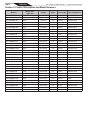
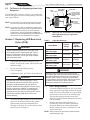
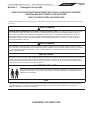
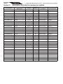
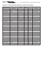
Section 2. Product Description and Model Numbers
Model # WaterColors
Light Size Voltage Amps Cord Length Face Ring Material
CPLVRGBWS30 Large 12 Volt AC 4.0 30 feet Stainless Steel
CPLVRGBWS50 Large 12 Volt AC 4.0 50 feet Stainless Steel
CPLVRGBWS100 Large 12 Volt AC 4.0 100 feet Stainless Steel
CPLVRGBWP100 Large 12 Volt AC 4.0 100 feet Plastic
CPLVRGBWS50C Large 12 Volt AC 4.0 50 feet Stainless Steel
CPLVRGBWS100C Large 12 Volt AC 4.0 100 feet Stainless Steel
CPLVRGBWP100C Large 12 Volt AC 4.0 100 feet Plastic
CPHVRGBWS30 Large 120 Volt AC 0.4 30 feet Stainless Steel
CPHVRGBWS50 Large 120 Volt AC 0.4 50 feet Stainless Steel
CPHVRGBWS100 Large 120 Volt AC 0.4 100 feet Stainless Steel
CPHVRGBWP100 Large 120 Volt AC 0.4 100 feet Plastic
CPHVRGBWS150 Large 120 Volt AC 0.4 150 feet Stainless Steel
CPHVRGBWS250 Large 120 Volt AC 0.4 250 feet Stainless Steel
CPHVRGBWS50C Large 120 Volt AC 0.4 50 feet Stainless Steel
CPHVRGBWS100C Large 120 Volt AC 0.4 100 feet Stainless Steel
CPHVRGBWP100C Large 120 Volt AC 0.4 100 feet Plastic
CSLVRGBWS30 Small 12 Volt AC 2.0 30 feet Stainless Steel
CSLVRGBWS50 Small 12 Volt AC 2.0 50 feet Stainless Steel
CSLVRGBWS100 Small 12 Volt AC 2.0 100 feet Stainless Steel
CSLVRGBWP100 Small 12 Volt AC 2.0 100 feet Plastic
CSLVRGBWS50C Small 12 Volt AC 2.0 50 feet Stainless Steel
CSLVRGBWS100C Small 12 Volt AC 2.0 100 feet Stainless Steel
CSLVRGBWP100C Small 12 Volt AC 2.0 100 feet Plastic
CSHVRGBWS30 Small 120 Volt AC 0.2 30 feet Stainless Steel
CSHVRGBWS50 Small 120 Volt AC 0.2 50 feet Stainless Steel
CSHVRGBWS100 Small 120 Volt AC 0.2 100 feet Stainless Steel
CSHVRGBWP100 Small 120 Volt AC 0.2 100 feet Plastic
CSHVRGBWS150 Small 120 Volt AC 0.2 150 feet Stainless Steel
CSHVRGBWS250 Small 120 Volt AC 0.2 250 feet Stainless Steel
CSHVRGBWS50C Small 120 Volt AC 0.2 50 feet Stainless Steel
CSHVRGBWS100C Small 120 Volt AC 0.2 100 feet Stainless Steel
CSHVRGBWP100C Small 120 Volt AC 0.2 100 feet Plastic

Page 5
ENGLISH
Jandy® WaterColors RGBW LED Lights | Installation & Operation Manual
Section 3. Installing Jandy Light
During New Construction
WARNING
Risk of Electrical Shock or Electrocution.
This underwater light must be installed by a
licensed or certied electrician or a qualied
pool serviceman in accordance with the National
Electrical Code and all applicable local codes and
ordinances. Improper installation will create an
electrical hazard, which could result in death or
serious injury to pool or spa users, installers or
others due to electrical shock, and may also cause
damage to property.
Always disconnect the power to the color light at
the circuit breaker before installing or servicing
the light. Failure to do so could result in death or
serious injury to serviceman, pool or spa users or
others due to electrical shock.
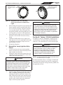
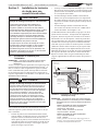
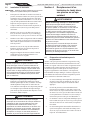
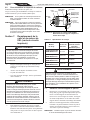
3.1 Preparing the Light Fixture for
Installation
NOTE: The electrician must complete preparatory steps
before light fixture is installed. See Figure 1.
Ensure that the pool meets the requirements of the
current National Electrical Code
®
and all local codes and
ordinances. A licensed or certied electrician must install
the electrical system to meet or exceed those requirements
before the underwater light is installed.
WARNING
Risk of Electrical Shock or Electrocution
which could result in serious injury or death. A
Ground Fault Circuit Interrupter (GFCI) for 120
Volt transformers should be used if required by
the transformer manufacturer or if required by
the local applicable code and/or Authority Having
Jurisdiction (AHJ). When a GFCI is used, the
conductors on the load side of the GFCI circuit
shall not occupy conduit boxes, or enclosures
containing other conductors unless the additional
conductors are also protected by a GFCI. Refer to
local codes for complete details.
Some of the requirements of the National Electrical
Code, which the pool or spa’s electrical systems must
meet, are as follows:
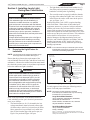
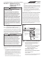
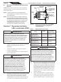
• The Junction Box (or, for 12 volt models, the low
voltage transformer) must be located at least eight
(8) inches above water level, at least four (4) inches
above ground level or pool deck level, and at least
four (4) feet from the edge of the pool or spa; see
Figure 1 for pools and Figure 2 for spas.
• The light xture and all metal items within ve (5)
feet of the pool or spa must be properly electrically
bonded to a reliable point of grounding.
• The wet niche must be properly installed so that the
top edge of the underwater light’s lens is at least 18
inches below the surface of the water in the pool or
spa; see Figure 1 or 2.
National Electrical Code® (NEC®) requires bonding
of the Pool Water. Where none of the bonded pool
equipment, structures, or parts are in direct connection
with the pool water; the pool water shall be in direct
contact with an approved corrosion-resistant conductive
surface that exposes not less than 5800 mm² (9 in²) of the
surface area to the pool water at all times. The conductive
surface shall be located where it is not exposed to
physical damage or dislodgement during usual pool
activities, and it shall be bonded in accordance with the
bonding requirements of NEC Article 680. Refer to
locally enforced codes for any additional pool and spa
bonding requirements.
NOTE: To be certain that the pool’s electrical system meets
all applicable requirements, the electrician should also
consult the local building department.
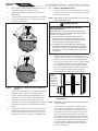
4" min.
48"
min.
8" min. Junction Box or Low
Voltage Transformer, to the
max water level of the pool.
18" min. to top of Lens.
11.50"
Concrete must be cut
back around Niche to
allow for a compacted
plaster seal.
Coil 4 ft. of light cable
around Fixture.
#8 AWG Ground
Connector bonding
is located at rear
of niche.
Rigid
Conduit
To GFCI, Circuit
Breaker and
Power Source.
16”
Figure 1. Jandy Digital Color Light Installation
Use only approved wet niches (see following note) to
ensure a safe and proper installation.
NOTE: Jandy lights are ETL listed (ETL report/file
3141154CHI) for installation with only the following
manufacturer’s wet niche fixtures:
Large Niche Model Numbers:
Jandy: PLNICLRG, PLNICVFLRG, WT000002,
SSNICLRG1R, SSNICLRG1S
Pentair: 620004, 78210200 thru 700, 78210401
Hayward DuraNiche: SP0600U
Small Niche Model Numbers:
Jandy: PLNICSM, SSNICSM
Pentair: 79206600
PentairPentair®® and Sta-Rite and Sta-Rite®® are registered trademarks of Pentair, Inc. are registered trademarks of Pentair, Inc.
HaywardHayward®® is a registered trademark and DuraNiche is a registered trademark and DuraNiche™™ is a trademark is a trademark
of Hayward Pool Products, Inc.of Hayward Pool Products, Inc.

Page 6 ENGLISH Jandy® WaterColors RGBW LED Lights | Installation & Operation Manual
3.2 Installing the Light Fixture
NOTE: Perform these steps only after the electrical system
requirements are met.
1. Feed cord through conduit to junction box,
leaving at least four (4) feet of cord at the light
xture to coil into the base of the light niche, see
Figure 1. The four (4) feet of cord allows the light
to be serviced after the pool is lled with water.
2. Cut the cord at the junction box, leaving at least
six (6) inches of cord to make connections.
3. Strip six (6) inches of the outer cord jacket to
expose the three insulated wires.
Be careful not to
damage the insulation on the three (3) inner wires.
4. Install strain relief over cord jacket and connect
all three (3) wires to the corresponding circuit
wires in the junction box. Install the junction box
cover.
5. Coil the 4-foot length of cord around the xture
or into the base of the pool niche, and place the
light assembly into the niche.
6. Engage the retainer tab on the bottom of the face
ring, then pivot the top of the xture inward and
tighten the special pilot screw.
WARNING
Use only the special pilot screw provided with this
underwater light. This screw mounts and electrically
grounds the housing securely to the mounting ring
and wet niche. Failure to use the screw provided
could create an electrical hazard, which could result
in death or serious injury to pool or spa users,
installers or others due to electrical shock.
7. Fill the pool until the underwater light is
completely submerged in water before operating
the light for more than 2 minutes. The light will
heat up quickly when operated outside of water.
Turn on main switch or circuit breaker, and the
switch, which operates the underwater light, to
check for proper operation. Refer to Section 6,
Operating Instructions.
WARNING
Never operate this underwater light for more than
10 seconds unless it is totally submerged in water.
Without total submersion, the light assembly will get
extremely hot, which may result in serious burns
or in breakage of the bulb or lens. This may result
in serious injury to pool or spa users, installers, or
bystanders or damage to property.
Section 4. Replacing Jandy Light
Fixture in an Existing Pool
or Spa
WARNING
Risk of Electrical Shock or Electrocution.
This underwater light must be installed by a
licensed or certied electrician or a qualied
pool serviceman in accordance with the National
Electrical Code and all applicable local codes and
ordinances. Improper installation will create an
electrical hazard, which could result in death or
serious injury to pool or spa users, installers or
others due to electrical shock, and may also cause
damage to property.
Always disconnect the power to the color light at
the circuit breaker before installing or servicing
the light. Failure to do so could result in death or
serious injury to serviceman, pool or spa users or
others due to electrical shock.
4.1 Preparing the Light Fixture for
Replacement
Verify that the pool meets the requirements of the current
National Electrical Code® (NEC) and all local codes
and ordinances. A licensed or certied electrician must
install the electrical system to meet or exceed those
requirements before the underwater light is installed.
Some of the requirements of the National Electrical
Code, which the pool’s electrical system must meet, are
as follows:
1. The lighting circuit must have a Ground Fault
Circuit Interrupter (GFCI) for 120 volt models,
and must have an appropriately rated circuit
breaker.
2. The junction box (or, for 12 volt models, the low
voltage transformer) must be located at least eight
(8) inches above water level, at least four (4)
inches above ground level or pool deck level, and
at least 48 inches from the edge of the pool or spa.
See Figure 1.
3. The light xture and all metal items within ve
(5) feet of the pool must be properly electrically
bonded to a reliable point of grounding.
4. The wet niche must be properly installed so that
the top edge of the underwater light’s lens is at
least 18 inches below the surface of the water in
the pool. See Figure 1.

Page 7
ENGLISH
Jandy® WaterColors RGBW LED Lights | Installation & Operation Manual
5. The wet niche must be properly electrically
bonded and grounded via the No. 8 AWG ground
connector located at the rear of the niche. See
Figure 1.
To be certain that the pool’s electrical system meets
all applicable requirements, the electrician should also
consult the local building department.
4.2 Replacing the Light Fixture
NOTE: Perform these steps only after the electrical system
requirements are met.
WARNING
Failure to bring the pool’s electrical system up to
code requirements before installing the underwater
light will create an electrical hazard which could
result in death or serious injury to pool or spa
users, installers, or others due to electrical shock,
and may also cause damage to property.
NOTE: The light fixture may be replaced without removing
water from the pool.
1. Turn o the main electrical switch or circuit
breaker, as well as the switch, which operates the
underwater light.
2. Unscrew the special pilot screw at top of the
face ring and remove the light assembly from the
niche, and place the assembly on the deck.
WARNING
Be sure to keep the special pilot screw provided
with this underwater light. This screw mounts and
electrically grounds the housing securely to the
mounting ring and wet niche. Failure to use the
screw provided could create an electrical hazard,
which could result in death or serious injury to pool or
spa users, installers or others due to electrical shock.
3. Remove Junction Box cover, disconnect the light
xture wires and strain relief, and then pull the
cord out of the conduit from the niche.
4. Feed the new light xture cord through the
conduit from the niche to the Junction Box.
NOTE: Depending on the length of the conduit, special tools
may be required to pull the cord through the conduit.
5. Leave at least four (4) feet of cord to coil around
the light xture or coiled into the base of the light
niche, see Figure 1. This allows the light to be
serviced after the pool is lled with water.
6. Cut the cord at the Junction Box, leaving at least
six (6) inches of cord to make connections.
7. Strip six (6) inches of the outer cord jacket from
the cord to expose the three insulated wires. Be
careful not to damage the insulation on the three
(3) inner wires.
8. Install the strain relief over the cord jacket and
connect all three wires to the corresponding
circuit wires in the junction box. Install the
junction box cover.
9. Reinstall the light assembly into the niche and
tighten the special pilot screw.
WARNING
Use only the special pilot screw provided with this
underwater light. This screw mounts and electrically
grounds the housing securely to the mounting ring
and wet niche. Failure to use the screw provided
could create an electrical hazard, which could result
in death or serious injury to pool or spa users,
installers or others due to electrical shock.
10. Fill the pool until the underwater light is
completely submerged in water before operating
the light for more than 10 seconds. Turn on main
switch or circuit breaker, as well as the switch,
which operates the underwater light, to check for
proper operation. Refer to Section 6, Operating
Instructions.
WARNING
Never operate this underwater light for more than
10 seconds unless it is totally submerged in water.
Without total submersion, the light assembly will get
extremely hot, which may result in serious burns
or in breakage of the bulb or lens. This may result
in serious injury to pool or spa users, installers, or
bystanders or in damage to property.

Page 8 ENGLISH Jandy® WaterColors RGBW LED Lights | Installation & Operation Manual
Section 5. Wiring Options for
Controlling Jandy
WaterColors LED Lights
NOTE: The Jandy WaterColors RGBW LED Lights will not
operate properly with light dimmers. Do not wire the
Jandy Lights to any dimming circuitry.
To the extent allowed by code and capacity of the
electrical equipment, multiple Jandy lights may be
controlled with a single switch so their colors will always
be synchronized.
Separate switches may be used to control the on/o and
color functions of each Jandy light. It is recommended
that these switches be located next to each other to
facilitate simple color synchronization when desired.
All switches must be operated at the same time to assure
color synchronization. Otherwise, the lights will work
independently of each other.
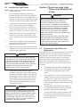
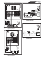
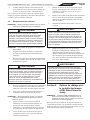
5.1 Wiring to an AquaLink® RS
Control System
The Jandy WaterColors RGBW LED Lights can be wired
into the Jandy AquaLink® RS control system to provide
simplied operation of the lights, as well as a means to
synchronize the color change function. Connect the lights
to one of the auxiliary relays in the Power Center.
NOTE: It is recommended to connect one light per relay so
each light can be controlled separately. However, up to
four lights can be connected on a single relay. If there
are more than four lights installed on one AquaLink RS
system, ensure there is more than one auxiliary relay
available in the Power Center.
Refer to Figures 2 and 3 to connect the Jandy Color
Lights to the Power Center.
WARNING
RISK OF ELECTRICAL SHOCK OR
ELECTROCUTION, which could result in serious
injury or death. A Ground Fault Circuit Interrupter
(GFCI) must be provided for 120 volt models. A
Ground Fault Circuit Interrupter (GFCI) for 120
Volt transformers should be used if required by the
transformer manufacturer or if required by the local
applicable code and/or Authority Having Jurisdiction
(AHJ). When a GFCI is used, the conductors on
the load side of the GFCI circuit shall not occupy
conduit, boxes, or enclosures containing other
conductors unless the additional conductors are
also protected by a GFCI. Refer to local codes for
complete details.
NOTE: The Jandy WaterColors Lights are available in 120-
volt and 12-volt versions. If installing a 12-volt light,
a NRTL certified 120-volt/12-volt step-down (AC)
transformer must be used. For more information about
12-volt installations, refer to Section 8 of this manual.
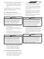
5.2 Wiring to a Time Clock
The Jandy WaterColors RGBW LED Lights can be wired
into a basic time clock to automatically turn on the lights
at a predesignated time. Refer to Figure 4 to connect the
lights into the time clock.
5.3 Wiring to a Switch
The Jandy WaterColors RGBW LED Lights can be wired
into a switch to manually turn on/o the lights. Refer to
Figure 5 to connect the lights into the switch.
Section 6. Jandy WaterColors RGBW
LED Light Operating
Instructions
6.1 To Operate the Light and Change
Colors
Turn the light ON. The rst time the light is turned on,
the color sequence begins with the Alpine White. To
change the color, turn the light OFF and then ON within
three (3) seconds. Continue turning OFF and ON until
the desired light color mode is reached. See Table 1 for
the color mode sequence.
Table 1. Jandy WaterColors Lights Sequence
Sequence Order Color Modes
1 Alpine White
2 Sky Blue
3 Cobalt Blue
4 Caribbean Blue
5 Spring Green
6 Emerald Green
7 Emerald Rose
8 Magenta
9 Violet
10 Slow Color Splash
11 Fast Color Splash
12 America the Beautiful
13 Fat Tuesday
14 Disco Tech
NOTE: When the light is turned OFF for more than seven (7)
seconds, it will remain in the color set that is currently
active. When the light is turned back ON, the light will
be on the same color set.

Page 9
ENGLISH
Jandy® WaterColors RGBW LED Lights | Installation & Operation Manual
GFCI
Black
White
Green
Ground
Ground
Neutral
120 VAC
Power Supply
Black
White
Green
JUNCTION
BOX
120V
LED
Light
Figure 2. 120-Volt Jandy WaterColors RGBW LED
Light Wiring Diagram
Black
White
Green
Ground
Neutral
120 VAC
Power Supply
Black
White
Green
JUNCTION
BOX
12V
LED
Light
120V/12V
Transformer
Black
White
Green
Figure 3. 12-Volt Jandy WaterColors RGBW LED
Light Wiring Diagram
Clock
Motor
Ground
Ground
Neutral
Line
A12
GFCI
Black
White
Green
Black
White
Green
JUNCTION
BOX
120V
LED
Light
120 V
SUPPLY
Figure 4. Wiring the Jandy WaterColors RGBW LED
Light to a Time Clock
Ground
Ground
Neutral
Line
120 V
Supply
GFCI
Black
White
Green
JUNCTION
BOX
Black
White
SWITCH
Black
White
Green
120V
LED
Light
Figure 5. Wiring the Jandy WaterColors RGBW LED
Light to a Switch

Page 10 ENGLISH Jandy® WaterColors RGBW LED Lights | Installation & Operation Manual
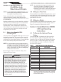
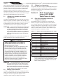
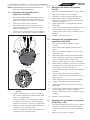
1
POOL WALL
Power
Cord Niche
POOL LIGHT
ASSEMBLY
PILOT SCREW
Push up on
bottom of
light assembly
2
Power
Cord Niche
SPA LIGHT
ASSEMBLY SPA WALL
1
PILOT SCREW
Push up on
bottom of
light assembly
2
Unscrew pilot screw
and pull top of light
assembly away from
spa wall
Bonding
cable
Unscrew pilot screw
and pull top of light
assembly away from
pool wall
Bonding
cable
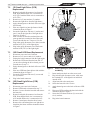
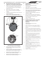
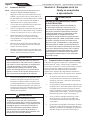
Figure 6. Removing the Jandy WaterColors RGBW
LED Light Assembly for Light Driver
Replacement
Table 2. Light Specications
Jandy Model Fixture
Voltage
Light Driver
(PCB)
Part Number
WaterColors RGBW
LED Large Light 12 Volt AC R0739500
WaterColors RGBW
LED Large Light 120 Volt AC R0739400
WaterColors RGBW
LED Small Light 12 Volt AC R0785700
WaterColors RGBW
LED Small Light 120 Volt AC R0739600
WARNING
Be sure to keep the special pilot screw from this
underwater light. This screw mounts and electrically
grounds the housing securely to the mounting ring
and wet niche. Failure to use the screw provided
could create an electrical hazard, which could result
in death or serious injury to pool or spa users,
installers or others due to electrical shock.
7.1 Pool Clamp Removal.
1. Loosen the Phillips head screws (six (6) for small
light, eight (8) for large light) to allow the bottom
clamp to be removed from the face ring assembly.
Do not remove the screws or the retaining rings.
The retaining rings prevent the screws from
falling free from the bottom clamp and also aid in
ease of assembly.
2 Remove the bottom clamp, the face ring
assembly, the glass lens, and the gasket from
the xture. Remove the silicone gasket from
the lens. Refer to Section 9, Exploded View and
Replacement Parts.
NOTE: Always install a new lens silicone gasket whenever
disassembling the light.
6.2 To Reset to the Beginning of the Color
Sequence
Turn the light OFF, wait four (4) to ve (5) seconds, then
turn ON, the light will return to the beginning of the color
cycle (Alpine White).
NOTE: If an AquaLink® RS control system is being used the
color set can be selected using the indoor controller.
NOTE: To synchronize colors on multiple Jandy WaterColors
RGBW LED Light systems wired to separate switches,
perform the above actions on all of their switches
simultaneously. All Jandy WaterColors RGBW LED
Lights will synchronize automatically if activated by the
same switch. No other accessories are required.
Section 7. Replacing LED Board and
Driver (PCB)
WARNING
Always disconnect power to the color light at the
circuit breaker before servicing the light. Failure
to do so could result in death or serious injury to
installer, serviceman, pool or spa users or others
due to electrical shock.
1. Turn o the main electrical switch or circuit
breaker, as well as the switch, which operates the
underwater light.
2. Be sure to have the following items:
• A new lens gasket.
• A light driver board. See Table 2 for specication.
WARNING
Replace light driver with the same type. Failure
to replace the light driver with the same type will
damage the light assembly and may cause an
electrical hazard resulting in death or serious injury
to pool or spa users, installers, or others due to
electrical shock, and may also cause damage to
property. Be sure the power is switched OFF before
removing or installing PCB. Allow PCB to cool
before replacing.
3. To remove the light assembly, unscrew the special
pilot screw at the top of the face ring, remove
light assembly from niche and gently place
assembly on the deck. It is not necessary to drain
down the pool. See Figure 6.

Page 11
ENGLISH
Jandy® WaterColors RGBW LED Lights | Installation & Operation Manual
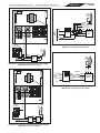
7.2 12V Small Light Driver (PCB)
Replacement
1. Remove both quick disconnect wires from the
PCB. Note that the black wire is connected to
ACN (TP-2) and the White wire is connected to
ACL (TP-1).
2. Remove two (2) nuts and two (2) washers.
3. Remove the light driver from the light xture.
4. Apply thermal grease to the back of the new light
driver board.
5. Place new light driver into the xture with the
orientation shown in Figure 7.
6. Secure the light driver with one (1) washer and
one (1) nut on the right side of the light driver.
Torque to 12 in-lbs.
7. Place a washer on the other stud and place the
green ground wire terminal on the washer and
secure both with the nut. Torque to 12 in-lbs.
8. Plug in the quick disconnect wire (white) onto the
terminal ACL (TP-1) of the light engine.
9. Plug in the quick disconnect wire (black) onto
terminal ACN (TP-2) of the light engine.
7.3 120V Small LED Board Replacement
1. Disconnect power and wait 5 minutes.
2. Remove two (2) screws and six (6) washers.
3. Unplug the board connector from the light engine.
4. Remove the LED board from the heat sink. If
you are also replacing the driver board, you can
proceed now to step 7.4
5. Apply thermal grease to the back of the new LED
board.
6. Place new LED board into the heat sink with the
orientation shown in Figure 7.
7. Secure the LED board with two (2) screws and
two (2) washers.
8. Plug in the board connector.
7.4 120V Small Light Driver (PCB)
Replacement
1. Disconnect power and wait 5 minutes.
2. Remove LED board as instructed in step 7.3
3. Remove 2 screws from the heat sink and remove
the heat sink.
4. Remove both quick disconnect wires from the
PCB. Note that the black wire is connected to
ACN and the White wire is connected to ACL.
5. Remove 2 metal posts from the driver board.
6. Remove driver board and place new light driver
board into the xture with the orientation shown
in Figure 7.
Spa Light
Driver
Black (12V) White (12V)Green
Nylon
Washer
Nut
TP-2
ACN (Black)
ACL (White)
TP-1
Secure
First
CSHVLED-L 2016-05-28
TP-2
TP-1
TP-G
TP-VO
TP-T
TP-V
GND
5V
PF
18V
J18
U1
R14
J16
F1
RS2
J12
RS3
J13
RS9
RS8
RS1
RS7
J11
RS6
Q1
Q2
Q5
Q3
Q8
Q9
U2
U3
Q6
Q7
Q10
Q4
CON2
E1
E2
WD1
WD2 WD4 WD5
WD3
D2
D1 D4
R13
R15
RT1
J15
J17
R16
J14
J09
J10
R9
R11
ZD2
RS5
J05
J06
C4
RS4
C1
J08
C3
C2
R5
J07
R6
R8
R7
J04
R4
D5
J03
R3
RN3
RN1
RN2
R0
D3
RD1
RD2 RD3 RD4 RD5
GD1
GD2 GD3 GD4
BD1 BD2 BD3
BD4
U4
RN4
R1
CH1
R2
ZD1
AC1-White
AC2-Black
Black
GND
TP-L
CSHVLED-C
TP-N
TP-G
2016-05-28
GND
5V
PF
15V
TP-FL
Q1
L1
T01
U2
CY1
C1
U1
J01
R15A
C05
EC3
EC2
R10
R16
R09
C02
R13
R15
R12
C03
R14
R11
D05
D06
R08
C04
D7
D03
D01
D04
D02
R23
R22A
R04
R25
C06
ZD2
R22
R03
F1
R24
D07
ZD1
R21
R19
R01
C01
R07
RS1
RS3
RS2
R20
R17
R02
R18
J02
R05
EC1
C0
ACL-White
ACN
CX1
RV1
R6
GD1
U3
120V Wiring Driver Board
12V Wiring LED Board
Figure 7. Small Light Engine (PCB) Replacement
and Wiring
7. Insert metal posts back on to the screw studs.
8. Plug in both quick disconnect wires, white onto
the terminal ACL of the light driver and black
onto the ACN.
9. Align heat sink to the metal posts
10. Secure the heat sink with 2 screws
11. Apply thermal grease to the back of the new LED
board.
12. Place new LED board into the heat sink with the
orientation shown in Figure 7.
13. Secure the LED board with two (2) screws and
six (6) washers.
14. Plug in the board connector.

Page 12 ENGLISH Jandy® WaterColors RGBW LED Lights | Installation & Operation Manual
7.5 Large Light Driver (PCB) Replacement
(120V and 12V)
1. Disconnect power and wait 5 minutes.
2. Unplug the quick disconnect terminals and the
grounding wire (green) from the light driver.
3. Remove three (3) nuts and washers.
4. Remove the LED board, light driver board and
board connector from the light xture.
5. Apply thermal grease to the back of the new
LED board.
6. Place new LED board and light driver board into
the xture with the orientation shown in Figure 8.
120V Wiring
WhiteGreen
Black
Nut
Secure
First
12V Wiring
White
Green
Black
TP-N TP-L
Nylon
Washer
Nut
TP-N TP-L
Secure
First
36V
PF
5V
GND
WHITE
W
B
G
RED
GREEN BLUE
GND
GND
2016-05-28
CPHVLED-L
TP-1
TP-3
TP-4
TP-5
TP-6
TP-8
TP-7
TP-9
TP-OR
TP-OB TP-2
TP-OG
J37
MOV1
C14
E2
E1
R9
C4
J19
J18
BD8 BD7
BD6
BD5
BD4
BD3
BD2
BD1
GD8
GD7
GD6
GD5
GD4
GD3
GD2
GD1
RD12
RD11
RD10
RD9
RD8
RD7RD6
RD5
RD4
RD3
RD2
RD1
J35
J32
WD2
WD9
L5
J12
D2
L4
J17
R8
J14
U6
J06
C7
J05
J09
J03
J04
J22
J27
J30
CON2
C8
D3
L3
RS3
R23
R22
C9 U7
RS4
J25
C10
D4
L2
RS5
R26
R24
C11
U8
RS6
R25
C12 D5
L1
RS7
R27 RS8
R28
J33
J31
J29
J28 J26
J24
J34
J16
C2
R2
R3
U2
R1
C1
ZD1
U1
C3
U4
U5
R15 R13
R14
R19 C5
R12 R6
R5
Q1
U3
R17
R18
J21
J08
C6
J13
R10
ZD3
ZD2
R16
D1
R11
R4
J01
WD1
WD3
WD5
WD4
WD6
WD7
WD10 WD8
RS2
R20
J20
J15
J11
J36
J07
J10
R7
Q2
R30
R31
J02
R32
E3
E4
E6
E5
RS1
MOV-1
CH1
C13 U9
GND 5V PF 36V
TP-L
CPLVLED-C 2016-06-05
TP-N
TP-V
TP-G
NC6
NC5
GD3
GD2
GD1
CH1
NC8
NC4
L1
NC7
L2
NC2
MOV1
MOV2
NC3
GD2
NC1
C0
R0
T1
R1 R2
U3
ZD1
C4
C2
C8
R7
C3
J01
R10
R16
R11
C5 C6
R15
R13
RS2
RS5
D9
RS1
RS4
RS6
RS3
CY1
CY2
U1
Q1
C7
R6
D12
R14
R12
R3
R4
RS7
RS9
RS8
R5
D1
D2
D3
D4
D11
EC2
R9
R8
D6
D8
EC1
R18
36V
PF
5V
GND
WHITE
W
B
G
RED
GREEN BLUE
GND
GND
2016-05-28
CPHVLED-L
TP-1
TP-3
TP-4
TP-5
TP-6
TP-8
TP-7
TP-9
TP-OR
TP-OB TP-2
TP-OG
J37
MOV1
C14
E2
E1
R9
C4
J19
J18
BD8 BD7
BD6
BD5
BD4
BD3
BD2
BD1
GD8
GD7
GD6
GD5
GD4
GD3
GD2
GD1
RD12
RD11
RD10
RD9
RD8
RD7RD6
RD5
RD4
RD3
RD2
RD1
J35
J32
WD2
WD9
L5
J12
D2
L4
J17
R8
J14
U6
J06
C7
J05
J09
J03
J04
J22
J27
J30
CON2
C8
D3
L3
RS3
R23
R22
C9 U7
RS4
J25
C10
D4
L2
RS5
R26
R24
C11
U8
RS6
R25
C12 D5
L1
RS7
R27 RS8
R28
J33
J31
J29
J28 J26
J24
J34
J16
C2
R2
R3
U2
R1
C1
ZD1
U1
C3
U4
U5
R15 R13
R14
R19 C5
R12 R6
R5
Q1
U3
R17
R18
J21
J08
C6
J13
R10
ZD3
ZD2
R16
D1
R11
R4
J01
WD1
WD3
WD5
WD4
WD6
WD7
WD10 WD8
RS2
R20
J20
J15
J11
J36
J07
J10
R7
Q2
R30
R31
J02
R32
E3
E4
E6
E5
RS1
MOV-1
CH1
C13 U9
TP-V
TP-G
TP-L
TP-N
ACL-White
ACN-Black
-+
2016-05-28
CPHVLED-C
GND
5V
PF
36V
GD2
C5
D5B
NC2
F1
MOV1
C2
R25
R12
C7
R20
R10
R19
J02
R9
R5
R22
R13
R4
C3
R8
C4
J06
J03
J05
R14
R15 D3
J04
R17
R11
R2
R16
R3
R18
C6R21
D2
D1
D1A D1B D1D
D1C
L1
CY1
CY3
U1
Q1
U2
R27
D5
R26
C8
CX1
J01
R23
NC1
L2
R7R6
R29
R30 U3
MOV2
C1
CY2
D4
CH1
+
-
C9
D5A
GD1
R28
MOV3
T1
AC1-White
AC2-Black
Figure 8. Large Light Engine (PCB) Replacement
and WiringLights
7. Secure the new boards with 3 washers, spilt
washers and nuts. Torque to 12 in-lbs.
8. Plug in the white quick disconnect wire onto the
terminal AC1 (TP-L) of the light driver board.
9. Plug in black quick disconnect wire onto terminal
AC2 (TP-N) of the light driver. Ensure board
connectors are connected to both boards.
10. To secure the ground wire, place the at washer,
followed by the ground wire, followed by the split
washer, securing in place with the nut. Torque to
12 in-lbs.
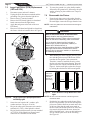
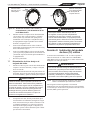
7.6 Reassemble the Fixture.
1. If not already done, remove the gasket from the
glass lens and install a new gasket on the lens. On
the small light, remove the diverger from the lens.
NOTE: A new lens gasket must be used each time the light is
reassembled.
WARNING
Risk of Electrical Shock or Electrocution.
Always install a new lens gasket whenever
disassembling the light. Failure to do so may permit
water to leak into the assembly, which could cause:
(a) An electrical hazard resulting in death or
serious injury to pool or spa users, installers, or
others due to electrical shock, or
(b) A malfunction of the Jandy WaterColors RGBW
LED Light, which likewise could result in serious
injury to pool or spa users, installers, or bystanders,
or in damage to property.
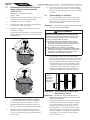
2. While holding the xture upright, place the glass
lens with the gasket on top of the xture. Please
note that the lens gasket is not symmetrical.
Therefore, it must be installed correctly so that
the lens can seal to the xture housing. Place the
gasket on the lens with the orientation shown in
Figure 9. On the small light, replace the diverger
by tucking the tabs between the lens and gasket.
Fixture Lense
Thick molded
side of the
gasket must
mate with
the body of
the housing
Figure 9. Cross Section of Jandy WaterColors LED
Light
NOTE: Be sure to face the dull side of the diverger down
towards the PCB.
3. Position the lens and gasket on the xture. Place
the face ring assembly over the lens and align the
pilot screw with the small arrow mark on the face
of the lens. Note that the small arrow mark on
the face of the lens and the pilot screw of the face
ring must be aligned with the arrow located on
xture label that reads, “Arrow on this label must
line up with the pilot screw on the Face Ring”.
See Figure 10.

Page 13
ENGLISH
Jandy® WaterColors RGBW LED Lights | Installation & Operation Manual
Align arrow of the
lens with the pilot
screw
Align pilot screw with
the arrow located on
the xture label
Figure 10. Alignment of the Lens, Face Ring,
Housing and Clamps for WaterColors
Lights
4. While holding the aligned face ring assembly and
xture together, turn the assembly upside down
and set it on the old gasket, using the old gasket
as an assembly xture. This will keep the lens
and gasket assembly from being pushed out of the
face ring while you secure it to the light xture.
5. Spread the bottom clamp over the electrical cord
and slide it onto the back of xture to the top
clamp.
6. Tighten the Phillips head screws (eight (8) for
large light and six (6) for small light) on the light
in alternating cross-pattern. Torque screws to
approximately 25 in-lbs.
7. Discard the old gasket.
7.7 Reinstall the Jandy Light Into Niche
Fixture.
1. Coil the extra four (4) feet of cord around the
xture or into the base of the niche and place the
light assembly into the niche.
2. Engage the retainer tab on the bottom of the face
ring, then pivot the top of the xture inward and
tighten the special pilot screw.
WARNING
Use only the special pilot screw provided with this
underwater light. This screw mounts and electrically
grounds the housing securely to the mounting ring
and wet niche. Failure to use the screw provided
could create an electrical hazard, which could result
in death or serious injury to pool or spa users,
installers or others due to electrical shock.
3. If pool is empty, Fill the pool until the underwater
light is completely submerged in water before
operating the light for more than 2 minutes. The
light will heat up quickly when operated outside
of water. Turn on main switch or circuit breaker,
and the switch, which operates the underwater
light, to check for proper operation.
WARNING
Never operate this underwater light for more than
10 seconds unless it is totally submerged in water.
Without total submersion, the light assembly will get
extremely hot, which may result in serious burns or
in damage to the light. This may result in serious
injury to pool or spa users, installers, or bystanders
or in damage to property.
Section 8. Twelve (12) Volt Installation
A separate 12-Volt AC Transformer is required on all
12-Volt Models. For Jandy WaterColors RGBW LED
Light use a 150-watt multi-tap 12-volt system per light.
WARNING
To minimize risk of Electrical shock or electrocution,
which could result in injury or death, for supply
connection of low-voltage lights use only an
isolating low voltage power supply, evaluated
and listed by a Nationally Recognized Testing
Laboratory (NRTL) for swimming pool use.
NOTE: For optimum performance Jandy recommends to use
one transformer per 12-volt light.
To ensure maximum safety, it is strongly recommended
that a transformer that has been listed or recognized by
a Nationally Recognized Testing Laboratory (NRTL) for
the application be used.

Page 14 ENGLISH Jandy® WaterColors RGBW LED Lights | Installation & Operation Manual
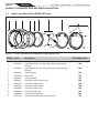
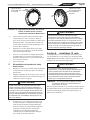
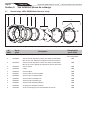
Section 9. Exploded View and Replacement Parts
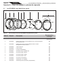
9.1 Jandy Large WaterColors RGBW LED Light
1
8
5
2
35 467 7
1
8
5
23 54 6 7
7
Figure 11. Jandy Large WaterColors RGBW LED Light Exploded View
DWG # Part # Description Field Replaceable
1 N/A WaterColors RGBW LED Light Housing NO - Purchase New Light
2 R0739500 Light Engine PCB, 12V Large LED Light w/ Light Shaping
Diverger
YES
2 R0739400 Light Engine PCB, 120V Large LED Light W/ Light Shaping
Diverger
YES
3 R0790500 Silicone Gasket YES
4 R0790600 Glass Lens YES
5 R0790700 Clamp Assembly YES
6 R0790801 Face Ring, Stainless Steel (SS) YES
6 R0790802 Face Ring, Plastic, White YES
6 R0790803 Face Ring, Plastic, Black YES
6 R0790804 Face Ring, Plastic, Gray YES
6 R0790805 Face Ring, Plastic Set YES
7 R0790900 Pilot Screw, with Retainer YES
8 R0791000 Clamp Screws (8 Screws and 8 Retainers) YES

Page 15
ENGLISH
Jandy® WaterColors RGBW LED Lights | Installation & Operation Manual
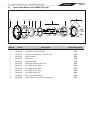
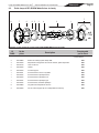
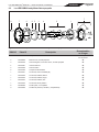
9.2 Jandy Small WaterColors RGBW LED Light
1 2
3
5
467
9
1
4 2
3
6
7
7
9
7
5
8
8
8
8
Figure 12. Jandy Small WaterColors RGBW LED Light Exploded View
DWG # Part # Description Field Replaceable
1 N/A WaterColors RGBW LED Light Housing NO - Purchase New Light
2 R0739600 Light Engine, Small LED Light YES
3 R0739700 Diverger, Light Shaping, Small LED Light YES
4 R0791100 Silicone Gasket YES
5 R0791200 Glass Lens YES
6 R0791300 Clamp Assembly YES
7 R0791401 Face Ring, Stainless Steel (SS) YES
7 R0791402 Face Ring, Plastic, White YES
7 R0791403 Face Ring, Plastic, Black YES
7 R0791404 Face Ring, Plastic, Gray YES
7 R0791405 Face Ring, Plastic Set YES
8 R0790900 Pilot Screw, with Retainer YES
9 R0791600 Clamp Screws (6 Screws and 6 Retainers) YES

Zodiac Pool Systems LLC
2882 Whiptail Loop # 100
Carlsbad, CA 92010, USA
Jandy.com | 1.800.822.7933
Zodiac Pool Systems Canada, Inc.
2-3365 Mainway
Burlington, ON L7M 1A6, Canada
Jandy.ca | 1.800.822.7933
A Fluidra Brand
©2022 Zodiac Pool Systems LLC. All rights reserved. ZODIAC®
is a registered
trademark of Zodiac International, S.A.S.U., used under license. All other
trademarks are the property of their respective owners.
H0596700_REVD
ETL LISTED
CONFORMS TO
UL STD 676
Certified to
CAN/CSA STD
C22.2 No. 89

FRANÇAIS
MANUEL D’INSTALLATION ET
DE FONCTIONNEMENT
Lampes à DEL RGBW WaterColors
Lampes immergées de grande et petite taille
H0596700_REVD
AVERTISSEMENT
POUR VOTRE SÉCURITÉ – L'installation et l'entretien de ce produit doivent être effectués par un technicien agréé
et certifié pour la réparation des équipements de piscine dans le territoire de compétence dans lequel ledit produit
est installé lorsque de telles exigences locales, provinciales, territoriales ou d’État existent. Le responsable
de l'entretien doit être un professionnel ayant une expérience suffisante dans l'installation et l'entretien des
équipements de piscine de manière à ce que les consignes du présent manuel puissent être suivies à la lettre.
Avant d'installer ce produit, prière de lire et de respecter toutes les consignes de mise en garde et les instructions
comprises avec ce produit. Le non-respect des mises en garde et des instructions pourrait causer des dommages
matériels, des blessures ou même la mort. L'installation ou l'utilisation inappropriée annulera la garantie.
L'installation ou l'utilisation inappropriée peuvent créer un danger électrique indésirable,
lequel peut entraîner des blessures graves, des dommages matériels ou la mort.
À L'ATTENTION DE L'INSTALLATEUR – Le présent manuel contient des renseignements
importants sur l'installation, le fonctionnement et la sécurité de ce produit. Ces renseignements
doivent être donnés au propriétaire ou à l'utilisateur de cet appareil.

Page 18 FRANÇAIS Lampes à DEL RGBW WaterColors de Jandy® | Manuel d’installation et de fonctionnement
Déclaration de conformité réglementaire de la FCC
Cet appareil est conforme à la section 15 des règles de la FCC. L’opération est soumise aux deux conditions
suivantes :
(1) Cet appareil ne doit pas causer d’interférences nuisibles, et
(2) cet appareil doit accepter toute interférence reçue, y compris les interférences susceptibles de provoquer un
fonctionnement indésirable. Ce dispositif doit être installé pour fournir une distance de séparation d’au moins 20
cm par rapport à toutes les personnes et ne doit pas être installé ou utilisé en conjonction avec une autre antenne
ou un autre émetteur, sauf conformément aux directives de la FCC concernant les produits multi-émetteurs.
MISE EN GARDE: Des modications non autorisées par le fabricant qui sont apportées à cet équipement peuvent
annuler le droit de l’utilisateur à utiliser cet équipement.
REMARQUE: Cet équipement a été testé et déclaré conforme aux limites d’un appareil numérique de classe
B, conformément à la section 15 des règles de la FCC. Ces limites sont conçues pour fournir une protection
raisonnable contre les interférences nuisibles dans une installation résidentielle. Cet équipement génère, utilise
et peut émettre de l’énergie par radiofréquence et, s’il n’est pas installé et utilisé conformément aux instructions,
peut provoquer des interférences nuisibles aux communications radio. Toutefois, il n’y a aucune garantie que des
interférences ne se produiront pas dans une installation particulière. Si cet équipement provoque des interférences
nuisibles à la réception de la radio ou de la télévision, ce qui peut être déterminé en éteignant et en rallumant
l’équipement, l’utilisateur est encouragé à essayer de corriger les interférences en appliquant une ou plusieurs des
mesures suivantes:
• Réorienter ou déplacer l’antenne de réception.
• Augmenter l’écart entre l’équipement et le récepteur.
• Connecter l’équipement à une pise sur un circuit diérent de celui auquel le récepteur est connecté.
• Consulter le revendeur ou un technicien de radio ou de télévision expérimenté pour obtenir de l’aide.
Table des matières
Section 1. Consignes de sécurité ...................... 19
Section 2. Description du produit et
numéros de modèles .......................... 20
Section 3. Installation du luminaire de Jandy
pour une nouvelle construction ........ 21
3.1 Préparation du luminaire pour l’installation ..... 21
3.2 Installation du luminaire ................................... 22
Section 4. Remplacement d’un luminaire
de Jandy dans une piscine ou
un spa existant ................................... 22
4.1 Préparation du luminaire pour le
remplacement ................................................... 22
4.2 Remplacement du luminaire ............................ 23
Section 5. Options de câblage pour le
contrôle des lampes à DEL
WaterColors de Jandy ........................ 23
5.1 Câblage à un système de contrôle
Aqualink® RS .................................................... 24
5.2 Câblage à une minuterie ................................. 24
5.3 Câblage à un interrupteur ................................ 24
Section 6. Mode d’emploi de la lampe à DEL
RGBW WaterColors de Jandy ........... 24
6.1 Pour faire fonctionner la lampe et changer
les couleurs ...................................................... 24
6.2 Pour réinitialiser la séquence de couleurs ....... 26
Section 7. Remplacement de la carte et
du moteur de DEL
(carte de circuits imprimés) ............... 26
7.1 Retrait du crochet-support de piscine. .............. 26
7.2 Remplacement du moteur de la petite
lampe de 12 V (carte de circuits imprimés) .......26
7.3 Remplacement de la petite carte à
DEL de 120 V ................................................... 27
7.4 Remplacement du moteur de la petite
lampe de 120 V (carte de circuits imprimés) .... 27
7.5 Remplacement du moteur de la grande
lampe (carte de circuits imprimés)
(120 V et 12 V) ................................................. 27
7.6 Réassemblage du luminaire. ........................... 27
7.7 Réinstallation du luminaire de Jandy
dans la niche. ................................................... 29
Section 8. Installation 12 volts ........................... 29
Section 9. Vue éclatée et pièces
de rechange ....................................... 30
9.1 Grande lampe à DEL RGBW WaterColors
de Jandy ........................................................... 30
9.2 Petite lampe à DEL RGBW WaterColors
de Jandy ........................................................... 31

Page 19
FRANÇAIS
Lampes à DEL RGBW WaterColors de Jandy® | Manuel d’installation et de fonctionnement
Section 1. Consignes de sécurité
DIRECTIVES DE SÉCURITÉ IMPORTANTES RELATIVES À UN RISQUE D’INCENDIE,
DE DÉCHARGE ÉLECTRIQUE OU DE BLESSURE.
LIRE ET SUIVRE TOUTES LES DIRECTIVES
Au moment de l'installation et de l'utilisation de cet équipement électrique, des précautions de base doivent toujours être suivies,
entre autres :
AVERTISSEMENT
RISQUE DE DÉCHARGE ÉLECTRIQUE OU D'ÉLECTROCUTION. Cette lampe immergée doit être installée
par un électricien agréé ou certifié en accord avec le Code national de l'électricité américain (National Electrical Code, ou
NEC) et avec les autres codes et règlements applicables à l'échelle locale. Une installation inappropriée peut causer des
dommages matériels et entraîner un risque de danger électrique (décharge électrique ou électrocution) pouvant causer
des blessures graves et même la mort des installateurs ou des utilisateurs de la piscine ou du spa. Lisez et respectez les
instructions détaillées ci-dessous.
AVERTISSEMENT
Avant d'installer la lampe immergée, lisez et respectez toutes les consignes de mise en garde et les instructions incluses
avec cette lampe. Toute effraction à ces consignes de sécurité et instructions peut causer des blessures graves ou mortelles,
ou des dommages matériels. Composez le +1-707-776-8200 pour recevoir gratuitement des manuels de consignes de
sécurité supplémentaires.
MISE EN GARDE
Sauf dans le cas où les lampes à DEL RGBW WaterColors de Jandy sont installées dans une zone de la piscine qui n’est pas
utilisée pour nager et où la lentille est protégée de façon adéquate pour empêcher qu’une personne entre en contact avec
elle, la lampe doit être installée dans un mur de la piscine ou sur celui-ci, avec le haut de l’ouverture de la lentille au moins à
457 mm (18 po) sous le niveau d’eau normal de la piscine.
À L’ATTENTION DE L’INSTAL
Ce manuel contient des renseignements importants concernant l'installation, le fonctionnement et les
consignes de sécurité pour ce produit. Ces renseignements doivent être donnés au propriétaire ou à
l'utilisateur de cet appareil.
AVIS
Les lampes à DEL RGBW WaterColors de Jandy sont conçues pour être installées dans les piscines d’eau douce et d’eau
salée. Assurez-vous que les niches immergées dans lesquelles les lampes doivent être installées sont conçues pour
l'utilisation appropriée : eau douce ou eau salée.
CONSERVER CES DIRECTIVES

Page 20 FRANÇAIS Lampes à DEL RGBW WaterColors de Jandy® | Manuel d’installation et de fonctionnement
Section 2. Description du produit et numéros de modèles
N° de modèle Taille de la lampe
WaterColors Tension Ampères Longueur
des câbles
Matériau de
l’anneau frontal
CPLVRGBWS30 Grande 12 V CA 4.0 9,14 m (30 pi) Acier inoxydable
CPLVRGBWS50 Grande 12 V CA 4.0 15,24 m (50 pi) Acier inoxydable
CPLVRGBWS100 Grande 12 V CA 4.0 30,48 m (100 pi) Acier inoxydable
CPLVRGBWP100 Grande 12 V CA 4.0 30,48 m (100 pi) Plastique
CPLVRGBWS50C Grande 12 V CA 4.0 15,24 m (50 pi) Acier inoxydable
CPLVRGBWS100C Grande 12 V CA 4.0 30,48 m (100 pi) Acier inoxydable
CPLVRGBWP100C Grande 12 V CA 4.0 30,48 m (100 pi) Plastique
CPHVRGBWS30 Grande 120 V CA 0.4 9,14 m (30 pi) Acier inoxydable
CPHVRGBWS50 Grande 120 V CA 0.4 15,24 m (50 pi) Acier inoxydable
CPHVRGBWS100 Grande 120 V CA 0.4 30,48 m (100 pi) Acier inoxydable
CPHVRGBWP100 Grande 120 V CA 0.4 30,48 m (100 pi) Plastique
CPHVRGBWS150 Grande 120 V CA 0.4 45,72 m (150 pi) Acier inoxydable
CPHVRGBWS250 Grande 120 V CA 0.4 76,2 m (250 pi) Acier inoxydable
CPHVRGBWS50C Grande 120 V CA 0.4 15,24 m (50 pi) Acier inoxydable
CPHVRGBWS100C Grande 120 V CA 0.4 30,48 m (100 pi) Acier inoxydable
CPHVRGBWP100C Grande 120 V CA 0.4 30,48 m (100 pi) Plastique
CSLVRGBWS30 Petite 12 V CA 2.0 9,14 m (30 pi) Acier inoxydable
CSLVRGBWS50 Petite 12 V CA 2.0 15,24 m (50 pi) Acier inoxydable
CSLVRGBWS100 Petite 12 V CA 2.0 30,48 m (100 pi) Acier inoxydable
CSLVRGBWP100 Petite 12 V CA 2.0 30,48 m (100 pi) Plastique
CSLVRGBWS50C Petite 12 V CA 2.0 15,24 m (50 pi) Acier inoxydable
CSLVRGBWS100C Petite 12 V CA 2.0 30,48 m (100 pi) Acier inoxydable
CSLVRGBWP100C Petite 12 V CA 2.0 30,48 m (100 pi) Plastique
CSHVRGBWS30 Petite 120 V CA 0.2 9,14 m (30 pi) Acier inoxydable
CSHVRGBWS50 Petite 120 V CA 0.2 15,24 m (50 pi) Acier inoxydable
CSHVRGBWS100 Petite 120 V CA 0.2 30,48 m (100 pi) Acier inoxydable
CSHVRGBWP100 Petite 120 V CA 0.2 30,48 m (100 pi) Plastique
CSHVRGBWS150 Petite 120 V CA 0.2 45,72 m (150 pi) Acier inoxydable
CSHVRGBWS250 Petite 120 V CA 0.2 76,2 m (250 pi) Acier inoxydable
CSHVRGBWS50C Petite 120 V CA 0.2 15,24 m (50 pi) Acier inoxydable
CSHVRGBWS100C Petite 120 V CA 0.2 30,48 m (100 pi) Acier inoxydable
CSHVRGBWP100C Petite 120 V CA 0.2 30,48 m (100 pi) Plastique
La page est en cours de chargement...
La page est en cours de chargement...
La page est en cours de chargement...
La page est en cours de chargement...
La page est en cours de chargement...
La page est en cours de chargement...
La page est en cours de chargement...
La page est en cours de chargement...
La page est en cours de chargement...
La page est en cours de chargement...
La page est en cours de chargement...
La page est en cours de chargement...
La page est en cours de chargement...
La page est en cours de chargement...
La page est en cours de chargement...
La page est en cours de chargement...
La page est en cours de chargement...
La page est en cours de chargement...
La page est en cours de chargement...
La page est en cours de chargement...
La page est en cours de chargement...
La page est en cours de chargement...
La page est en cours de chargement...
La page est en cours de chargement...
La page est en cours de chargement...
La page est en cours de chargement...
La page est en cours de chargement...
La page est en cours de chargement...
-
 1
1
-
 2
2
-
 3
3
-
 4
4
-
 5
5
-
 6
6
-
 7
7
-
 8
8
-
 9
9
-
 10
10
-
 11
11
-
 12
12
-
 13
13
-
 14
14
-
 15
15
-
 16
16
-
 17
17
-
 18
18
-
 19
19
-
 20
20
-
 21
21
-
 22
22
-
 23
23
-
 24
24
-
 25
25
-
 26
26
-
 27
27
-
 28
28
-
 29
29
-
 30
30
-
 31
31
-
 32
32
-
 33
33
-
 34
34
-
 35
35
-
 36
36
-
 37
37
-
 38
38
-
 39
39
-
 40
40
-
 41
41
-
 42
42
-
 43
43
-
 44
44
-
 45
45
-
 46
46
-
 47
47
-
 48
48


Jandy WaterColors RGBW LED Lights Manuel utilisateur
- Catégorie
- Accessoires de piscine hors terre
- Taper
- Manuel utilisateur
dans d''autres langues
Documents connexes
-
Jandy H0596700_B Manuel utilisateur
-
-
Jandy 400120 Manuel utilisateur
-
Jandy SMARTSYNC60W Manuel utilisateur
-
-
Jandy iAquaLink 3.0 Mode d'emploi
-
Jandy LXI Mode d'emploi
-