

MXP8PN24 – Installation and User Guide
Document Number: 80782-4
Issue: 1
Spellman High Voltage Electronics Limited | +44 (0)1798 877000 | hvsales@spellmanhv.co.uk | Broomers Park, Pulborough, W. Sussex, UK. RH20 2RY
TEMPLATE: 40776 ISS B | ECN I-10887 | DATE: 05/11/2021
QA/ENG/SAL
© 2021 Spellman High Voltage Electronics Corporation
Page 2 of 10
Change History
Contents
1. Unit Description ..........................................................................................................................................5
1.1 Unit Ratings ......................................................................................................................................5
1.1.1 Power Input..................................................................................................................................5
1.1.2 HV Output ....................................................................................................................................5
1.2 Environmental conditions..................................................................................................................5
2. Safety .........................................................................................................................................................6
2.1 Unit Grounding ..................................................................................................................................6
3. Installing the Unit........................................................................................................................................7
3.1 Initial Inspection ................................................................................................................................7
3.2 Electrical Installation .........................................................................................................................7
3.3 Connections and Unit Operation ......................................................................................................8
3.3.1 Input / Output Molex Mini-Fit Jr connector…………………………………………………………...8
3.3.2 HV Output Connector ..................................................................................................................9
3.4 Mechanical Installation .....................................................................................................................9
Appendix A - Mechanical layout ...................................................................................................................... 10
ISSUE
DATE
NAME
SECTION
CHANGE
1
15/Nov/2021
JS
All
All
3.3
Created from 80398-4
Template updated
Added connectors details and pinout indication

MXP8PN24 – Installation and User Guide
Document Number: 80782-4
Issue: 1
Spellman High Voltage Electronics Limited | +44 (0)1798 877000 | hvsales@spellmanhv.co.uk | Broomers Park, Pulborough, W. Sussex, UK. RH20 2RY
TEMPLATE: 40776 ISS B | ECN I-10887 | DATE: 05/11/2021
QA/ENG/SAL
© 2021 Spellman High Voltage Electronics Corporation
Page 3 of 10
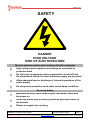
SAFETY
DANGER
HIGH VOLTAGE
RISK OF ELECTROCUTION
Observe extreme caution when working with this equipment
High voltage power supplies must always be connected to
protective earth
Do not touch connections unless equipment is turned off and
the capacitance of both the load and power supply are grounded
Allow adequate time for discharge of internal capacitance of the
power supply
Do not ground yourself or work under wet or damp conditions
Servicing Safety
Maintenance may require removing the Instrument cover with
the power on
Servicing should only be done by qualified personnel aware of
the hazards
Return to supplier for servicing

MXP8PN24 – Installation and User Guide
Document Number: 80782-4
Issue: 1
Spellman High Voltage Electronics Limited | +44 (0)1798 877000 | hvsales@spellmanhv.co.uk | Broomers Park, Pulborough, W. Sussex, UK. RH20 2RY
TEMPLATE: 40776 ISS B | ECN I-10887 | DATE: 05/11/2021
QA/ENG/SAL
© 2021 Spellman High Voltage Electronics Corporation
Page 4 of 10
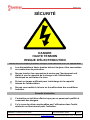
SÉCURITÉ
DANGER
HAUTE TENSION
RISQUE D'ÉLECTROCUTION
Observez une extrême prudence lorsque vous travaillez avec cet équipement
Les alimentations haute tension doivent toujours être connectées
au conducteur de protection.
Ne pas toucher les connexions à moins que l'équipement soit
éteint et que la capacité de la charge et de l'alimentation
électrique ne soit mise à la terre.
Prévoir un temps suffisant pour la décharge de la capacité
interne de l'alimentation.
Ne pas vous mettre à la terre ou travailler dans des conditions
humides.
Sécurité d'entretien
L'entretien ne doit être effectué que par un personnel qualifié et
conscient des dangers.
Il n'y a pas de piéce remplaçables par l'utilisateur dans l'unité,
retourner au fournisseur pour l'entretien.

MXP8PN24 – Installation and User Guide
Document Number: 80782-4
Issue: 1
Spellman High Voltage Electronics Limited | +44 (0)1798 877000 | hvsales@spellmanhv.co.uk | Broomers Park, Pulborough, W. Sussex, UK. RH20 2RY
TEMPLATE: 40776 ISS B | ECN I-10887 | DATE: 05/11/2021
QA/ENG/SAL
© 2021 Spellman High Voltage Electronics Corporation
Page 5 of 10
1. Unit Description
Spellman's MX8 Plus is a well-regulated high performance fast reversible supply featuring a 25ms "hot
switchable" polarity reversing capability. This unit consist of one chassis containing the HV output and
control circuits for building into the final system.
The current return paths are to the chassis, which is grounded to the system earth by fixings.
Control and monitoring is via a hard-wired interface connector
1.1 Unit Ratings
1.1.1 Power Input
Voltage: 24 Vdc ± 10%
Current: <500mA nominal continuous
<1200mA peak during reversing
1.1.2 HV Output
Voltage: ± 8 kVdc
Current: 100µA maximum
1.2 Environmental conditions
Operating Temperature: 5°C to +45°C
Storage Temperature: -35°C to +85°C. A conditioning period of three hours minimum is
required after exposure to Storage Temperatures.
Humidity: 0% to 80% RH (non-condensing)
Altitude: 2000m ASL at full power

MXP8PN24 – Installation and User Guide
Document Number: 80782-4
Issue: 1
Spellman High Voltage Electronics Limited | +44 (0)1798 877000 | hvsales@spellmanhv.co.uk | Broomers Park, Pulborough, W. Sussex, UK. RH20 2RY
TEMPLATE: 40776 ISS B | ECN I-10887 | DATE: 05/11/2021
QA/ENG/SAL
© 2021 Spellman High Voltage Electronics Corporation
Page 6 of 10
2. Safety
The HV outputs of the unit are hazardous and the conditions of this manual must be complied with to
maintain safety. Operating the unit in a manner not specified in this manual may impair the protection
against electric shock provided by the unit.
The unit is contained in an earthed case. The unit shall be properly bonded to the main protective earth
termination in the end product via the case.
The unit has been evaluated for use in a Pollution Degree 2, Installation Category II environment.
Consideration should be given to conducting the following tests with the unit installed in the end product:
• Dielectric Voltage Withstand Test, between live parts of the unit and the end product chassis.
• Permissible Limits Tests with the unit installed in the end product.
• Temperatures on power electronic components, transformer windings and accessible surfaces.
Meaning of Symbols
SYMBOL
MEANING
Refer to manual before operating
Caution, possibility of electric shock
Protective conductor terminal (PE)
Functional Earth
2.1 Unit Grounding
The unit is contained in an earthed case. The case of the unit shall be properly bonded to the main
protective earth termination in the end product.

MXP8PN24 – Installation and User Guide
Document Number: 80782-4
Issue: 1
Spellman High Voltage Electronics Limited | +44 (0)1798 877000 | hvsales@spellmanhv.co.uk | Broomers Park, Pulborough, W. Sussex, UK. RH20 2RY
TEMPLATE: 40776 ISS B | ECN I-10887 | DATE: 05/11/2021
QA/ENG/SAL
© 2021 Spellman High Voltage Electronics Corporation
Page 7 of 10
3. Installing the Unit
3.1 Initial Inspection
Inspect the package exterior for evidence of damage due to handling in transit. Notify the carrier and
Spellman immediately if damage is evident. Do not destroy or remove any of the packing material used
in a damaged shipment.
After unpacking, inspect the panel and chassis for visible damage.
Note: Failure to comply with the above could compromise the safe operation of the unit and invalidate
the warranty.
3.2 Electrical Installation
The unit is designed for indoor use and is to be supplied from a double insulated, UL recognised, 24V
dc supply.
The units must be terminated safely before operation. Hazardous voltages will be exposed if the
connector is removed whilst the unit is enabled.
The unit must be switched off for at least one minute before disconnecting any of the connectors.
The unit shall be properly bonded to the main protective earthing termination in the end product using
the bolt down point.
The input and output connectors are not intended for field connections and should only be connected to
internal wiring in the end use equipment.
The unit is intended for use as a component and no surface of the unit should be accessible in the end
product.
The unit is contained in an enclosed case and can be mounted in any orientation. A cooling air flow is
recommended.

MXP8PN24 – Installation and User Guide
Document Number: 80782-4
Issue: 1
Spellman High Voltage Electronics Limited | +44 (0)1798 877000 | hvsales@spellmanhv.co.uk | Broomers Park, Pulborough, W. Sussex, UK. RH20 2RY
TEMPLATE: 40776 ISS B | ECN I-10887 | DATE: 05/11/2021
QA/ENG/SAL
© 2021 Spellman High Voltage Electronics Corporation
Page 8 of 10
3.3 Connections and Unit Operation
3.3.1 Input / Output Molex Mini-Fit Jr connector
pin#
Signal
I/O
Description
1
+24VDC
I
DC in
2
+24VDC Return
I
Ground return for DC in
3
Enable
I
enable/inhibit input. TTL high is enabled, TTL low is disabled*
4
Vmon
O
output voltage monitor. 0 to +8V for 0V to ±8kV output (accuracy
±1% of max output, always positive) Output impedance 10kΩ
5
Vprog
I
voltage control input. 0 to +8V for 0V to ±8kV output (accuracy
±1% of max output, always positive)
6
Imon
O
current monitor output. 0 - 10V for 0A to 100µA (accuracy ±2%
of max output, always positive). Output impedance 10kΩ.
7
Iprog
I
current control input. 0 to +10V for 0A to 100µA (accuracy ±1%
of max output, always positive)
8
Polarity control
I
polarity control input. TTL high is positive, TTL low is negative*
9
Analog Ground
-
analogue ground
10
V/I Indicator
O
current/voltage control indicator. TTL compatible output (3.3V
max). TTL high when in current mode. TTL low when in voltage
mode. Output impedance 1kΩ.
11-14
Pins not used
*Note: TTL input. The threshold is set to 1.65V for use with 3.3V or 5V input levels although the input
will tolerate up to 15V being applied.
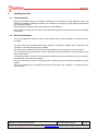
Receptacle: Molex Mini-Fit Jr., Dual Row, 14 Circuits. Series: 5557 Part number : 39-01-2140
Mating connector is not provided.
Please see Molex product page for range of mating connectors (for example Molex part number 39-
01-2141) and crimps (for example Molex part number 39-00-0040):
(https://www.molex.com/molex/products/part-detail/crimp_housings/0039012140)
Cable: FS cables 12 core braid screen 7-2-12C Part number: 39300212 Length: 508 mm
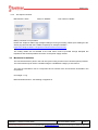
Receptacle pinout:

MXP8PN24 – Installation and User Guide
Document Number: 80782-4
Issue: 1
Spellman High Voltage Electronics Limited | +44 (0)1798 877000 | hvsales@spellmanhv.co.uk | Broomers Park, Pulborough, W. Sussex, UK. RH20 2RY
TEMPLATE: 40776 ISS B | ECN I-10887 | DATE: 05/11/2021
QA/ENG/SAL
© 2021 Spellman High Voltage Electronics Corporation
Page 9 of 10
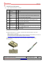
3.3.2 HV Output Connector
Manufacturer: Alden Series: F-SERIES Part number: F303RX
Mating connector is not provided.
Please see Amphenol Alden High Voltage Catalogue for range of mating cables (from Catalogue: all F
Series plug will mate with the F303RX receptacle) for example F602RX”L”.
https://www.amphenolalden.com/products-solutions/technical-resources
The mating cables are not shielded so the load return must be provided through adequate low
impedance and shortest possible connection to the power supply chassis.
3.4 Mechanical Installation
The unit shall be fixed in place in the end user system using screws on the hold down points provided.
The units should only be used in a Pollution Degree 2 Installation Category II environment.
The units are intended for use as a component and no surface of the unit should be accessible in the
end product.
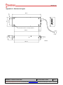
Unit weight: 1.1 kg
Mechanical Dimensions - see drawing in Appendix A

MXP8PN24 – Installation and User Guide
Document Number: 80782-4
Issue: 1
Spellman High Voltage Electronics Limited | +44 (0)1798 877000 | hvsales@spellmanhv.co.uk | Broomers Park, Pulborough, W. Sussex, UK. RH20 2RY
TEMPLATE: 40776 ISS B | ECN I-10887 | DATE: 05/11/2021
QA/ENG/SAL
© 2021 Spellman High Voltage Electronics Corporation
Page 10 of 10
Appendix A - Mechanical layout
8-32 UNC inserts x 7mm deep (6 posns)
240.0
205.74
205.74
82.0
57.15 12.4
17.1
18.8
37.6
71224rA
-
 1
1
-
 2
2
-
 3
3
-
 4
4
-
 5
5
-
 6
6
-
 7
7
-
 8
8
-
 9
9
-
 10
10


