Signature UPFXC2466S Le manuel du propriétaire
- Catégorie
- Frigos
- Taper
- Le manuel du propriétaire

ENGLISH FRANÇAIS ESPAÑOL
OWNER’S MANUAL
FRENCH DOOR REFRIGERATOR
Please read this owner's manual thoroughly before operating
and keep it handy for reference at all times.
UPFXC2466S
www.thesignaturekitchen.com

TABLE OF CONTENTS 2
TABLE OF CONTENTS
3
IMPORTANT SAFETY INSTRUCTIONS
4 PRODUCT OVERVIEW
4 Refrigerator Exterior
5 Refrigerator Interior
6 INSTALLATION
6 Installation Overview
6
Product Specifications
7 Unpacking the Refrigerator
7 Choosing the Proper Location
8 Measuring Clearances
8 Removing/Assembling the Refrigerator Door
Handles
9 Removing/Assembling the Freezer Drawer
Handle
9 Removing/Assembling the Doors and
Drawers
10
Removing the Left Refrigerator Door
11
Removing the Right Refrigerator Door
12
Assembling the Right Refrigerator Door
13
Assembling the Left Refrigerator Door
14
Removing the Freezer Drawers
16
Assembling the Freezer Drawers
17 Connecting the Water Line
17
Before You Begin
17
Water Pressure
17
What You Will Need
18
Water Line Installation Instructions
20 Turning On the Power
21 Leveling and Door Alignment
21
Leveling
21
Door Alignment

3 IMPORTANT SAFETY INSTRUCTIONS
SAVE THESE INSTRUCTIONS
CAUTION
Installation
The refrigerator must be properly installed
y
in accordance with the Installer Instructions
that were taped to the front of the
refrigerator.
Be careful when you unpack and install the
y
refrigerator. Immediately dispose of plastic
and other packing materials out of reach of
children.
The appliance must be positioned for easy
y
access to a power source.
Use
Close the door carefully when children are
y
around.
Keep fingers out of pinch point areas;
y
clearances between the doors and cabinets
are necessarily small. Be careful closing
doors when children are nearby.
If you store food improperly, be aware that it
y
may fall and cause injury.
Do not use aerosols near the refrigerator.
y
Do not store articles on the top of the
y
appliance.
Maintenance
Do not use strong detergents like wax or
y
thinners for cleaning. Clean with a soft cloth.
Wipe foreign objects (such as dust and
y
water) off the prongs of the power plug and
contact areas regularly.
Do not store, disassemble or repair the
y
refrigerator by yourself.
Remove any dust or foreign matter from the
y
power plug pins.
Do not use a wet or damp cloth when
y
cleaning the plug.
If the refrigerator is disconnected from the
y
power supply, you should wait for at least
five minutes before plugging it back in.
If you notice a chemical or burning plastic
y
smell or see smoke, unplug the refrigerator
immediately and contact your Signature
Kitchen Suite Service Center.
READ ALL INSTRUCTIONS BEFORE USING THE APPLIANCE.
To reduce the risk of fire, electric shock, or personal injury when using your product, basic safety
precautions should be followed, including the following:
IMPORTANT SAFETY INSTRUCTIONS

PRODUCT OVERVIEW 4
ENGLISH
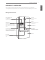
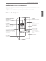
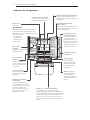
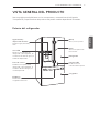
PRODUCT OVERVIEW
Use this page to become more familiar with the parts and features of your refrigerator.
*The appearance and specifications of the actual product may differ depending on the model.
Refrigerator Exterior
Filtered Water and
Ice Dispenser
Dispenses purified water and ice.
LED Display
Displays the refrigerator and
freezer temperature, the water
filter condition and the dispenser
status.
Control Panel
Sets the refrigerator and freezer
temperatures, the water filter
condition and the dispenser mode.
Refrigerator
Freezer
Ez Handle
Easily opens the freezer
door.
LED Light
LED lights up when the
freezer door is opened.
Button
Opens the Door-in-Door
compartment
Handle
Opens and closes
the door.

5 PRODUCT OVERVIEW
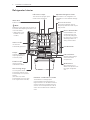
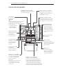
Refrigerator Interior
Water filter
Purifies water.
NOTE
Replace the water filter every 6 months, or
as needed. See Replacing the Filter in this
manual for details.
* (Water filter is only
available on some
models.)
Indoor Ice Bin
Ice cubes are
automatically produced.
Crisper
Controls humidity and
helps vegetables and
fruit to stay crisp.
Auto Closing Hinge
The refrigerator doors
and freezer drawers close
automatically when pushed
slightly.
(The door only closes
automatically when it is open
at an angle of less than 30°.)
Fixed Door Bin
Used to preserve
chilled food or drinks.
Durabase® and Durabase® Divider
The Durabase is a storage space
recommended for the preservation of
large food items. The Durabase Divider is
used to organize the Durabase area into
sections. It can be adjusted from side to
side to accommodate items of different
sizes.
Glide‘N’Serve
Store food items at a
different temperature than
the regular refrigerator
area.
Pullout Drawers
Used for extra storage
within the freezer
compartment.
LED interior lamps
The interior lamps light up the
inside of the refrigerator.
Door-In-Door Case
A convenient storage area for
frequently-used items that require
easy access.
Adjustable Refrigerator Shelf
The shelves in the refrigerator are
adjustable to meet individual storage
needs.
Cheese & Butter Bin
Cheese & Butter and
Condiment bins, that
are specially designed
for these items, making
spreading butter and
slicing cheese easier.
Condiment Bin

INSTALLATION 6
ENGLISH
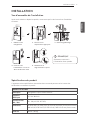
INSTALLATION
Installation Overview
Read the following installation instructions first after purchasing this product or transporting it to
another location.
1 Unpacking your
refrigerator
2 Choosing the proper
location
3 Disassembling/Assembling
4 Connecting the water
supply and water line
5 Leveling and Door
Alignment
NOTE
Connect to potable water supply
only.
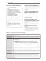
Product Specifications
The appearance and specifications listed in this manual may vary due to constant product
improvements.
Models UPFXC2466S
Description French door refrigerator
Electrical requirements 115 VAC @ 60 Hz
Min. / Max. Water pressure
20 – 120 psi (138 – 827 kPa)
Dimensions
35 3/4” (W) X 30 7/8” (D) X 70 1/4” (H), 42 3/4” (D w/ door open)
908 mm (W) X 785 mm (D) X 1785 mm (H), 1085 mm (D w/ door open)
Net weight 328 lb. (149 kg)

7 INSTALLATION
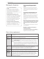
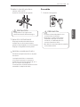
Unpacking the Refrigerator
Choosing the Proper Location
WARNING
Use two or more people to move and
y
install the refrigerator. Failure to do so
can result in back or other injury.
Your refrigerator is heavy. When moving
y
the refrigerator for cleaning or service,
be sure to protect the floor. Always pull
the refrigerator straight out when moving
it. Do not wiggle or walk the refrigerator
when trying to move it, as floor damage
could occur.
Keep flammable materials and vapors,
y
such as gasoline, away from the
refrigerator. Failure to do so can result in
fire, explosion, or death.
Remove tape and any temporary labels from
y
your refrigerator before using.
Do not remove any warning labels, the model
and serial number label, or the Tech Sheet that
is located under the front of the refrigerator.
To remove any remaining tape or glue, rub
y
the area briskly with your thumb.
Tape or glue residue can also be easily removed
by rubbing a small amount of liquid dish soap
over the adhesive with your fingers. Wipe with
warm water and dry.
Do not use sharp instruments, rubbing
y
alcohol, flammable fluids, or abrasive
cleaners to remove tape or glue.
These products can damage the surface of your
refrigerator.
Reinstall or adjust shelves as needed.
y
Refrigerator shelves are installed in the shipping
position. Reinstall shelves according to your
individual storage needs.
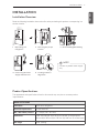
Water Water supply must be easily connected for the automatic icemaker.
Water pressure 20–120 psi on models without water filter. 40–120 psi on models with
water filter.
Electricity Use an individual, grounded outlet:115 Volts, 60 Hz, AC, 15 Amps
minimum.
WARNING:
Do not overload house wiring and cause a fire
hazard by plugging in multiple appliances in the same outlet
with the refrigerator. To reduce the risk of electric shock, do
not install the refrigerator in a wet or damp area.
Floor Floor must be level and solidly constructed. Adjust the leveling legs to
compensate for any unevenness in the floor. Do not install on carpeting,
soft tile, a platform, or a weakly supported structure.
Ambient
temperature
Temperature must be between 55°F (13°C) and 110°F (43°C). If the
ambient temperature is too low or high, performance may be affected.
Clearances Allow at least 24 in. (61 cm) in front to open the doors. Allow at least
2 in. (5.08 cm) between the back of the refrigerator and the wall. If the
refrigerator is too close to adjacent items, freezing capability may decrease
and electricity consumption may increase.

INSTALLATION 8
ENGLISH
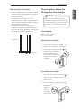
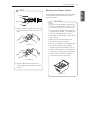
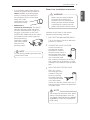
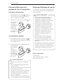
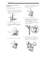
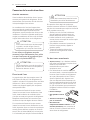
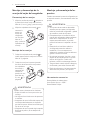
Removing the Handles
1
Loosen the set screws with a
3
/
32
in.
Allen wrench and remove the handle.
2
Loosen the mounting fasteners that
connect to the refrigerator
door and handle using
a
1
/
4
in. Allen wrench, and
remove the mounting
fasteners.
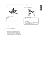
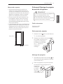
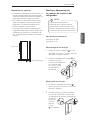
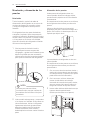
Measuring the Clearances
Check the dimensions of the product and the
y
installation path to ensure there is sufficient
room to move the refrigerator through doors
or narrow openings.
If an opening is too narrow to fit the
y
refrigerator through, remove the refrigerator
doors. See Removing/Assembling the Doors
and Drawers in this manual.
The installation location chosen for the
y
refrigerator should allow space behind the
unit for connections and airflow and space in
front to open the doors and drawers.
2” (5.08 cm)
24” (61 cm)
Removing/Assembling the
Refrigerator Door Handles
Tools Needed
3/32 in. Allen wrench
¼ in. Allen wrench
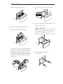
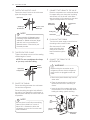
Assembling the Handles
1
Assemble the mounting fasteners at
both ends of the handle using a
1
/
4
in.
Allen wrench.
2
Place the handle on the door by fitting
the handle footprints over the mounting
fasteners and
tightening
the set
screws
with a
3
/
32
in.
Allen wrench.
NOTE
When it is necessary to move the
refrigerator through a narrow opening,
removing the doors is the recommended
procedure. If it is necessary to remove
the handles, follow the directions below.

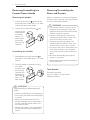
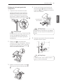
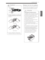
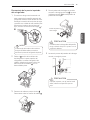
9 INSTALLATION
Tools Needed
Flat-head screwdriver
10 mm or 13/32 in. socket wrench
Phillips screwdriver
Removing/Assembling the
Freezer Drawer Handle
Removing the Handles
1
Loosen the set screws located on the
lower side of the handle with a
1
/
8
in. Allen
wrench and remove the handle.
2
Loosen the mounting fasteners that
connect to the
freezer drawer
and handle
using a
1
/
4
in.
Allen wrench,
and remove
the mounting
fasteners.
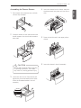
Assembling the Handles
1
Assemble the mounting fasteners at
both ends of the handle using a
1
/
4
in. Allen
wrench.
2
Place the handle on the door by fitting
the handle
footprints over
the mounting
fasteners and
tightening the
set screws
with a
1
/
8
in.
Allen wrench.
WARNING
If your entrance door is too narrow for the
y
refrigerator to pass through, remove the
refrigerator doors and move the refrigerator
sideways through the doorway.
Use two or more people to remove and
y
install the refrigerator doors. Failure to do
so can result in back or other injury.
Disconnect the electrical supply to the
y
refrigerator before installing. Failure to do
so could result in serious injury or death.
Do not put hands, feet or other objects into
y
the air vents or bottom of the refrigerator.
You may be injured or receive an electrical
shock.
Be careful when handling the hinge and
y
stopper, to avoid injury.
Remove food and bins before detaching the
y
doors and drawers.
Removing/Assembling the
Doors and Drawers
When it is necessary to move the refrigerator
through a narrow opening, removing the doors
is the recommended procedure.
WARNING
When assembling or disassembling the
handle:
Grasp the handle tightly to avoid dropping it.
y
Do not swing the handle into nearby people
y
or animals.
Make sure that the bracket hole of the
y
handle fits properly into the stopper bolt of
the door. Assemble the set screws to fix
the handle into place.
Make sure that there is not a gap between
y
the door and handle after assembling the
handle.

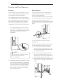
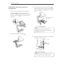
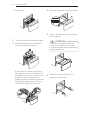
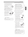
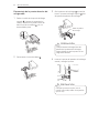
INSTALLATION 10
ENGLISH
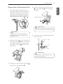
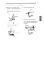
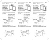
2
Remove the screw from the hinge cover
at the top of the refrigerator. Lift the hook
(not visible), located at the bottom of the
front side of the cover with a flat-head
screwdriver.
3
Remove the cover and pull out the tube .
Disconnect all wire harnesses
.
4
Rotate the hinge lever counterclockwise
. Lift the top hinge free of the hinge
lever latch.
CAUTION
When lifting the hinge free of the latch, be
careful that the door does not fall forward.
Hinge Lever Latch
5
Lift the door from the middle hinge pin and
remove the door.
CAUTION
Place the door, inside facing up, on a
non-scratching surface.
Removing the Left Refrigerator Door
1
The water supply is connected to the
upper right part of the rear surface of the
refrigerator. Remove the ring in the joint
area. Hold the water supply connection
and gently push the Collet to detach the
water supply line as shown in and .
NOTE
Detachment of the water supply line is
applicable only when detaching the left
refrigerator door.
Collet

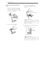
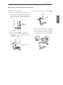
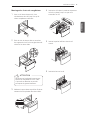
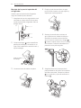
11 INSTALLATION
Removing the Right Refrigerator
Door
1
Remove the top hinge cover screw .
Lift the hook (not visible), located at the
bottom of the front side of the cover
,
with a flat-head screwdriver.
2
Detach the wire harness .
CAUTION
When lifting the hinge free of the hinge
lever latch, be careful that the door
does not fall forward.
Hinge Lever Latch
3
Rotate the hinge lever clockwise.
Lift the top hinge
free of the hinge
lever latch.
4
Lift the door from the middle hinge pin and
remove the door.
CAUTION
Place the door on the floor, inside
facing up, on a non-scratching surface.

INSTALLATION 12
ENGLISH
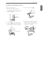
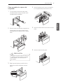
Install the right-side door first.
1
Make sure that the plastic sleeve is
inserted in the bottom of the door. Lower
the door onto the middle hinge pin as
shown in the figure.
2
Fit the hinge over the hinge lever latch
and slot it into place. Rotate the lever
counterclockwise to secure the hinge.
Assembling the Right Refrigerator Door
Hinge Lever Latch
4
Make sure that the door-switch located
inside the cover is tightly connected.
Position the cover in its place. Insert and
tighten the cover screw
.
3
Connect the wire harness .

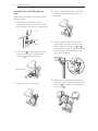
13 INSTALLATION
Assembling the Left Refrigerator
Door
Install the left refrigerator door after the right
door is installed.
1
Make sure that the plastic sleeve is
inserted in the bottom of the door. Install
the refrigerator door onto the middle hinge.
2
Fit the hinge over the hinge lever latch
and slot it into place. Rotate the lever
clockwise
and fasten the hinge.
3
Connect all the wire harnesses.
Hinge Lever Latch
4
Push the water supply tube into the hole
on the top case and pull it through the
backplate.
5
Hold the water supply connection and
gently push in the collet to connect the
water supply line as shown in
and .
Insert the tube at least
5
/
8
inch (15 mm) into
the connector. Assemble the clip to the
joint part for fastening.
6
Make sure that the door-switch located
inside the cover is tightly connected. Place
the cover in its position and tighten the
cover screw .
Collet

INSTALLATION 14
ENGLISH
CAUTION
Use two or more people to remove and
y
install the freezer drawer. Failure to do so
can result in back injury or other injury.
Do not hold the handle when removing
y
or replacing the drawer. The handle may
come off, resulting in personal injury.
Be careful of sharp hinges on both sides
y
of the drawer.
When you lay the drawer down, be
y
careful not to damage the floor.
Do not sit or stand on the freezer drawer.
y
To prevent accidents, keep children
y
and pets away from the drawer. Do not
leave the drawer open. If the Durabase
®
storage bin is removed from the freezer
drawer, there is sufficient space for a
small child or pet to crawl inside.
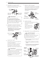
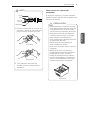
NOTE
1) Gently press the collet and insert the
tube until only one line shows on the
tube.
(Correct)
(Incorrect)
2) Pull the tube to make sure that the
tube is tightly fastened and then insert
the clip.
Removing the Freezer Drawers
In the following figures, the Pullout Drawers
located above the freezer drawer are not
shown for clarity.
Collet
Tube
Insert Line
Clip
(Durabase
®
)

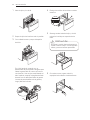
15 INSTALLATION
2
Pull the drawer open to full extension.
3
Gently lift and pull out the ice bin.
On the left rail, use a flat blade screwdriver
to push in on the tab to release the drawer
from the rail, as shown below. Once the
left side is loose, push the tab on the right
side with your finger to release the drawer.
Lift the front of the drawer up, then pull it
straight out.
4
Remove the screws from the rails at both
ends.
5
Grip both sides of the drawer and pull it up to
remove it from the rails.
6
Hold both rails and push them in
simultaneously.
CAUTION
Do not hold the handle when removing
or replacing the drawer. The handle may
come off, causing personal injury.
1
Open the drawer and pull out it.

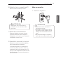
INSTALLATION 16
ENGLISH
4
Insert the drawer into the frame, and push
the drawer back into place until you hear a
click.
5
Place the ice bin back in the upper pullout
drawer.
6
Insert the drawer in the rail assembly.
Assembling the Freezer Drawers
1
Pull out both rails simultaneously, until both
rails are fully extended.
2
Grasp the drawer on each side and hook the
drawer supports into the rail tabs located on
both sides.
CAUTION
Do not hold the handle when removing
or replacing the drawer. The handle
may come off, causing personal injury.
3
Lower the door into its final position and
tighten the screws located on both sides.
Insert the Durabase basket in the rail
assembly.

17 INSTALLATION
CAUTION
Wear eye protection during installation
to prevent injury.
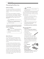
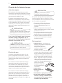
Connecting the Water Line
Before You Begin
This water line installation is not covered by the
refrigerator warranty. Follow these instructions
carefully to minimize the risk of expensive water
damage.
Water hammer (water banging in the pipes) in
house plumbing can cause damage to refrigerator
parts and can lead to water leakage or flooding.
Call a qualified plumber to correct water hammer
before installing the water supply line to the
refrigerator.
If you use your refrigerator before connecting
the water line, make sure the icemaker power
button is turned o.
Water Pressure
The water pressure must be between 20 and
120 psi. If the refrigerator is installed in an area
with low water pressure (below 20 psi), you can
install a booster pump to compensate for the low
pressure.
If a reverse osmosis water filtration system is
connected to your cold water supply, this water
line installation is not covered by the refrigerator
warranty. Follow the instructions carefully to
minimize the risk of expensive water damage.
If a reverse osmosis water filtration system is
connected to your cold water supply, the water
pressure to the reverse osmosis system needs
to be a minimum of 40 to 60 psi (276-414 kPa or
2.8-4.2 kgf/cm², less than 2-3 sec. to fill a cup of
7 oz or 198 cc capacity).
If the water pressure from the reverse osmosis
system is less than 20 psi or 138 kPa or 1.4 kgf/
cm² (takes more than 4 sec to fill a cup of 7 oz or
198 cc capacity):
Check to see if the sediment filter in
y
the reverse osmosis system is blocked.
Replace the filter if necessary.
Allow the storage tank on the reverse
y
osmosis system to refill after heavy
usage.
If the issue concerning water pressure
y
from reverse osmosis remains, call a
licensed, qualified plumber.
All installations must be in accordance
y
with local plumbing code requirements.
What You Will Need
Copper Tubing,
y
¼ in. outer diameter, to
connect the refrigerator to the water
supply. Be sure both ends of the tubing
are cut square.
To determine how
y
much tubing you need:
measure the distance
from the water valve on the back of
the refrigerator to the water supply
pipe. Then, add 8 feet (2.4 m). Be sure
there is sufficient extra tubing (about 8
feet [2.4 m] coiled into 3 turns of about
10 in. [25 cm] diameter) to allow the
refrigerator to move out from the wall
after installation.
Power drill.
y
½ in. or adjustable
y
wrench.
Flat blade and Phillips
y
head screwdrivers.
Two ¼ in. outer
y
diameter compression
nuts and 2 ferrules (sleeves)
to connect the
copper tubing to the shutoff valve and
the refrigerator water valve.
CAUTION
Do not install the icemaker tubing in
areas where temperatures fall below
freezing.
CAUTION
To prevent burns and product damage,
only connect the refrigerator water line to
a cold water supply.

INSTALLATION 1
8
ENGLISH
NOTE
A self piercing saddle type water valve
should not be used.
NOTE
The hookup line cannot be white, plastic
tubing. Licensed plumbers must use
only copper tubing (NDA tubing #49595
or #49599) or Cross Link Polyethylene
(PEX) tubing.
If your existing copper water line has
y
a flared fitting at the end, purchase an
adapter
(available at plumbing supply
stores) to connect the water line to
the refrigerator OR cut off the flared
fitting with a tube
cutter and then use a
compression fitting.
Shutoff valve to
y
connect to the cold water line.
The shutoff
valve should have a water inlet with a
minimum inside diameter of 5/32 in. at
the point of connection to the COLD
WATER LINE. Saddle-type shutoff valves
are included in many water supply kits.
Before purchasing,
make sure a saddle-
type valve complies
with your local
plumbing codes.
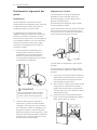
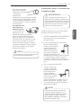
Water Line Installation Instructions
Install the shutoff valve on the nearest
frequently used drinking water line.
1
SHUT OFF THE MAIN WATER SUPPLY
Turn on the nearest faucet to relieve the
pressure on the line.
2
CHOOSE THE VALVE LOCATION
Choose a location for
the valve that is easily
accessible. It is best to
connect into the side of a
vertical water pipe. When
it is necessary to connect
into a horizontal water
pipe, make the connection to the top or
side, rather than at the bottom, to avoid
drawing off any sediment from the water
pipe.
3
DRILL THE HOLE FOR THE VALVE
Drill a ¼ in. hole in
the water pipe using
a sharp bit. Remove
any burrs resulting
from drilling the hole
in the pipe. Be careful
not to allow water
to drain into the drill. Failure to drill a ¼ in.
hole may result in reduced ice production
or smaller cubes.
WARNING
When using any electrical device
(such as a power drill) during
installation, be sure the device is
battery powered, double insulated
or grounded in a manner that will
prevent the hazard of electric shock.

19 INSTALLATION
NOTE
Be sure there is sufficient extra tubing
(about 8 feet coiled into 3 turns of
about 10 in. diameter) to allow the
refrigerator to move out from the wall
after installation.
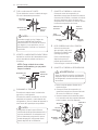
4
FASTEN THE SHUTOFF VALVE
Fasten the shutoff valve to the cold water
pipe with the pipe clamp.
Pipe Clamp
Saddle-Type
Shutoff Valve
Vertical Cold
Water Pipe
NOTE
Commonwealth of Massachusetts
Plumbing Codes 248CMR shall be
adhered to. Saddle valves are illegal
and their use is not permitted in
Massachusetts. Consult with your
licensed plumber.
5
TIGHTEN THE PIPE CLAMP
Tighten the clamp screws until the sealing
washer begins to swell.
NOTE: Do not overtighten the clamp
or you may crush the tubing.
6
ROUTE THE TUBING
Route the tubing between the cold water
line and the refrigerator.
Route the tubing through a hole drilled in
the wall or floor (behind the refrigerator or
adjacent base cabinet) as close to the wall
as possible.
Pipe Clamp
Clamp Screw
Washer
Inlet End
WARNING
Before making the connection to the
refrigerator, be sure that the refrigerator
power cord is not plugged into the wall
outlet.
7
CONNECT THE TUBING TO THE VALVE
Place the compression nut and ferrule (sleeve)
for copper tubing onto the end of the tubing
and connect it to the shutoff valve. Make
sure the tubing is fully inserted into the valve.
Tighten the compression nut securely.
8
FLUSH OUT THE TUBING
Turn the main water supply on and flush out
the tubing until the water is clear.
Shut the water off at the
water valve after about
one quart of water has
been flushed through the
tubing.
9
CONNECT THE TUBING TO THE
REFRIGERATOR
a. Remove the plastic flexible cap from the
water valve.
b. Place the compression nut and ferrule
(sleeve) onto the end of the tubing as
shown.
c. Insert the end of the copper tubing into
the connection as far as possible. While
holding the tubing, tighten the fitting.
Tubing Clamp
¼ in. Tubing
¼ in.
Compression
Nut
Refrigerator
Connection
Ferrule
(sleeve)
Saddle-Type
Shutoff Valve
Packing Nut
Outlet Valve
Compression
Nut
Ferrule (sleeve)

INSTALLATION 20
ENGLISH
10
TURN THE WATER ON AT THE SHUTOFF
VALVE
Tighten any connections that leak.
11
PLUG IN THE REFRIGERATOR
Arrange the coil of tubing so that it
does not vibrate against the back of the
refrigerator or against the wall. Push the
refrigerator back to the wall.
12
START THE ICEMAKER
Turn the icemaker on at the control panel.
The icemaker will not begin to operate
until it reaches its operating temperature
of 15°F (–9°C) or below. It will then begin
operation automatically if the icemaker has
been turned on.
Turning On the Power
1
Plug in the refrigerator.
CAUTION
Check to see if leaks occur at the water
line connections.
CAUTION
Connect to a rated power outlet.
y
Have a certified electrician check
y
the wall outlet and wiring for proper
grounding.
Do not damage or cut off the ground
y
terminal of the power plug.
La page est en cours de chargement...
La page est en cours de chargement...
La page est en cours de chargement...
La page est en cours de chargement...
La page est en cours de chargement...
La page est en cours de chargement...
La page est en cours de chargement...
La page est en cours de chargement...
La page est en cours de chargement...
La page est en cours de chargement...
La page est en cours de chargement...
La page est en cours de chargement...
La page est en cours de chargement...
La page est en cours de chargement...
La page est en cours de chargement...
La page est en cours de chargement...
La page est en cours de chargement...
La page est en cours de chargement...
La page est en cours de chargement...
La page est en cours de chargement...
La page est en cours de chargement...
La page est en cours de chargement...
La page est en cours de chargement...
La page est en cours de chargement...
La page est en cours de chargement...
La page est en cours de chargement...
La page est en cours de chargement...
La page est en cours de chargement...
La page est en cours de chargement...
La page est en cours de chargement...
La page est en cours de chargement...
La page est en cours de chargement...
La page est en cours de chargement...
La page est en cours de chargement...
La page est en cours de chargement...
La page est en cours de chargement...
La page est en cours de chargement...
La page est en cours de chargement...
La page est en cours de chargement...
La page est en cours de chargement...
La page est en cours de chargement...
La page est en cours de chargement...
La page est en cours de chargement...
La page est en cours de chargement...
La page est en cours de chargement...
La page est en cours de chargement...
La page est en cours de chargement...
La page est en cours de chargement...
-
 1
1
-
 2
2
-
 3
3
-
 4
4
-
 5
5
-
 6
6
-
 7
7
-
 8
8
-
 9
9
-
 10
10
-
 11
11
-
 12
12
-
 13
13
-
 14
14
-
 15
15
-
 16
16
-
 17
17
-
 18
18
-
 19
19
-
 20
20
-
 21
21
-
 22
22
-
 23
23
-
 24
24
-
 25
25
-
 26
26
-
 27
27
-
 28
28
-
 29
29
-
 30
30
-
 31
31
-
 32
32
-
 33
33
-
 34
34
-
 35
35
-
 36
36
-
 37
37
-
 38
38
-
 39
39
-
 40
40
-
 41
41
-
 42
42
-
 43
43
-
 44
44
-
 45
45
-
 46
46
-
 47
47
-
 48
48
-
 49
49
-
 50
50
-
 51
51
-
 52
52
-
 53
53
-
 54
54
-
 55
55
-
 56
56
-
 57
57
-
 58
58
-
 59
59
-
 60
60
-
 61
61
-
 62
62
-
 63
63
-
 64
64
-
 65
65
-
 66
66
-
 67
67
-
 68
68


Signature UPFXC2466S Le manuel du propriétaire
- Catégorie
- Frigos
- Taper
- Le manuel du propriétaire
dans d''autres langues
Autres documents
-
 Prime-Line D 1522 Mode d'emploi
-
LG LFCS31626S Le manuel du propriétaire
-
LG LFX33975ST Le manuel du propriétaire
-
LG LFX31945ST Le manuel du propriétaire
-
LG LFXC24726S Le manuel du propriétaire
-
LG LFXS30726S Le manuel du propriétaire
-
LG LFX31935ST Le manuel du propriétaire
-
LG LFXS30766S Le manuel du propriétaire
-
LG LFX25991ST Le manuel du propriétaire
-
LG LMXS28626S Le manuel du propriétaire
