Dometic Aircommand Heron 2.2 Guide d'installation
- Taper
- Guide d'installation

• InstallationInstructions
• CommissioningofHERON2.2afterinstallation
• Possiblefaultsandremedy
• Specications
• WarrantyConditions
• Noticed’installation
• Miseenserviced’IBISaprèsl’installation
• Défautséventuelsetsolutions
• Spécications
• Conditionsdegarantie
• Einbauanleitung
• InbetriebnahmedesIBISnachdemEinbau
• MöglicheProblemeundihreBehebung
• Spezikationen
• Garantiebedingungen
• InstruccionesdeInstalación
• PuestaenMarchadelIBISdespuésdesuinstalación
• Posiblesfallosysoluciones
• Especicaciones
• CondicionesdelaGarantía
Pantone Cool Grey 9U
Pantone 301 U
Pantone DS196 - 4 U (Alternative)
HERON 2.2
AIRCONDITIONER
OWNER’S MANUAL

WARRANTY OF REFRIGERATED AIRCONDITIONING
Warranty within Australia
We undertake by this warranty to rectify, free of charge, at our nearest authorised service agent, any fault due to faulty workmanship or replacement of any faulty components
within 12 months from the date of the rst retail purchase thereof. This undertaking is conditional upon the appliance being installed and operated in accordance with
our instructions, and does not apply to consumable components such as filters, or to adjustments necessary due to misuse of airconditioner. Normal user maintenance,
setting of controls and transit damage are also excluded. No other person, firm or corporation is authorised by us to offer or give on our behalf any other or greater warranty
than that given by us under this warranty. The benefits conferred by this warranty are in favour of the original retail purchaser and any other person deriving title to the
goods through or under such person and are intended to be separate from the additional to all other rights and remedies which they may have in law in respect of the goods.
1. In the event that warranty service is required, the purchaser must contact Aircommand Australia for service approval.
Contact information: phone 08 8445 2877, fax 08 8243 0628, or email sales@aircommand.com.au
2. Warranty repairs will only to be carried out by the manufacturer’s authorised service repairer.
3. It is the purchaser’s responsibility to deliver unit to the manufacturer’s nearest authorised Service Centre.
The manufacturer will not bear any costs involved in Service Agent’s travelling expenses or delivery charges.
Warranty outside Australia
1. Aircommand products are covered by 12 months warranty from date of first retail purchase.
2. For warranty enquiries outside Australia, please contact your national supplier .
* The warranty card must be completed and returned to the manufacturer for registration, or to the distributor in country of purchase. Online
warranty registration is available at www.aircommand.com.au/registration.html
GARANTIE FÜR KLIMAGERÄT MIT KÜHLFUNKTION
Garantie innerhalb Australiens
Wir verpflichten uns mit dieser Garantie, innerhalb von 12 Monaten ab Datum des ersten Einzelhandelskaufs, über unseren nächsten Vertragshändler jeden
durch fehlerhafte Verarbeitung entstandenen Defekt kostenlos zu beheben oder alle defekten Teile kostenlos auszutauschen. Diese Verpflichtung gilt unter
dem Vorbehalt, dass das Gerät im Einklang mit unseren Anleitungen installiert und betrieben wird, und gilt nicht für Verschleißteile wie z.B. Filter oder für
Korrekturarbeiten, die durch den Missbrauch des Klimageräts bedingt sind. Normale Wartung durch den Benutzer, die Einstellung der Bedienelemente und
Transportschäden sind ebenfalls ausgeschlossen. Wir haben keine anderen Personen, Firmen oder Unternehmen bevollmächtigt, in unserem Namen irgendeine
andere oder weiter reichende Garantie anzubieten oder zu geben als die von uns im Rahmen dieser Garantie erteilte. Die mittels dieser Garantie gewährten
Leistungen gelten zu Gunsten des ursprünglichen Einzelhandelskäufers oder jeder anderen Person, die ihren Anspruch auf die Waren durch oder von dieser Person
ableitet, und sind dazu gedacht, getrennt von allen zusätzlichen Rechten und Behelfen zu gelten, die ihnen kraft Gesetzes hinsichtlich dieser Waren zustehen..
1. Für den Fall, dass eine Garantieleistung erforderlich wird, muss sich der Käufer mit Aircommand Australia zur Genehmigung der
Leistung in Verbindung setzen. Kontaktinfo: Tel. 08 8445 2877, Fax: 08 8243 0628 oder E-Mail: [email protected]
2. Unter die Garantie fallende Reparaturen werden nur durch den Vertragsreparaturdienst des Herstellers ausgeführt.
3. Die Lieferung des Geräts an das nächstliegende Service Centre des Herstellers ist Aufgabe des Käufers.
Der Hersteller deckt keine der durch die Anfahrtskosten des Vertragsdienstes oder Lieferkosten entstandenen Ausgaben.
Garantie außerhalb Australiens
1. Für die Produkte von Aircommand gilt eine 12-monatige Garantie ab Datum des ersten Einzelhandelskaufs.
2. Für Garantieanfragen außerhalb Australiens wenden Sie sich bitte an Ihren inländischen Händler.
* Die Garantiekarte ist auszufüllen und dem Hersteller, bzw. dem Vertriebshändler im Einkaufsland, zur Registrierung zuzuschicken. Die Garantie kann online unter der
folgenden Adresse registriert werden: www.aircommand.com.au/registration.html
GARANTIE DE CLIMATISATION RÉFRIGÉRÉE
Garantie pour l’Australie
Nous nous engageons par cette garantie à faire rectifier gratuitement par notre agent de service tout défaut résultant d’un défaut de fabrication ou de remplacer tout
composant défectueux dans les 12 mois suivant la date du premier achat de l’appareil au détail. Cet engagement est conditionnel à l’installation et à l’exploitation
de l’appareil conformément à nos instructions, et ne s’applique pas aux composants consommables tels que les filtres, ou à un réglage attribuable à la mauvaise
utilisation du climatiseur. L’entretien, les réglages des commandes et les dommages en transit sont également exclus. Aucune autre personne, firme ou entreprise n’est
autorisée par nous à offrir ou à donner en notre nom toute autre garantie ou une garantie supérieure à celle donnée par nous en vertu de cette garantie. Les avantages
conférés par cette garantie reviennent à l’acquéreur au détail original ou à toute autre personne qui deviendra propriétaire de l’appareil par le biais de cette personne
ou avec son autorisation et sont censés être supplémentaires à tous les autres droits et recours dont il pourra disposer légalement en ce qui concerne l’appareil.
1. Au cas où un service de garantie serait nécessaire, l’acquéreur doit contacter Aircommand Australia pour obtenir une autorisation de service.
Cordonnées: téléphone 08 8445 2877, fax 08 8243 0628, ou email sales@aircommand.com.au
2. Les réparations sous garantie seront effectuées exclusivement par le réparateur autorisé du fabricant.
3. La responsabilité incombe à l’acquéreur de livrer l’appareil au Centre de service autorisé le plus proche du fabricant.
Le fabricant ne subira pas les frais de déplacement ou de livraison de l’agent de service.
Garantie en dehors de l’Australie
1. Les produits Aircommand sont couverts par une garantie de 12 mois à compter de la date du premier achat au détail.
2. Pour toute demande de renseignements en dehors de l’Australie, veuillez contacter votre fournisseur national.
* La carte de garantie doit être remplie et renvoyée au fabricant pour être enregistrée, ou au distributeur dans le pays de l’achat. Un enregistrement de garantie en ligne est
disponible sur www.aircommand.com.au/registration.html
GARANTÍA DEL ACONDICIONADOR DE AIRE REFRIGERADO
Garantía en Australia
Nos comprometemos por medio de esta garantía a rectificar, sin cargo, en nuestra agencia de servicio autorizado, cualquier fallo causado por un componente
defectuoso dentro de los 12 meses contados a partir de la primera fecha de compra. Este compromiso es condicional a que el aparato haya sido instalado y
operado de acuerdo con nuestras instrucciones y no cubre componentes de consumo tales como filtros, o cualquier ajuste necesario debido al uso incorrecto del
acondicionador de aire. Se excluyen también las tareas de mantenimiento normales, el ajuste de los controles y cualquier daño ocurrido durante su transporte.
Ninguna otra persona, firma o corporación está autorizada a ofrecer o dar en nuestro nombre una garantía más extensa o diferente a la otorgada por esta garantía. Los
beneficios conferidos por esta garantía son a favor del comprador original y cualquier otra persona que tenga derecho al título de la mercadería a través o bajo dicha
persona y está separada de otros derechos adicionales o soluciones a las que puedan tener derecho, según la ley, respecto a las mercaderías.
1. En el caso que se necesite hacer uso del servicio de garantía, el comprador debe ponerse en contacto con Aircommand Australia para la aprobación del
servicio. Información de contacto: Teléfono: 08 8445 2877, Fax 08 8243 0628 o Email sales@aircommand.com.au
2. Las reparaciones cubiertas por la garantía deberán ser llevadas a cabo por el servicio de reparaciones autorizado por el fabricante.
3.. La entrega de la unidad al Centro de Servicio más cercano autorizado por el fabricante es responsabilidad del comprador
El fabricante no se hará responsable de ninguno de los costes involucrados por gastos de viaje o cargos de entrega por parte del agente proveedor del
servicio
Garantía fuera de Australia
1. Los productos de Aircommand están cubiertos por 12 meses de garantía a partir de la primera fecha de compra.
2. Por cualquier información respecto a la garantía fuera de Australia, sírvase ponerse en contacto con su proveedor nacional.
* Esta tarjeta de garantía debe ser completada y enviada al fabricante para su debida registración o alternativamente al distribuidor en el país de compra. La
registración de la garantía puede hacerse también online en: www.aircommand.com.au/registration.html

CUSTOMER’S COPY
Purchaser’s Name .............................................................................................................................................................................................................................
Address ................................................................................................................................................................................................................................................
............................................................. P/Code .......................................... Phone ............................................ Email ............................................................
Purchase Date ........................................................................................... Installed on .............................................................................................................
Model ........................................................................................................... Serial Number ........................................................................................................
Purchased From ................................................................................................................................................................................................................................
Address ................................................................................................................................................................................................................................................
............................................................. P/Code .......................................... Phone ............................................ Email ............................................................
COPIE DU CLIENT
Nom de l’acquéreur .........................................................................................................................................................................................................................
Adresse ................................................................................................................................................................................................................................................
............................................................. Code postal ................................. Téléphone .................................... Email ............................................................
Date de l’achat .......................................................................................... Installé le .................................................................................................................
Modèle ........................................................................................................ Numéro de série ....................................................................................................
Acheté chez ........................................................................................................................................................................................................................................
Adresse ................................................................................................................................................................................................................................................
............................................................. Code postal ................................ Téléphone ................................... Email ............................................................
KOPIE FÜR DEN KÄUFER
Name des Käufers ............................................................................................................................................................................................................................
Anschrift ..............................................................................................................................................................................................................................................
............................................................. PLZ ................................................. Telefon .......................................... Email .............................................................
Kaufdatum ................................................................................................. Einbaudatum ..........................................................................................................
Modell ......................................................................................................... Seriennummer .......................................................................................................
Gekauft bei .........................................................................................................................................................................................................................................
Anschrift ..............................................................................................................................................................................................................................................
............................................................. PLZ ................................................. Telefon ........................................... Email ............................................................
COPIA PARA EL CLIENTE
Nombre del Comprador ................................................................................................................................................................................................................
Dirección .............................................................................................................................................................................................................................................
............................................................. Código Postal ............................. Teléfono ........................................ Email ............................................................
Fecha de compra .................................................................................... Fecha de instalación ............................................................................................
Modelo ........................................................................................................ Número de Serie ...................................................................................................
Comprado en .....................................................................................................................................................................................................................................
Dirección .............................................................................................................................................................................................................................................
............................................................. Código Postal ............................. Teléfono ........................................ Email ............................................................

INSTALLATION INSTRUCTIONS FOR HERON 2.2
The Heron 2.2 is suitable for installation in most caravans & motorhomes. Installation in Commercial and
Industrial vehicles and equipment should be referred to AIRCOMMAND AUST for assessment of
suitability. The Heron System must be installed in accordance with national wiring regulations.
The capacity of the airconditioner to adequately cool or heat a van, is dependent on:
• The size of the van or vehicle.
• The thickness and quality of thermal insulation installed in the van.
• The expected outside or ambient conditions.
The Heron 2.2 is recommended for vans up to 5.2 m overall, but
assumes that wall and ceilings are insulated with a minimum of
25 mm of insulation, wool or foam. The Heron 2.2 may be used
in vans up to 7 metre provided the insulation is a minimum
38mm thick and all windows are double insulated. Windows
should all have shades or curtains as a minimum.
If the van is to be used mainly in extreme conditions (40°C plus),
then be conservative, i.e. ensure the best insulation is installed,
consider double glazed windows, and size the airconditioner
down to 4.8 m maximum.
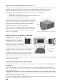
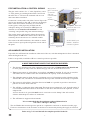
DESCRIPTION OF THE HERON 2.2 SYSTEM
The HERON 2.2 is a split system,
utilizing a condenser set (referred to
throughout this text as a CON/SET)
and an airhandler
(referred to as an A/H).
The Con/set is designed for installation
beneath a bunk, settee, or in the bottom
of a floor cupboard. Refer fig. 1 for dimensions.
The A/H is designed for fitment into an overhead cupboard
or similar, and comes complete with facia and controls.
See fig. 2.
The A/H and CON/SET are coupled by means of a pair of
refrigerant lines, and a control cable. The pipework is not
supplied with the unit, but a standard 7 m control cable is.
Before proceeding with the installation, consider a number of important details that must be complied with
in the following description.
CHOOSING A POSITION FOR THE CON/SET
Generally, avoid installation on the left hand side (awning side), as the condenser set will discharge hot air
into this space.
Australia & UK (LHS of road) it is usual to install the con/set on the right hand side, either under a bunk,
settee or at the bottom of a floor cupboard. Conversly, continental Europe (RHS of road) the con/set should
be on the left hand side.
NOTE: Ensure that wherever the con/set is installed, reasonable access to the top of the unit is always
available, for service, and any shelving etc. above, must be easily removed. Also, the two line valves on the
back of the unit must be easily accessed.
The maximum length of pipework between the Con/set and the A/H is 5 metres. Installations exceeding this
may require extra refrigerant to be added to the system.
1
Figure 1 External dimensions of condenser
Figure 2 External
dimensions of air
handler
489
286
385
454
282
239
249
7
28
286
19
105
155
136

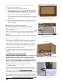
INSTALLING THE CONDENSER SET
■
Marking out the floor
Use the floor template as provided (or refer to fig. 3). Both, or either end of the con/set may be hard against
a wall or panel, but the back of the unit must have sufficient clearance to allow easy access to the line
valves (see fig. 4). Once a convenient position has been decided upon, place the template, side marked
“Inside Wall”, hard against the inside skin of the van, and mark out the six 114 mm diameter (4
1/2”)
condenser air inlet holes, and the square compressor well hole (see fig. 3).
Note: Check to see if any structural floor members will interfere with any of these holes. It is essential that
the compressor well is unimpeded. The compressor feet project through the well by 4 to 5 mm, therefore
clearance of at least 8 mm must be maintained between the well and any floor members. Eg. Angles or
tubes. Lack of clearance will result in noise and vibration. See fig 5.
2
372
237
107
390
265
180
50
10
178
Comp.
well
Normally install condenser
set opposite to annexe
Figure 3
Figure 4
Figure 5
Cut out detail for
condenser
Line
Valves
Clips
Figure 4a
Showing method for securing condenser set to floor with 3 clips
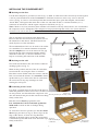
The air inlet holes will tolerate some obstruction.
However the total area must not be less than 75% of
the inlet holes in the chassis. DO NOT install fine
mesh (flywire) over the inlet holes.
We recommend that a hole saw be used to cut out the
six round holes. If a structural member is beneath,
then the complete cut out can be removed. The gap
between the top of the structural member and the
underside of the unit (i.e. the floor thickness) will
help in overcoming the restriction of the member.
■ Marking out the wall
Now mark out the hole in the wall for the condenser
discharge grille (see fig. 5).
Mark out the position and size of the air outlet hole,
from inside the van, using the floor as reference.
Pilot holes can be drilled at the four corners, and the
hole cut out from the outside. It is essential to frame
up this hole to give a firm seal to the air outlet from
the con/set and to stop any discharge air from
entering the wall space.
■ Positioning of the Con/set
Lay down a generous bead of silicone on the floor to
match the perimeter of the Con/set. Now, lift the Con/
set into position, and check that the compressor well
does not interfere and prevent the con/set from sitting
firmly on the floor.
Push the Con/set hard up against the wall.
It is vital that the Con/set seals hard against the
inside wall to ensure no hot air leakage during
operation.
To secure the Con/set in position, use the three hold
down clips provided (see fig. 4). These clip over the
edge of the chassis. At least one clip should be
installed on the back edge to ensure the good airseal
is maintained against the inside wall. Screw the clips
firmly to the floor.
Foot print
of condenser

PIPE INSTALLATION & CONTROL WIRING
The pipe work consists of a
1
/4” tube (liquid line), and a
3
/8” tube (return gas) running between the Con/set and
the A/H. The
3
/8” line must be insulated with 10 x 10
mm foam rubber insulation.
Connection is made at the side of the Con/set. Pipe work
may be run internally to the A/H, or may be run through
holes in the floor and run externally to a convenient
re-entry point, or the pipes may be built into the
wallspace during van construction. NB. Pipework
installed in walls must be well insulated to avoid
“sweating” and possible long term moisture damage.
The control wiring will normally follow the pipework
and be taped to it. NB. If the control cable is to be run
externally, then it must be run in a suitable conduit.
Now refer to the A/H installation, after which we return
to the Con/set to open up the refrigeration circuit and fit
the panel.
AIR HANDLER INSTALLATION
If possible, the A/H should be installed at either end of the van, such that unimpeded air flow is obtained
down the length of the van.
If this is not possible, install the A/H in as central a position as possible.
6 MOST IMPORTANT POINTS THAT MUST BE SATISFIED
1. The distance from the back of the cupboard to the back of the A/H must not be less than 90 mm
to allow proper air entry to the fan. Insufficient gap will also increase the noise level.
2. Two separate return air grilles/filters are supplied, and must be installed. If only one is used, this
will reduce the air volume back to the fan and hence the capacity of the airconditioner.
3. The airhandler must be fitted allowing a minimum space of 25 mm between the right hand of the
A/H and the wall, and likewise 25 mm between the top of the A/H and the inside top of cupboard.
4. The return air grilles/filters, should be fitted as far back as is possible to provide a more direct
path for air to flow back to the fan.
5. The A/H has a condensate drain underneath. This drain must continuously “fall” from the outlet. It
is recommended that the bottom of the A/H be 75 mm above the bottom of the cupboard, to allow
adequate fall.
A lesser amount is ok, provided much care is exercised to avoid “humps” that will result in
airlocks and backup & overflow of condensate.
6. The A/H must be supported from beneath.
It is recommended that the minimum cupboard dimensions be
525 wide x 340 high x 340 deep.
The Air Handler has been designed to operate in a cupboard or enclosure as described on this page.
Under no circumstances is the resistance to airflow to be increased by ducting the supply or return air.
Refer to fig. 7 & 8 and the full size template provided in the kit
3
Figure 6a
Figure 6Refrigeration
pipes cross back
of enclosure
and come
round on LHS
to give
flexibility
Refrig lines, drain hose
electrical cable cover
with moulding
2 return air
filter assy.
inset to
bottom of
cupboard.
Section detail of air
handler - minimum
clearance required
Support

Figure 8 Minimum space required
on LHS of air handler
4
Mark out the A/H cut out as per fig. 7. Ensure the choice of
location satisfies the following:
A. The Facia panel will be centrally located.
B. The right hand edge of the cutout is a minimum of 50 mm
from right hand end of the cupboard. This will ensure that
when the A/H is installed, a minimum space of 25 mm exists
down the side of the A/H, as requested on page 3.
C. The left hand side of the A/H must be a minimum of 110 mm
from the LHS of the cupboard to allow pipes to be connected.
(Refer fig. 8)
D. The bottom of the cutout should be at least 75 mm above the
bottom of cupboard to allow the condensate drain to “fall”
away sufficiently.
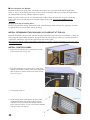
■ Fitting of the 2 return air grilles/filters
Provided the cupboard is 525 mm wide or more, the two
grilles can be installed side by side in the underside of the
cupboard. (Refer fig. 9)
In the case of pop top vans, it may be convenient to install one of
the two through the top. Make sure however, that both are
installed.
Place the grilles as far back as is possible to allow the most direct
route of the air to the fan inlet.
Cut out size for each grille is 158 x 232.
The following describes the procedure for both a cupboard with a
removable front, and a cupboard with a front that is not easily
disassembled. Typically the latter type will have 4 to 5 mm ply
which will need reinforcing around the perimeter of the cutout
and tying to the main structural members of the cupboard assy.
Cut rectangular hole as detailed in fig. 7.
Use adhesive tape to stick down the template. Drill holes at the
corners of the cutout to allow a jig saw to cut out the entire
cutaway.
It is important to cut the hole out accurately.
If the front panel is a solid 19 mm panel, the A/H will not need
additional support. If however the front panel is light ply,
then this must be strengthened after cutting out as per the
template. This framing should be 20 mm thick to provide the
necessary support, and should tie in with the main cupboard
members, to support the weight of the Airhandler.
■ Installation of the refrigeration pipe work and
condensate drain
The 9.5 mm Ø and the 6.4 Ø pipes can enter either side of the
cupboard, and be carefully manipulated to make the connection to
the Airhandler. The 9.5 Ø pipe must be insulated entirely.
The condensate drain is normally run vertically. 12 mm hose or poly
pipe is preferred. Two elbows are provided in the installation kit to
change direction from the vertical run to the horizontal to connect
the airhandler. Failure to use this elbow usually results in a hump in
the drain which may impede drainage, or a kink refer fig.10
.
Figure 7 Cut out dimensions for
installation of air handler
Figure 9
Figure 10 Showing required fall
of drain line
Drain elbow
Two return air grill
cut outs 158mm x 232mm

5
■ Now Install the Air Handler
Insert the A/H into the front panel, and shift to the right as far as possible such that the right hand
flange is fully over the front panel. Now insert a screw to hold the A/H in place while the copper tubes
are manipulated to line up with the respective nipples.
Mark any excess tube to be cut off, and remove the A/H to allow the flare nuts to be put on and the
flares made. Unscrew both flare nuts from the nipples of the A/H, ensuring the sealing caps are
removed.
See page 6 for tips on making flares.
Having completed the flaring, reinstall the A/H, remembering to shift it fully to the right after insertion.
Couple the flare nut connections and do up firmly.
INSTALL BITUMINOUS TAPE AROUND 9.5 FLARE NUT AT THE A/H.
From the Installation kit provided, take the length of bituminous tape and wrap it around the
3
/8 flare nut
and joining the foam rubber insulation already on the pipe. The purpose of this is to avoid formation of
condensate, which may drip into the cupboard. Install control plate.
Never ever use thread sealing compounds on the flare as possible system contamination can occur and a
blockage may result.
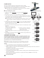
INSTALL CONTROL PANEL.
1. Plug service lead into power point but leave the
power turned off (see fig 14)
2. Plug the condenser set control cable (3 pin plug)
and the Air Handler control cable (8 pin plug) into
their respective sockets at the back of the switch
box (see fig 15).
3. Turn power point on.
4. Push control panel flush against the face of the
cupboard and then slide to the right to engage
with the fascia panel. Hold the control panel in
place with two screws. Cover screw heads with the
caps provided. (see fig 16)
Figure 14
Figure 15
Figure 16

POWER SUPPLY
The unit is designed to plug into a normal mains electricity supply.
This plug must be accessible after installation. If a new plug is installed, then it
must be positioned near to the airhandler and be easily accessible.
Note:
The supply cord is designated Type F. If replacement is necessary it should be
replaced by an Aircommand approved technician.
■ Tips on Making Flare Joints
1. Always use a proper Tube Cutter to cut tube to length (Never Ever a
Hacksaw).
2. Remember to put the flare nut on the tube prior to making flare.
3. Always deburr the inside of the tube. Buy a proper deburring tool to do this. It
is a good idea to wipe around the inside of the tube to wipe away any copper
particles that may have come off during deburring.
NB.
If an inside burr is left on, the flaring head will inevitably drive this burr onto the
surface of the flare, resulting in a pitted flare face, which will almost certainly
leak.
4. Clamp the tube in the flaring block firmly. For 1/4” tube (6.4Ø), the unflared
tube should protrude 1.0 mm. For 3/8” tube (9.5Ø) the unflared tube should
protrude 1.5 mm. See Fig. I, J & K
5. The flaring head should be lubricated with a smear of oil. (Preferably vacuum
pump oil).
Tighten down flaring head by:
a) Contact tube with flare head
b) Advance 3/4 turn
c) Back off 1/4 turn
d) Advance 3/4 turn etc, until flare
has bottomed in the anvil (don’t
tighten on the bottom).
This oscillating manner will ensure an accurate contour and guard against
splitting.
6. Check that the resulting flare shows a bright continuous ring around the face,
and no imperfections exist.
CHARGING THE SYSTEM
The system is charged with R22 or R407C as marked in Austrualia / New
Zealand or R407C in Europe, which is a prescribed refrigerant gas. Most
states / countries will require the installer to have an appropriate license.
The condenser set is factory precharged, but the Air handler and connecting
pipework needs to be evacuated of noncondensables.
Please note: In Australia, state/country laws re the handling of prescribed
refrigerants may prohibit the purging method. Such laws take precedence.
6
Figure J
H
H
1
3
For 6.4¯ Tube,
1/3 H = 1 mm
For 9.5¯ Tube,
1/3 H = 1.5 mm
Figure K
A
B
D
E
C
FLARED FITTINGS
A. Correctly made flare
B. Flare too small
C. Flare too large
E. Flare has burrs on edge
D. Flare is uneven
Figure I: Prefered flaring
tool ratchet/eccentric type
Method
• Use a vacuum pump to remove noncondensables from A/H & pipework.
• Tighten all flare nut connections on both the Con/set and the A/H.
• Remove schrader valve caps and connect manifold gauge hoses, preferably to both valves (make sure
valve depressors are set ok).
• If both hoses are fitted, then evacuate for 10 minutes.
• If only one, then evacuate for 15 mins.
• Check that the pump maintains a high vacuum by isolating systems with manifold gauge taps and
observing suction gauge.
• Remove both stem caps, then isolate the vac. pump, before turning on both valve stems. Fully
backseat both, and refit caps.
• Now check for leaks.

LEAK TESTING
It is of the utmost importance that a leak check is made on the 4 flare nut connections. A leak,
however small, will result in the aircon system losing capacity and endanger the compressor.
1. Use either soapy water, or a proprietary leak test solution.
Paint on each flare nut (particularly the neck) and inspect carefully for any telltale bubbles. Use a torch
to improve visibility, particularly in the A/H area.
Any leak will generally be remedied by further tightening of the flare nut. In the event of a faulty flare,
the line valves must be turned off, the A/H pumped out, and the flare remade.
2. Use an ELECTRONIC leak detector - preferred.
Test initially on low sensitivity, examining in particular the neck of each flare nut. Increase the
sensitivity until you are confident that no leak exists.
TEST TO BE CARRIED OUT BY INSTALLER PRIOR TO DELIVERY
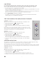
COOLING: (ref fig.17)
NB. The unit will not run on cooling if the inside temp. is much below 18°C.
1. Turn fan speed selector to (Hi Speed Cooling)
2. Turn mode selector to (Cooling)
3. Adjust the thermostat counter clockwise until the condenser set is heard to
start.
Ensure that cold air is being discharged, and there are no pipe rattles etc. After
about 15 minutes of running, and providing the inside temp. is above 20°C, then
the discharge air should be 12°C or cooler than the return air.
HEATING: (ref fig.17)
NB. The unit will not heat if inside temp. is much above 28°C.
1. Turn fan speed selector to (Heating Speed)
2. Turn mode selector to (Heating)
3. Adjust the thermostat to max. clockwise position.
There will be approximately 30 seconds delay before heating is apparent.
4. After about 15 mins. the discharge air will be approx. 25°C more than the
return air.
OPERATING INSTRUCTIONS
This appliance is not intended for use by young children or infirm persons without supervision. Young
children should be supervised to ensure that they do not play with this appliance.
This airconditioner may be used in cooling mode with outside temperatures from 18ºC to 48ºC, and inside
temperatures from 18ºC to 30ºC. In heating mode, the airconditioner may be used with outside and inside
temperatures up to 30ºC.
COOLING: (ref fig.17)
NB. The unit will not run on cooling if the inside temp. is much below 18°C.
1. Turn fan speed selector to (Hi Speed Cooling)
2. Turn mode selector to (Cooling)
3. Adjust the thermostat counter clockwise until the condenser set is heard to start.
4. Gradually over time, adjust the thermostat until comfortable conditions are maintained.
7
Figure 17

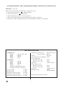
UNIT SPECIFICATIONS
Condenser set:
Height - 250 mm Above floor
Width - 465 mm
Depth - 440 mm
Weight - 30 kg
Air Handler:
Height - 240 mm
Width - 385 mm
Depth - 250 mm
Weight - 4 kg
Minimum cupboard dimensions:
320 high x 525 wide x 340 deep
Cooling output: 2.2 KW
Heating output: 1.5 KW
Maximum current (cooling): 4.0 amps
Maximum current (heating): 6.5 amps
Maximum locked rotor current: 19 amps
Refrigerant: Australia only R22 or 407C
as marked
Euro production R407C
Charge: 700 grms.
Air volume (max) Air Handler: 110 l/s
Fan (Air handler):
Resistance run wdg.: 165Ω
Resistance aux wdg.: 265Ω
Capacitor: 1.5 mfd. 440 vac
Fan (Condenser set):
Resistance run wdg.: 168Ω
Resistance aux wdg.: 150Ω
Capacitor: 2.5 mfd. 440 vac
Heating element: 1500W
(Pt. No. 4002024)
Refer fitting instructions included
8
AVOID RESTARTING THE COMPRESSOR WITHIN 3 MINUTES OF TURNING OFF
HEATING: (ref fig.16)
NB. The unit will not heat if inside temp. is much above 28°C.
1. Turn fan speed selector to (Heating Speed)
2. Turn mode selector to (Heating)
3. Adjust the thermostat to max. clockwise position.
There will be approximately 30 seconds delay before heating is apparent.
4. Gradually over time, adjust the thermostat until comfortable conditions are maintained.

9

10
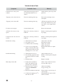
Condenser set is noisy and
vibrates
“Tipping” noise from Con/set
“Tipping” noise from A/H
Unit does not energize
A/H fan will not run on any
speed
Compressor & cond. fan will
not run
Insufficient cooling
Insufficient heating
Water drips from A/H
TROUBLE SHOOTING
Check that general pipework is
not touching cabinet, lid, or
chassis
Fan rotor touching inlet ring
Fan rotor touching inlet ring
Circuit breaker open
Plug not in correctly at back of
S/W box
Plug not in correctly at back of
S/W box
1. Thermostat set too high
2. Fan speed too low
3. Condenser fan not running
4. Unit is low on refrigerant
charge. Generally the temp.
diff. between return air and
discharge air is 11 to 12°C
1. Thermostat set too low
2. If no heating apparent check
8 pin plug at back of switch
box
3. Element faulty
1. Faulty drain installation,
elbow into A/H must not
protrude above grommet
2. Drain hose does not have
continuous downward
gradient
3. Drain hose kinked or blocked
4. Condensate dripping off
3
/8
flare nut on A/H
Gently bend or pull away from
panel etc
Ease motor retaining screws,
and adjust
A/H must be partially removed
from cupb’d. Remove top and
adj. fan ht. via 4 support bolts
(5/16”)
Reset circuit breaker
Remove control panel & push in
8 pin plug
Remove control panel & push in
3 pin plug
Adjust more into blue
Switch fan to high
Check free to turn
Check resistor ok
Refrigeration Mech. to adjust
charge
Adjust further into red
Remove control panel and push
in plug
Replace element
Check correct elbow has been
used at A/H see pp. 4
Adjust accordingly
see pp. 4 & fig. 10
Ensure elbow is used at top of
vertical drop.
Wrap bituminous tape around
f/nut to insulate
Symptom Probable Cause Remedy

Please send to:
AIRCOMMAND AUSTRALIA PTY LTD
954 Port Road, Albert Park
South Australia 5014
AUSTRALIA
Envoyer à:
AIRCOMMAND AUSTRALIA PTY LTD
954 Port Road, Albert Park
South Australia 5014
AUSTRALIA
Bitte einschicken an:
AIRCOMMAND AUSTRALIA PTY LTD
954 Port Road, Albert Park
South Australia 5014
AUSTRALIA
Por favor, sírvase enviar a:
AIRCOMMAND AUSTRALIA PTY LTD
954 Port Road, Albert Park
South Australia 5014
AUSTRALIA
Pantone Cool Grey 9U
Pantone 301 U
Pantone DS196 - 4 U (Alternative)
Pantone Cool Grey 9U
Pantone 301 U
Pantone DS196 - 4 U (Alternative)
Pantone Cool Grey 9U
Pantone 301 U
Pantone DS196 - 4 U (Alternative)
Pantone Cool Grey 9U
Pantone 301 U
Pantone DS196 - 4 U (Alternative)

MANUFACTURER’S COPY
Purchaser’s Name .............................................................................................................................................................................................................................
Address ................................................................................................................................................................................................................................................
............................................................. P/Code .......................................... Phone ............................................ Email ............................................................
Purchase Date ........................................................................................... Installed on .............................................................................................................
Model ........................................................................................................... Serial Number ........................................................................................................
Purchased From ................................................................................................................................................................................................................................
Address ................................................................................................................................................................................................................................................
............................................................. P/Code .......................................... Phone ............................................ Email ............................................................
COPIE DU FABRICANT
Nom de l’acquéreur .........................................................................................................................................................................................................................
Adresse ................................................................................................................................................................................................................................................
............................................................. Code postal ................................. Téléphone .................................... Email ............................................................
Date de l’achat .......................................................................................... Installé le .................................................................................................................
Modèle ........................................................................................................ Numéro de série ....................................................................................................
Acheté chez ........................................................................................................................................................................................................................................
Adresse ................................................................................................................................................................................................................................................
............................................................. Code postal ................................. Téléphone .................................... Email ............................................................
KOPIE FÜR DEN HERSTELLER
Name des Käufers ............................................................................................................................................................................................................................
Anschrift ..............................................................................................................................................................................................................................................
............................................................. PLZ .................................................. Telefon .......................................... Email ............................................................
Kaufdatum .................................................................................................. Einbaudatum .........................................................................................................
Modell .......................................................................................................... Seriennummer ......................................................................................................
Gekauft bei .........................................................................................................................................................................................................................................
Anschrift ..............................................................................................................................................................................................................................................
............................................................. PLZ ................................................. Telefon ............................................ Email ...........................................................
COPIA PARA EL FABRICANTE
Nombre del Comprador ................................................................................................................................................................................................................
Dirección .............................................................................................................................................................................................................................................
............................................................. Código Postal ............................. Teléfono ........................................ Email ............................................................
Fecha de compra ..................................................................................... Fecha de instalación ............................................................................................
Modelo ........................................................................................................ Número de Serie ...................................................................................................
Comprado en .....................................................................................................................................................................................................................................
Dirección .............................................................................................................................................................................................................................................
............................................................. Código Postal ............................. Teléfono ........................................ Email ............................................................

AIRCOMMAND AUSTRALIA PTY LTD
954 Port Road, Albert Park
South Australia 5014
AUSTRALIA
Tel: (08) 8345 8444
Fax: (08) 8243 0628
AIRCOMMAND EUROPE
AIRVA
ZI Les Béthunes
10, Avenue du Fief
95310 ST OUEN L AUMONE
FRANCE
Tel: +33 (0) 134642333
Pantone Cool Grey 9U
Pantone 301 U
Pantone DS196 - 4 U (Alternative)
E&OE
-
 1
1
-
 2
2
-
 3
3
-
 4
4
-
 5
5
-
 6
6
-
 7
7
-
 8
8
-
 9
9
-
 10
10
-
 11
11
-
 12
12
-
 13
13
-
 14
14
-
 15
15
-
 16
16


Dometic Aircommand Heron 2.2 Guide d'installation
- Taper
- Guide d'installation
dans d''autres langues
Documents connexes
Autres documents
-
 Pfister BPH-DF1B Guide d'installation
-
GE AUH2436ZGDA Guide d'installation
-
 Aircommand IBIS ROOFTOP CARAVAN Le manuel du propriétaire
-
Value 21.99.1331-200 Fiche technique
-
-
-
Argo PW-UMR184EXH56 Manuel utilisateur
-
Sanyo SPW-UMR224EXH56 Manuel utilisateur
-
LG TPNH488TMA5.ANWBAAS Guide d'installation

