WIKA OLS-5200 tag:model:OLS-C01 tag:model:OLS-C02 tag:model:OLS-C04 tag:model:OLS-C05 tag:model:OLS-F1 Mode d'emploi
- Taper
- Mode d'emploi

DE
EN
Operating instructions
Betriebsanleitung
Mode d‘emploi
Manual de instrucciones
ES
FR
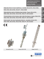
Optoelectronic level switches, models OLS-C01, OLS-C02,
OLS-C04, OLS-C05, OLS-F1, OLS-5200
Optoelektronische Füllstandsschalter, Typen OLS-C01,
OLS-C02, OLS-C04, OLS-C05, OLS-F1, OLS-5200
Commutateurs de niveau opto-électroniques, types OLS-C01,
OLS-C02, OLS-C04, OLS-C05, OLS-F1, OLS-5200
Interruptor de nivel optoelectrónico, modelos OLS-C01,
OLS-C02, OLS-C04, OLS-C05, OLS-F1, OLS-5200
Model OLS-F1Model OLS-C02Model OLS-C01

2 WIKA operating instructions models OLS-C01 ... OLS-C05, OLS-F1, OLS-5200
14235426.01 08/2017 EN/DE/FR/ES
DE
EN
ES
FR
Operating instructions models OLS-C01, OLS-C02,
OLS-C04, OLS-C05, OLS-F1, OLS-5200
Page 3 - 14
Betriebsanleitung Typen OLS-C01, OLS-C02, OLS-C04,
OLS-C05, OLS-F1, OLS-5200
Seite 15 - 26
Mode d‘emploi types OLS-C01, OLS-C02, OLS-C04,
OLS-C05, OLS-F1, OLS-5200
Page 27 - 38
Manual de instrucciones modelos OLS-C01, OLS-C02,
OLS-C04, OLS-C05, OLS-F1, OLS-5200
Página 39 - 50
© 08/2017 WIKA Alexander Wiegand SE & Co. KG
All rights reserved. / Alle Rechte vorbehalten.
WIKA
®
is a registered trademark in various countries.
WIKA
®
ist eine geschützte Marke in verschiedenen Ländern.
Prior to starting any work, read the operating instructions!
Keep for later use!
Vor Beginn aller Arbeiten Betriebsanleitung lesen!
Zum späteren Gebrauch aufbewahren!
Lire le mode d‘emploi avant de commencer toute opération !
A conserver pour une utilisation ultérieure !
¡Leer el manual de instrucciones antes de comenzar cualquier trabajo!
¡Guardar el manual para una eventual consulta!

14235426.01 08/2017 EN/DE/FR/ES
WIKA operating instructions models OLS-C01 ... OLS-C05, OLS-F1, OLS-5200 3
EN
Contents
Contents
Declarations of conformity can be found online at www.wika.com.
1. General information 4
2. Design and function 4
3. Safety 6
4. Transport, packaging and storage 9
5. Commissioning, operation 10
6. Faults 11
7. Maintenance and cleaning 12
8. Dismounting, return and disposal 12
9. Specifications 13

14235426.01 08/2017 EN/DE/FR/ES
4 WIKA operating instructions models OLS-C01 ... OLS-C05, OLS-F1, OLS-5200
EN
1. General information
■
The level switches described in the operating instructions have been designed and
manufactured using state-of-the-art technology. All components are subject to stringent
quality and environmental criteria during production. Our management systems are
certified to ISO 9001 and ISO 14001.
■
These operating instructions contain important information on handling the instrument.
Working safely requires that all safety instructions and work instructions are observed.
■
Observe the relevant local accident prevention regulations and general safety
regulations for the instrument’s range of use.
■
The operating instructions are part of the product and must be kept in the immediate
vicinity of the instrument and readily accessible to skilled personnel at any time. Pass the
operating instructions onto the next user or owner of the instrument.
■
Skilled personnel must have carefully read and understood the operating instructions
prior to beginning any work.
■
The general terms and conditions contained in the sales documentation shall apply.
■
Subject to technical modifications.
■
Further information:
- Internet address: www.wika.de / www.wika.com
- Relevant data sheet: LM 31.31 (OLS-C01),
LM 31.32 (OLS-C02),
LM 31.33 (OLS-C05),
LM 31.34 (OLS-C04),
LM 31.05 (OLS-F1),
LM 31.06 (OLS-5200)
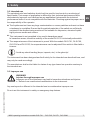
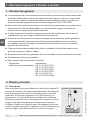
2. Design and function
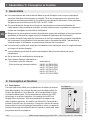
2.1 Description
This instrument is used for the detection of limit levels in liquids.
The measuring principle is independent of refractive index,
density, conductivity and dielectric constant. The switches consist
of an infrared LED and a phototransistor. The light of the LED is
directed into a prism. So long as the sensor tip of the prism is in
the gaseous phase, the light is reflected within the prism to the
receiver. When the liquid in the vessel rises and wets the glass
tip, the infrared lightbeam into the liquid is interrupted and only a
small portion reaches the receiver.
Operating principle
Gas
Liquid
1. General information / 2. Design and function

14235426.01 08/2017 EN/DE/FR/ES
WIKA operating instructions models OLS-C01 ... OLS-C05, OLS-F1, OLS-5200 5
EN
In addition, level control can be carried out with greater precision and filling levels can be
monitored in very small vessels. The sensor thus offers a very wide field of application for
limit value detection.
The optoelectronic level switches are suitable for liquids such as oils, water, distilled water,
aqueous media and for foam detection (with trimmer option).
The integrated switch electronics offer an automatic adjustment so that there is a wide field
of application. For the output, there is an pnp transistor switching output.
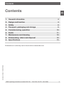
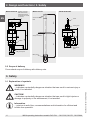
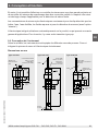
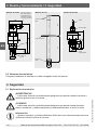
2.2 Instrument construction
Depending on the switch type, the instruments are fitted with different process connections.
These contain a glass prism and the electronics responsible for the evaluation.
Dimensions in mm
2. Design and function
Glass prism
Circular connector
M8 x 1, 3-pin
(alternatively
cable connection)
Cable outlet
M16 x 1.5, PG11
(alternatively
circular or angular
connector)
Cable
Cable
Glass
prism
Model OLS-C01 Model OLS-C02 Model OLS-C04
Function
indicator LED
Cable outlet
(alternatively circular
connector)
Glass
prism
Function
indicator LED

14235426.01 08/2017 EN/DE/FR/ES
6 WIKA operating instructions models OLS-C01 ... OLS-C05, OLS-F1, OLS-5200
EN
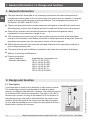
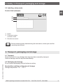
100 *
EL
7
13
2. Design and function / 3. Safety
Glass prism
Glass prism
SW30
Angular connector
EN 175301-803 A
(alternatively cable
connection or circular
connector)
Model OLS-C05 Model OLS-F1 Model OLS-5200
Clamp connection
Circular connector
M12
2.3 Scope of delivery
Cross-check scope of delivery with delivery note.
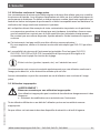
3. Safety
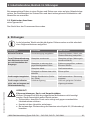
3.1 Explanation of symbols
WARNING!
... indicates a potentially dangerous situation that can result in serious injury or
death, if not avoided.
CAUTION!
... indicates a potentially dangerous situation that can result in light injuries or
damage to property or the environment, if not avoided.
Information
... points out useful tips, recommendations and information for efficient and
trouble-free operation.
Cable gland
Cable
Borosilicate
glass

14235426.01 08/2017 EN/DE/FR/ES
WIKA operating instructions models OLS-C01 ... OLS-C05, OLS-F1, OLS-5200 7
EN
3. Safety
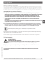
3.2 Intended use
The optoelectronic level switches should only be used for level control or monitoring of
liquid media. Their scope of application is defined by their technical performance limits
and materials. Improper use is defined as any application that exceeds the technical
performance limits or is not compatible with the materials. Checking against improper use is
the responsibility of the operator.
■
The liquids must not have any large contamination or coarse particles and must not have
a tendency to crystallise. Ensure that the wetted materials of the switch are sufficiently
resistant to the medium being monitored. Not suitable for dispersion, abrasive liquids,
highly viscous media and colours.
■
This instrument is not permitted to be used in hazardous areas!
In hazardous areas, check the usability of the model OLS-C51 intrinsically safe switch.
■
The responsiveness of the instrument is preset. With the models OLS-C01, OLS-C02,
OLS-C04 and OLS-C05, the responsiveness can be adjusted if the switch is fitted with a
trimmer.
Avoid any shock loading (drops, impacts, etc.) to the glass tip!
The instrument has been designed and built solely for the intended use described here, and
may only be used accordingly.
The manufacturer shall not be liable for claims of any type based on operation contrary to
the intended use.
3.3 Improper use
WARNING!
Injuries through improper use
Improper use of the instrument can lead to hazardous situations and injuries.
▶
Refrain from unauthorised modifications to the instrument.
Any use beyond or different to the intended use is considered as improper use.
Do not use this instrument in safety or emergency stop devices.

14235426.01 08/2017 EN/DE/FR/ES
8 WIKA operating instructions models OLS-C01 ... OLS-C05, OLS-F1, OLS-5200
EN
3.4 Responsibility of the operator
The instrument is used in the industrial sector. The operator is therefore responsible for
legal obligations regarding safety at work.
The safety instructions within these operating instructions, as well as the safety, accident
prevention and environmental protection regulations for the application area must be
maintained.
To ensure safe working on the instrument, the operating company must ensure
■
that the operating personnel are regularly instructed in all topics regarding work safety,
first aid and environmental protection and know the operating instructions and in
particular, the safety instructions contained therein.
■
that the instrument is suitable for the particular application in accordance with its
intended use.
3.5 Personnel qualification
WARNING!
Risk of injury should qualification be insufficient
Improper handling can result in considerable injury and damage to equipment.
▶
The activities described in these operating instructions may only be carried
out by skilled personnel who have the qualifications described below.
Skilled personnel
Skilled personnel, authorised by the operator, are understood to be personnel who, based
on their technical training, knowledge of measurement and control technology and on
their experience and knowledge of country-specific regulations, current standards and
directives, are capable of carrying out the work described and independently recognising
potential hazards.
3. Safety

14235426.01 08/2017 EN/DE/FR/ES
WIKA operating instructions models OLS-C01 ... OLS-C05, OLS-F1, OLS-5200 9
EN
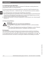
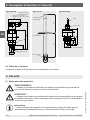
3.6 Labelling, safety marks
Product label (example)
3. Safety / 4. Transport, packaging and storage
Model
P# product number
S# serial number
Electrical connection
Before mounting and commissioning the instrument, ensure you read the
operating instructions!
4. Transport, packaging and storage
4.1 Transport
Check the switch for any damage that may have been caused by transport.
Obvious damage must be reported immediately.
4.2 Packaging and storage
Do not remove packaging until just before mounting.
Permissible conditions at the place of storage:
Storage temperature: -30 ... +70 °C

14235426.01 08/2017 EN/DE/FR/ES
10 WIKA operating instructions models OLS-C01 ... OLS-C05, OLS-F1, OLS-5200
EN
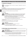
5. Commissioning, operation
When unpacking the switch, check all components for any external damage. Prior to
installation, a functional check can also be carried out. For this, the instrument should be
connected temporarily and the glass prism dipped in and out of a glass of liquid to test it.
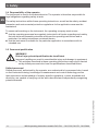
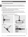
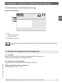
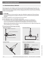
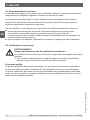
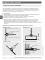
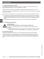
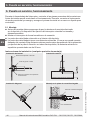
5.1 Mounting
■
Before installation, it must be ensured that the mounting hole and the fixing device for
the switches in the vessel are correct in size and dimension.
■
Mount the switch, pressure-sealed, into the process connection.
■
The glass tip must protrude into the vessel.
■
Following installation, the glass tip should have a distance of at least 10 mm to the
opposite wall. This minimum clearance can vary dependent upon the geometry and
surface finish of the wall. Note: With electropolished pipes, the minimum distance to the
opposite surface must be a minimum of 20 mm.
Mounting instructions (mounting position as required)
Horizontal installation Vertical installation
Angled installation
Installation in elongated fitting
Vessel or pipe wall
Rubber or metal sealing
Fitting with sealing face
Elongated fitting
Insulation
5. Commissioning, operation

14235426.01 08/2017 EN/DE/FR/ES
WIKA operating instructions models OLS-C01 ... OLS-C05, OLS-F1, OLS-5200 11
EN
For horizontal installation in a fitting and installation from the bottom, make sure there is
a drainage inclination in order to avoid residual liquid in the fitting/pipe and, with that, the
resulting faulty detection of the media.
5.2 Electrical connection
see product label
The instrument must be grounded via the process connection.
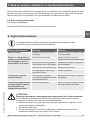
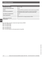
6. Faults
The following table contains the most frequent causes of faults and the
necessary countermeasures.
Faults Causes Measures
No function Failure in power supply Measure voltage, check cable or
plug connection
Despite a change in
level, no alteration in the
display and no switching
of the output
Glass tip dirty Clean the glass tip (introduce
service intervals)
Glass tip too close to an opposite
surface
Increase the distance, change
the mounting location
Glass tip defective Replace instrument
Liquid in the fitting cannot run out Check installation
Instrument responds
inversely
Wrong switching function
(normally open, normally closed)
Replace instrument / match to
control
Instrument obviously
does not respond or
responds too slowly on a
change of level
Switching delay Use an instrument with suitable
switching delay
CAUTION!
Physical injuries and damage to property and the environment
If faults cannot be eliminated by means of the listed measures, the instrument
must be taken out of operation immediately.
▶
Ensure that there is no longer any pressure present and protect against being
put into operation accidentally.
▶
Contact the manufacturer.
▶
If a return is needed, please follow the instructions given in chapter 8.2
“Return”.
5. Commissioning, operation / 6. Faults

14235426.01 08/2017 EN/DE/FR/ES
12 WIKA operating instructions models OLS-C01 ... OLS-C05, OLS-F1, OLS-5200
EN
7. Maintenance and cleaning
For contact details, please see chapter 1 “General information” or the back page
of the operating instructions.
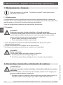
7.1 Maintenance
When used properly, the optoelectronic level switches work maintenance-free. They must
be subjected to visual inspection within the context of regular servicing, however, and
included in the vessel pressure test.
Repairs must only be carried out by the manufacturer.
7.2 Cleaning
CAUTION!
Physical injuries and damage to property and the environment
Improper cleaning may lead to physical injuries and damage to property and the
environment. Residual media in the dismounted instrument can result in a risk to
persons, the environment and equipment.
▶
Rinse or clean the removed instrument.
▶
Sufficient precautionary measures must be taken.
1. Prior to cleaning, properly disconnect the instrument from the process and the power
supply.
2. Clean the instrument carefully with a moist cloth.
3. Electrical connections must not come into contact with moisture!
CAUTION!
Damage to property
Improper cleaning may lead to damage to the instrument!
▶
Do not use any aggressive cleaning agents.
▶
Do not use any hard, pointed or abrasive objects for cleaning.
8. Dismounting, return and disposal
WARNING!
Physical injuries and damage to property and the environment through
residual media
Residual media in the dismounted instrument can result in a risk to persons, the
environment and equipment.
▶
Wash or clean the dismounted instrument, in order to protect persons and the
environment from exposure to residual media.
7. Maintenance, cleaning / 8. Dismounting, return, disposal

14235426.01 08/2017 EN/DE/FR/ES
WIKA operating instructions models OLS-C01 ... OLS-C05, OLS-F1, OLS-5200 13
EN
8.1 Dismounting
Only disconnect the measuring instrument once the system has been depressurised and
the power disconnected! If necessary, the measuring line must have strain relief.
8.2 Return
Wash or clean the dismounted switch before returning it, in order to protect personnel and
the environment from exposure to residual media.
Information on returns can be found under the heading “Service” on our local
website.
8.3 Disposal
Incorrect disposal can put the environment at risk.
Dispose of instrument components and packaging materials in an environmentally
compatible way and in accordance with the country-specific waste disposal regulations.
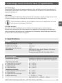
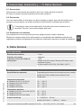
9. Specifications
General data
Measurement accuracy ±2 mm
Mounting position as required
Visual indication of the switching
status
1 LED
Model OLS-C05: With trimmer option, internal LED to
ease adjustment
Not with models OLS-C02, OLS-5200, OLS-F1
Design data
Responsiveness Preset for the detection of aqueous media and oils
Model OLS-C04: Also for the detection of refrigerants
Medium temperature
■
Models OLS-C01, OLS-C02
■
Models OLS-C04, OLS-F1
■
Model OLS-C05
■
Model OLS-5200
-30 ... +100 °C
-40 ... +100 °C
-40 ... +170 °C
-40 ... +130 °C
Ambient temperature
■
Models OLS-C01, OLS-C02, OLS-F1
■
Model OLS-C04
■
Models OLS-C05, OLS-5200
-25 ... +70 °C
-30 ... +70 °C
-30 ... +80 °C
Operating pressure 0 … 2.5 MPa (0 … 25 bar)
Model OLS-C04: 0 … 4 MPa (0 … 40 bar)
8. Dismounting, return and disposal / 9. Specifications

14235426.01 08/2017 EN/DE/FR/ES
14 WIKA operating instructions models OLS-C01 ... OLS-C05, OLS-F1, OLS-5200
EN
Electrical data
Power supply DC 12 ... 32 V
Max. current supply 40 mA
Output PNP transistor, protected against reverse polarity
Switching function Normally open (closed in medium) or normally closed (open
in medium)
Switching current 200 mA
Ingress protection IP65
Model OLS-F1 with protection cap: IP69K
Number of switch points 1
For further specifications see WIKA data sheets
LM 31.31 (OLS-C01),
LM 31.32 (OLS-C02),
LM 31.33 (OLS-C05),
LM 31.34 (OLS-C04),
LM 31.05 (OLS-F1) or
LM 31.06 (OLS-5200) and order documentation.
9. Specifications

14235426.01 08/2017 EN/DE/FR/ES
WIKA Betriebsanleitung Typen OLS-C01 ... OLS-C05, OLS-F1, OLS-5200 15
DE
Inhalt
Inhalt
Konformitätserklärungen finden Sie online unter www.wika.de.
1. Allgemeines 16
2. Aufbau und Funktion 16
3. Sicherheit 18
4. Transport, Verpackung und Lagerung 21
5. Inbetriebnahme, Betrieb 22
6. Störungen 23
7. Wartung und Reinigung 24
8. Demontage, Rücksendung und Entsorgung 24
9. Technische Daten 25

14235426.01 08/2017 EN/DE/FR/ES
16 WIKA Betriebsanleitung Typen OLS-C01 ... OLS-C05, OLS-F1, OLS-5200
DE
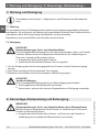
1. Allgemeines
■
Die in der Betriebsanleitung beschriebenen Füllstandsschalter werden nach dem aktuel-
len Stand der Technik konstruiert und gefertigt. Alle Komponenten unterliegen während
der Fertigung strengen Qualitäts- und Umweltkriterien. Unsere Managementsysteme
sind nach ISO 9001 und ISO 14001 zertifiziert.
■
Diese Betriebsanleitung gibt wichtige Hinweise zum Umgang mit dem Gerät. Vorausset-
zung für sicheres Arbeiten ist die Einhaltung aller angegebenen Sicherheitshinweise und
Handlungsanweisungen.
■
Die für den Einsatzbereich des Gerätes geltenden örtlichen Unfallverhütungsvorschriften
und allgemeinen Sicherheitsbestimmungen einhalten.
■
Die Betriebsanleitung ist Produktbestandteil und muss in unmittelbarer Nähe des
Gerätes für das Fachpersonal jederzeit zugänglich aufbewahrt werden. Betriebsanlei-
tung an nachfolgende Benutzer oder Besitzer des Gerätes weitergeben.
■
Das Fachpersonal muss die Betriebsanleitung vor Beginn aller Arbeiten sorgfältig durch-
gelesen und verstanden haben.
■
Es gelten die allgemeinen Geschäftsbedingungen in den Verkaufsunterlagen.
■
Technische Änderungen vorbehalten.
■
Weitere Informationen:
- Internet-Adresse: www.wika.de / www.wika.com
- Zugehöriges Datenblatt: LM 31.31 (OLS-C01),
LM 31.32 (OLS-C02),
LM 31.33 (OLS-C05),
LM 31.34 (OLS-C04),
LM 31.05 (OLS-F1),
LM 31.06 (OLS-5200)
2. Aufbau und Funktion
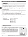
2.1 Beschreibung
Dieses Gerät dient zur Grenzstandserfassung von Flüssigkeiten.
Das Messprinzip ist unabhängig von Brechzahl, Dichte, Leitfä-
higkeit und Dielektrizitätskonstante. Die Schalter beinhalten
eine Infrarot-LED und einen Fototransistor. Das Licht der LED
wird in ein Prisma eingestrahlt. Solange sich die Sensorspitze
des Prismas in der Gasphase befindet, wird das Licht innerhalb
des Prismas zum Empfänger reflektiert. Steigt die Flüssigkeit
im Behälter und benetzt die Glasspitze, wird das Infrarotlicht in
der Flüssigkeit gebrochen und nur ein kleiner Teil erreicht den
Empfänger.
Funktionsprinzip
Gas
Flüssigkeit
1. Allgemeines / 2. Aufbau und Funktion

14235426.01 08/2017 EN/DE/FR/ES
WIKA Betriebsanleitung Typen OLS-C01 ... OLS-C05, OLS-F1, OLS-5200 17
DE
Außerdem können Niveauregelungen mit großer Präzision durchgeführt sowie Füllstände
in sehr kleinen Behältern überwacht werden. Der Sensor bietet somit einen sehr breiten
Anwendungsbereich zur Grenzwerterfassung.
Die optoelektronischen Füllstandsschalter sind geeignet für Flüssigkeiten wie Öle, Wasser,
destilliertes Wasser, wässrige Medien und für Schaumdetektion (mit Option Trimmer).
Die integrierte Schaltelektronik sorgt für einen automatischen Abgleich, so dass sich ein
breiter Anwendungsbereich ergibt. Als Ausgang steht ein pnp-Transistor-Schaltausgang zur
Verfügung.
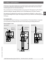
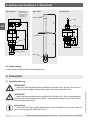
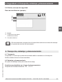
2.2 Geräteaufbau
Die Geräte sind je nach Schaltertyp mit unterschiedlichen Prozessanschlüssen ausgestat-
tet. Sie enthalten ein Glasprisma und eine für die Auswertung zuständige Elektronik.
Abmessungen in mm
2. Aufbau und Funktion
Glasprisma
Rundstecker
M8 x 1, 3-polig
(alternativ
Kabelanschluss)
Kabelausgang
M16 x 1,5, PG11
(alternativ
Rund- oder
Winkelstecker)
Kabel
Kabel
Glas-
prisma
Typ OLS-C01 Typ OLS-C02 Typ OLS-C04
Funktions-
anzeige LED
Kabelausgang
(alternativ Rundstecker)
Glasprisma
Funktions-
anzeige LED

14235426.01 08/2017 EN/DE/FR/ES
18 WIKA Betriebsanleitung Typen OLS-C01 ... OLS-C05, OLS-F1, OLS-5200
DE
100 *
EL
7
13
2. Aufbau und Funktion / 3. Sicherheit
Glasprisma
Glasprisma
SW30
Winkelstecker
EN 175301-803 A
(alternativ Kabel-
anschluss oder
Rundstecker)
Typ OLS-C05 Typ OLS-F1 Typ OLS-5200
Clampanschluss
Rundstecker M12
2.3 Lieferumfang
Lieferumfang mit dem Lieferschein abgleichen.
3. Sicherheit
3.1 Symbolerklärung
WARNUNG!
... weist auf eine möglicherweise gefährliche Situation hin, die zum Tod oder zu
schweren Verletzungen führen kann, wenn sie nicht gemieden wird.
VORSICHT!
... weist auf eine möglicherweise gefährliche Situation hin, die zu geringfügigen
oder leichten Verletzungen bzw. Sach- und Umweltschäden führen kann, wenn
sie nicht gemieden wird.
Information
... hebt nützliche Tipps und Empfehlungen sowie Informationen für einen effizien-
ten und störungsfreien Betrieb hervor.
Kabel-
verschraubung
Kabel
Borsilikatglas

14235426.01 08/2017 EN/DE/FR/ES
WIKA Betriebsanleitung Typen OLS-C01 ... OLS-C05, OLS-F1, OLS-5200 19
DE
3. Sicherheit
3.2 Bestimmungsgemäße Verwendung
Die optoelektronischen Füllstandsschalter sind ausschließlich zur Füllstandssteuerung bzw.
-überwachung von flüssigen Medien zu verwenden. Ihr Einsatzbereich ergibt sich aus den
technischen Leistungsgrenzen und Werkstoffen. Als Fehlgebrauch gilt jede Verwendung,
die die technischen Leistungsgrenzen überschreitet oder mit den Werkstoffen unverträglich
ist. Eine Prüfung auf Fehlgebrauch obliegt dem Betreiber.
■
Die Flüssigkeiten dürfen keine starken Verschmutzungen oder Grobteile aufweisen und
nicht zum Auskristallisieren neigen. Es ist sicherzustellen, dass die medienberührenden
Werkstoffe des Schalters gegen das zu überwachende Medium ausreichend beständig
sind. Nicht geeignet für Dispersion, abrasive Flüssigkeiten, hochviskose Medien und
Farben.
■
Dieses Gerät ist nicht für den Einsatz in explosionsgefährdeten Bereichen zugelassen!
In explosionsgefährdeten Bereichen die Einsetzbarkeit des eigensicheren Schalters
Typ OLS-C51 prüfen.
■
Die Ansprechempfindlichkeit der Geräte ist voreingestellt. Bei den Typen OLS-C01,
OLS-C02, OLS-C04 und OLS-C05 kann die Ansprechempfindlichkeit verstellt werden,
wenn die Schalter mit einem Trimmer ausgestattet sind.
Eine Stoßbelastung (Herunterfallen, Anschlagen, u. Ä.) der Glasspitze
vermeiden!
Das Gerät ist ausschließlich für den hier beschriebenen bestimmungsgemäßen Verwen-
dungszweck konzipiert und konstruiert und darf nur dementsprechend verwendet werden.
Ansprüche jeglicher Art aufgrund von nicht bestimmungsgemäßer Verwendung sind ausge-
schlossen.
3.3 Fehlgebrauch
WARNUNG!
Verletzungen durch Fehlgebrauch
Fehlgebrauch des Gerätes kann zu gefährlichen Situationen und Verletzungen
führen.
▶
Eigenmächtige Umbauten am Gerät unterlassen.
Jede über die bestimmungsgemäße Verwendung hinausgehende oder andersartige Benut-
zung gilt als Fehlgebrauch.
Dieses Gerät nicht in Sicherheits- oder in Not-Aus-Einrichtungen benutzen.

14235426.01 08/2017 EN/DE/FR/ES
20 WIKA Betriebsanleitung Typen OLS-C01 ... OLS-C05, OLS-F1, OLS-5200
DE
3.4 Verantwortung des Betreibers
Das Gerät wird im gewerblichen Bereich eingesetzt. Der Betreiber unterliegt daher den
gesetzlichen Pflichten zur Arbeitssicherheit.
Die Sicherheitshinweise dieser Betriebsanleitung, sowie die für den Einsatzbereich des
Gerätes gültigen Sicherheits-, Unfallverhütungs- und Umweltschutzvorschriften einhalten.
Für ein sicheres Arbeiten am Gerät muss der Betreiber sicherstellen,
■
dass das Bedienpersonal regelmäßig in allen zutreffenden Fragen von Arbeitssicherheit,
Erste Hilfe und Umweltschutz unterwiesen wird, sowie die Betriebsanleitung und insbe-
sondere die darin enthaltenen Sicherheitshinweise kennt.
■
dass das Gerät gemäß der bestimmungsgemäßen Verwendung für den Anwendungsfall
geeignet ist.
3.5 Personalqualifikation
WARNUNG!
Verletzungsgefahr bei unzureichender Qualifikation
Unsachgemäßer Umgang kann zu erheblichen Personen- und Sachschäden
führen.
▶
Die in dieser Betriebsanleitung beschriebenen Tätigkeiten nur durch Fachper-
sonal nachfolgend beschriebener Qualifikation durchführen lassen.
Fachpersonal
Das vom Betreiber autorisierte Fachpersonal ist aufgrund seiner fachlichen Ausbildung,
seiner Kenntnisse der Mess- und Regelungstechnik und seiner Erfahrungen sowie Kennt-
nis der landesspezifischen Vorschriften, geltenden Normen und Richtlinien in der Lage, die
beschriebenen Arbeiten auszuführen und mögliche Gefahren selbstständig zu erkennen.
3. Sicherheit
La page est en cours de chargement...
La page est en cours de chargement...
La page est en cours de chargement...
La page est en cours de chargement...
La page est en cours de chargement...
La page est en cours de chargement...
La page est en cours de chargement...
La page est en cours de chargement...
La page est en cours de chargement...
La page est en cours de chargement...
La page est en cours de chargement...
La page est en cours de chargement...
La page est en cours de chargement...
La page est en cours de chargement...
La page est en cours de chargement...
La page est en cours de chargement...
La page est en cours de chargement...
La page est en cours de chargement...
La page est en cours de chargement...
La page est en cours de chargement...
La page est en cours de chargement...
La page est en cours de chargement...
La page est en cours de chargement...
La page est en cours de chargement...
La page est en cours de chargement...
La page est en cours de chargement...
La page est en cours de chargement...
La page est en cours de chargement...
La page est en cours de chargement...
La page est en cours de chargement...
La page est en cours de chargement...
La page est en cours de chargement...
-
 1
1
-
 2
2
-
 3
3
-
 4
4
-
 5
5
-
 6
6
-
 7
7
-
 8
8
-
 9
9
-
 10
10
-
 11
11
-
 12
12
-
 13
13
-
 14
14
-
 15
15
-
 16
16
-
 17
17
-
 18
18
-
 19
19
-
 20
20
-
 21
21
-
 22
22
-
 23
23
-
 24
24
-
 25
25
-
 26
26
-
 27
27
-
 28
28
-
 29
29
-
 30
30
-
 31
31
-
 32
32
-
 33
33
-
 34
34
-
 35
35
-
 36
36
-
 37
37
-
 38
38
-
 39
39
-
 40
40
-
 41
41
-
 42
42
-
 43
43
-
 44
44
-
 45
45
-
 46
46
-
 47
47
-
 48
48
-
 49
49
-
 50
50
-
 51
51
-
 52
52


