Maytag MED9600SQ0 Manuel utilisateur
- Catégorie
- Laveuses sécheuses
- Taper
- Manuel utilisateur

MAY['AG ®
• TM
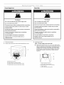
FRONT-LOADING ELECTRIC DRYER
For questions about features, operation/performance, parts, accessories or service, call: 1-800-688-9900
In Canada, call : 1-800-807-6777 or visit our website at...
www.maytag.com or www.maytag.ca
SECADORA ELI_CTRICA DE CARGA FRONTAL
Si tiene preguntas respecto alas caracteristicas, funcionamiento/rendimiento, partes, accesorios o servicio t6cnico,
Ilame al: 1-800-688-9900
o visite nuestro sitio web en...www.maytag.com
SF,CHEUSE F,LECTRIQUE A CHARGEMENT
FRONTAL
Au Canada, composez le 1-800-807-6777
ou visitez notre site web &...www.maytag.ca
Table of Contents/indice/Table des matieres .................................................................. 2
W10099070A

TABLE OF CONTENTS
DRYER SAFETY .............................................................................. 3
INSTALLATION INSTRUCTIONS .................................................. 4
Tools and Parts ............................................................................ 4
Options ......................................................................................... 4
Location Requirements ................................................................ 5
Electrical Requirements - U.S.A. Only ......................................... 7
Electrical Requirements - Canada Only ....................................... 8
Electrical Connection - U.S.A. Only ............................................. 9
Venting Requirements ................................................................ 14
Plan Vent System ....................................................................... 15
Install Vent System ..................................................................... 16
Install Leveling Legs ................................................................... 16
Level Dryer ................................................................................. 17
Connect Vent .............................................................................. 17
Reverse Door Swing .................................................................. 17
Complete Installation ................................................................. 18
DRYER USE .................................................................................. 19
Starting Your Dryer ..................................................................... 19
Stopping Your Dryer .................................................................. 20
Pausing or Restarting ................................................................. 20
Control Locked ........................................................................... 20
Drying and Cycle Tips ................................................................ 20
Status Lights .............................................................................. 21
Cycles ......................................................................................... 21
Additional Features .................................................................... 22
Drying Rack ................................................................................ 23
DRYER CARE .............................................................................. 24
Cleaning the Dryer Location ...................................................... 24
Cleaning the Lint Screen ............................................................ 24
Cleaning the Dryer Interior ......................................................... 24
Removing Accumulated Lint ...................................................... 24
Vacation and Moving Care ......................................................... 24
Changing the Drum Light ........................................................... 25
TROUBLESHOOTING .................................................................. 25
ASSISTANCE OR SERVICE ......................................................... 27
WARRANTY .................................................................................. 28
INDICE
SEGURIDAD DE LA SECADORA ................................................ 29
INSTRUCCIONES DE INSTALACION ......................................... 30
Herramientas y piezas ................................................................ 30
Opciones .................................................................................... 30
Requisitos de ubicaci6n ............................................................ 30
Requisitos electricos - $61o en EE. UU..................................... 32
Conexi6n electrica - S61oen EE. UU......................................... 34
Requisitos de ventilaci6n ........................................................... 39
Planificaci6n del sistema de ventilaci6n .................................... 40
Instalacidn del sistema de ventilaci6n ....................................... 41
Instalaci6n de las patas niveladoras .......................................... 41
Nivelaci6n de la secadora .......................................................... 42
Conexi6n del ducto de escape .................................................. 42
C6mo invertir el cierre de la puerta ............................................ 42
Complete la instalacidn - EE. UU............................................... 44
USO DE LA SECADORA .............................................................. 45
Puesta en marcha de la secadora ............................................. 45
Detencidn de la marcha de la secadora .................................... 46
Pausa o reanudaci6n de la marcha ........................................... 46
Control bloqueado ..................................................................... 46
Sugerencias de ciclos y secado ................................................ 46
Luces de estado ......................................................................... 47
Ciclos .......................................................................................... 47
Caracterfsticas adicionales ........................................................ 48
Estante de secado ...................................................................... 49
CUIDADO DE LA SECADORA ..................................................... 50
Limpieza del lugar donde esta la secadora ............................... 50
Limpieza del filtro de pelusa ...................................................... 50
Limpieza del interior de la secadora .......................................... 51
Eliminaci6n de pelusa acumulada ............................................. 51
Cuidado para las vacaciones y la mudanza .............................. 51
Cambio de la luz del tambor ...................................................... 51
SOLUCION DE PROBLEMAS ...................................................... 52
AYUDA O SERVICIO TECNICO ................................................... 54
GARANT|A ..................................................................................... 55
TABLE DES MATIERES
SECURIT¢: DE LA SECHEUSE .................................................... 56
INSTRUCTIONS D'INSTALLATION ............................................. 57
Outillage et pieces ...................................................................... 57
Options ....................................................................................... 57
Exigences d'emplacement ......................................................... 57
Specifications electriques .......................................................... 59
Exigences concernant I'evacuation ........................................... 60
Planification du systeme d'evacuation ...................................... 61
Installation du syst_me d'6vacuation ......................................... 63
Installation des pieds de nivellement ......................................... 63
Mise a niveau de la secheuse .................................................... 63
Raccordement du conduit d'evacuation ................................... 63
Inversion du sens d'ouverture de la porte ................................. 63
Achever I'installation .................................................................. 65
UTILISATION DE LA SI:!:CHEUSE................................................ 66
Mise en marche de la secheuse ................................................ 66
Arr6t de la secheuse ................................................................... 67
Pause ou remise en marche ....................................................... 67
Verrouillage des commandes ..................................................... 67
Conseils pour le sechage et les programmes ........................... 67
Temoins lumineux ...................................................................... 68
Programmes ............................................................................... 68
Caracteristiques supplementaires ............................................. 69
Grille de sechage ........................................................................ 70
ENTRETIEN DE LA S¢CI-IEUSE ................................................. 71
Nettoyage de I'emplacement de la secheuse ........................... 71
Nettoyage du filtre a charpie ...................................................... 71
Nettoyage de I'interieur de la secheuse ..................................... 71
Retrait de la charpie accumulee ................................................ 72
Precautions a prendre pour les vacances et avant un
demenagement .......................................................................... 72
Changement de I'ampoule d'eclairage du tambour .................. 72
DI:!:PANNAGE................................................................................. 72
ASSISTANCE OU SERVICE ......................................................... 74
GARANTI E ..................................................................................... 75

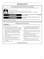
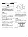
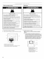
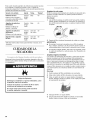
DRYER SAFETY
Your safety and the safety of others are very important.
We have provided many important safety messages in this manual and on your appliance. Always read and obey all safety
messages.
This is the safety alert symbol.
This symbol alerts you to potential hazards that can kill or hurt you and others.
All safety messages will follow the safety alert symbol and either the word "DANGER" or "WARNING."
These words mean:
You can be killed or seriously injured if you don't immediately
follow instructions.
You can be killed or seriously injured if you don't follow
instructions.
All safety messages will tell you what the potential hazard is, tell you how to reduce the chance of injury, and tell you what can
happen if the instructions are not followed.
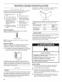
iMPORTANT SAFETY iNSTRUCTiONS
WARNING: To reduce the risk of fire, electric shock, or injury to persons when using the dryer, follow basic precautions,
including the following:
[] Read all instructions before using the dryer.
[] Do not place items exposed to cooking oils in your dryer.
Items contaminated with cooking oils may contribute to
a chemical reaction that could cause a load to catch fire.
[] Do not dry articles that have been previously cleaned in,
washed in, soaked in, or spotted with gasoline, dry-
cleaning solvents, or other flammable or explosive
substances as they give off vapors that could ignite or
explode.
[] Do not allow children to play on or in the dryer. Close
supervision of children is necessary when the dryer is
used near children.
[] Before the dryer is removed from service or discarded,
remove the door to the drying compartment.
[] Do not reach into the dryer if the drum is moving.
[] Do not install or store the dryer where it will be exposed
to the weather.
[] Do not tamper with controls.
[] Do not repair or replace any part of the dryer or attempt
any servicing unless specifically recommended in this
Use and Care Guide or in published user-repair
instructions that you understand and have the skills to
carry out.
[] Do not use fabric softeners or products to eliminate static
unless recommended by the manufacturer of the fabric
softener or product.
[] Do not use heat to dry articles containing foam rubber or
similarly textured rubber-like materials.
[] Clean lint screen before or after each load.
[] Keep area around the exhaust opening and adjacent
surrounding areas free from the accumulation of lint, dust,
and dirt.
[] The interior of the dryer and exhaust vent should be
cleaned periodically by qualified service personnel.
[] See installation instructions for grounding requirements.
SAVE TH ESE iNSTRUCTiONS

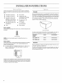
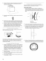
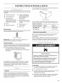
INSTALLATION INSTRUCTIONS
Gather the required tools and parts before starting installation.
Read and follow the instructions provided with any tools listed
here.
• Flat-blade screwdriver • Vent clamps
• #2 Phillips screwdriver • Caulking gun and
compound (for installing
• Adjustable wrench that
opens to 1" (2.5 cm) or new exhaust vent)
hex-head socket wrench • Tin snips (new vent
(for adjusting dryer feet) installations)
• Wire stripper (direct wire • 1/4"nut driver
installations) (recommended)
• Level • Tape measure
Parts supplied
Remove parts packages from dryer drum. Check that all parts are
included.
4 Leveling legs
NOTE: Do not use leveling legs if installing the dryer on a
pedestal.
Parts needed
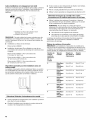
Check local codes. Check existing electrical supply and venting.
See "Electrical Requirements" and "Venting Requirements"
before purchasing parts.
• For close-clearance installations between 31.5" (80.01 cm)
and 37" (93.98 cm), see "Plan Vent System" section for
venting requirements.
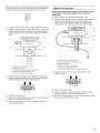
I_- 37" --_1
(93.98 cm)
Mobile home installations require metal exhaust system hardware
available for purchase from the dealer from whom you purchased
your dryer. For further information, please refer to the "Assistance
or Service" section of this manual.
Pedestal
Are you placing the dryer on a pedestal? You have the option of
purchasing a pedestal separately for this dryer. You may select a
15.5" (39.4 cm) pedestal. This pedestal will add to the total height
of the dryer for a total height of approximately 53.5" (135.9 cm).
For a garage installation, you will need to place the pedestal at
least 3.5" (8.9 cm) above the floor.
Optional pedestal
To order, call the dealer from whom you purchased your dryer or
refer to the "Assistance or Service" section of this manual.
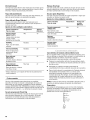
Pedestal Color Part Number
Height
15.5" (39.4 cm) White WHP1500SQ
15.5" (39.4 cm) Black WHP1500SB
Stack Kit
Are you planning to stack your washer and dryer? To do so, you
will need to purchase a Stack Kit.
To order, call the dealer from whom you purchased your dryer or
refer to the "Assistance or Service" section of this manual. Ask
for Part Number 8212640.

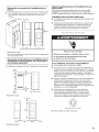
ExplosionHazard
Keep flammable materials and vapors, such as
gasoline, away from dryer.
Place dryer at least 18 inches (46 cm) above the floor
for a garage installation.
Failure to do so can result in death, explosion, or fire.
You will need
• A location that allows for proper exhaust installation. See
"Venting Requirements."
• A separate 30-amp circuit.
• If you are using a power supply cord, a grounded electrical
outlet located within 2 ft (61 cm) of either side of the dryer.
See "Electrical Requirements."
• A sturdy floor to support the total dryer weight of 200 Ibs
(90.7 kg). The combined weight of a companion appliance
should also be considered.
A level floor with a maximum slope of 1" (2.5 cm) under entire
dryer. If slope is greater than 1" (2.5 cm), install Extended
Dryer Feet Kit, Part Number 279810. Clothes may not tumble
properly and automatic sensor cycles may not operate
correctly if dryer is not level.
• For a garage installation, you will need to place the dryer at
least 18" (46 cm) above the floor. If using a pedestal, you will
need 18" (46 cm) to the bottom of the dryer.
Do not operate your dryer at temperatures below 45°F (7°C). At
lower temperatures, the dryer might not shut off at the end of an
automatic cycle. This can result in longer drying times.
The dryer must not be installed or stored in an area where it will
be exposed to water and/or weather.
Check code requirements. Some codes limit, or do not permit,
installation of the dryer in garages, closets, mobile homes or
sleeping quarters. Contact your local building inspector.
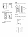
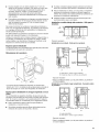
Installation clearances
The location must be large enough to allow the dryer door to
open fully.
Dryer Dimensions
*Most installations require a minimum 5" (12.7 cm) clearance
behind the dryer for the exhaust vent with elbow. See "Venting
Requirements."
Installation spacing for recessed area or closet installation
The following spacing dimensions are recommended for this
dryer. This dryer has been tested for spacing of 0" (0 cm)
clearance on the sides and rear. Recommended spacing should
be considered for the following reasons:
• Additional spacing should be considered for ease of
installation and servicing.
• Additional clearances might be required for wall, door and
floor moldings.
• Additional spacing should be considered on all sides of the
dryer to reduce noise transfer.
For closet installation, with a door, minimum ventilation
openings in the top and bottom of the door are required.
Louvered doors with equivalent ventilation openings are
acceptable.
• Companion appliance spacing should also be considered.
Custom undercounter installation - Dryer only
1"* _ _-_27"--}_ _--- 1"*
2.5 crn 68.6 cm 2.5 cm
*Required spacing

Closet installation - Dryer only
I1"*_ 31,J_"_'ls"**l
48 in.2.
(310 cm 2)
(2.5crn) (80cm) {12.7crn)
A
A. Side view - closet or confined area
B. Closet door with vents
*Required spacing
**For side or bottom venting, O" (Ocm) spacing is allowed.
Recessed or closet installation - Dryer on pedestal
1" '--'_ I _'_ 27"''''"J_l 1_"-- 1"
(2.5cm) {68.6cm)
IB -1-141,mox,
H
1"'1I<- 31,J_"--_1_"**1
(2.5 cm) (2.5 cm) {80 cm) {12.7 cm)
A B
A. Recessed area
B. Side view - closet or confined area
*Required spacing
**For side or bottom venting, O" (Ocm) spacing is allowed.
Recommended installation spacing for cabinet
installation
• For cabinet installation, with a door, minimum ventilation
openings in the top of the cabinet are required.
,,
_,_ (17.8cm)_17.8 cm)
OI
_;28cm)
tl IV
5"** 31W' 1"-- 1" 27" 1"
(12.7 cm) (80.0 cm) (2.8 cm) (2.5 cm)(68.6 cm) (2.5 crn)
*Required spacing
**For side or bottom venting, O" (Ocm) spacing is allowed.
Recommended installation spacing for recessed or
closet installation, with stacked washer and dryer
The dimensions shown are for the recommended spacing.
48 in.2 *
(310 crn 2)
T
o
-- __
24 in? *
(188cm2)
i
3"* (7.6 cm)
T
!
3"* (7.8 crn)
*Required spacing
5"*--_"
(12.7cm)
6"* (_5.2 cm)
t
76"
(193 crn)
(2.5cm)
....._::_
-,_-27"_- _- I"
68.6 crn 2.5 crn
*Required spacing

Mobile home - Additional installation requirements
This dryer is suitable for mobile home installations. The
installation must conform to the Manufactured Home
Construction and Safety Standard, Title 24 CFR, Part 3280
(formerly the Federal Standard for Mobile Home Construction
and Safety, Title 24, HUD Part 280) or Standard CAN/CSA-Z240
MH.
Mobile home installations require:
• Metal exhaust system hardware, which is available for
purchase from your dealer.
Special provisions must be made in mobile homes to
introduce outside air into the dryer. The opening (such as a
nearby window) should be at least twice as large as the dryer
exhaust opening.
(
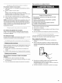
It is your responsibility
• Tocontact a qualified electrical installer.
To be sure that the electrical connection is adequate and in
conformance with the National Electrical Code, ANSl/NFPA
70-latest edition and all local codes and ordinances.
The National Electric Code requires a 4-wire power supply
connection for homes built after 1996, dryer circuits involved
in remodeling after 1996, and all mobile home installations.
A copy of the above code standards can be obtained from:
National Fire Protection Association, One Batterymarch Park,
Quincy, MA 02269.
To supply the required 3 or 4 wire, single phase, 120/240 volt,
60 Hz., AC only electrical supply (or 3 or 4 wire, 120/208 volt
electrical supply, if specified on the serial/rating plate) on a
separate 30-amp circuit, fused on both sides of the line. A
time-delay fuse or circuit breaker is recommended. Connect
to an individual branch circuit. Do not have a fuse in the
neutral or grounding circuit.
Do not use an extension cord.
If codes permit and a separate ground wire is used, it is
recommended that a qualified electrician determine that the
ground path is adequate.
Electrical Connection
To properly install your dryer, you must determine the type of
electrical connection you will be using and follow the instructions
provided for it here.
• This dryer is manufactured ready to install with a 3-wire
electrical supply connection. The neutral ground conductor is
permanently connected to the neutral conductor (white wire)
within the dryer. Ifthe dryer is installed with a 4-wire electrical
supply connection, the neutral ground conductor must be
removed from the external ground connector (green screw),
and secured under the neutral terminal (center or white wire)
of the terminal block. When the neutral ground conductor is
secured under the neutral terminal (center or white wire) of
the terminal block, the dryer cabinet is isolated from the
neutral conductor.
• If local codes do not permit the connection of a neutral
ground wire to the neutral wire, see "Optional 3-wire
connection" section.
A 4-wire power supply connection must be used when the
appliance is installed in a location where grounding through
the neutral conductor is prohibited. Grounding through the
neutral is prohibited for (1) new branch-circuit installations,
(2) mobile homes, (3) recreational vehicles, and (4) areas
where local codes prohibit grounding through the neutral
conductors.
If using a power supply cord:
Use a UL listed power supply cord kit marked for use with
clothes dryers. The kit should contain:
• A UL listed 30-amp power supply cord, rated 120/240 volt
minimum. The cord should be type SRD or SRDT and be at
least 4 ft (1.22 m) long. The wires that connect to the dryer
must end in ring terminals or spade terminals with upturned
ends.
• A UL listed strain relief.
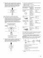
If your outlet looks like this:
4-wire receptacle (!4-30R)
Then choose a 4-wire power supply cord with ring or spade
terminals and UL listed strain relief. The 4-wire power supply
cord, at least 4 ft (1.22 m) long, must have four 10-gauge copper
wires and match a 4-wire receptacle of NEMA Type 14-30R. The
ground wire (ground conductor) may be either green or bare. The
neutral conductor must be identified by a white cover.
If your outlet looks like this:
3-wire receptacle (10-30R)
Then choose a 3-wire power supply cord with ring or spade
terminals and UL listed strain relief. The 3-wire power supply
cord, at least 4 ft (1.22 m) long, must have three 10-gauge copper
wires and match a 3-wire receptacle of NEMA Type 10-30R.
If connecting by direct wire:
Power supply cable must match power supply (4-wire or 3-wire)
and be:
• Flexible armored cable or nonmetallic sheathed copper cable
(with ground wire), protected with flexible metallic conduit. All
current-carrying wires must be insulated.
• 10-gauge solid copper wire (do not use aluminum).

[] Atleast5ft(1.52m)long.
GROUNDING INSTRUCTIONS
[] For a grounded, cord-connected dryer:
This dryer must be grounded. In the event of malfunction or
breakdown, grounding will reduce the risk of electric shock
by providing a path of least resistance for electric current.
This dryer uses a cord having an equipment-grounding
conductor and a grounding plug. The plug must be plugged
into an appropriate outlet that is properly installed and
grounded in accordance with all local codes and ordinances.
[] For a permanently connected dryer:
This dryer must be connected to a grounded metal,
permanent wiring system, or an equipment-grounding
conductor must be run with the circuit conductors and
connected to the equipment-grounding terminal or lead on
the dryer.
WARNING: Improper connection of the equipment-
grounding conductor can result in a risk of electric shock.
Check with a qualified electrician or service representative
or personnel if you are in doubt as to whether the dryer is
properly grounded. Do not modify the plug on the power
supply cord: if it will not fit the outlet, have a proper outlet
installed by a qualified electrician.
SAVE THESE INSTRUCTIONS
Electrical Shock Hazard
Plug into a grounded 4 prong outlet.
Failure to do so can result in death or electrical shock.
It is your responsibility
[] To contact a qualified electrical installer.
[] To be sure that the electrical connection is adequate and in
conformance with the Canadian Electrical Code, C22.1 -latest
edition and all local codes. A copy of the above codes
standard may be obtained from: Canadian Standards
Association, 178 Rexdale Blvd., Toronto, ON M9W 1R3
CANADA.
To supply the required 4 wire, single phase, 120/240 volt,
60 Hz., AC only electrical supply on a separate 30-amp
circuit, fused on both sides of the line. A time-delay fuse or
circuit breaker is recommended. Connect to an individual
branch circuit.
This dryer is equipped with a CSA International Certified
Power Cord intended to be plugged into a standard 14-30R
wall receptacle. The cord is 5 ft (1.52 m) in length. Be sure
wall receptacle is within reach of dryer's final location.
4-wire receptacle 14-30R
[] Do not use an extension cord.
If you are using a replacement power supply cord, it is
recommended that you use Power Supply Cord Replacement
Part Number 9831317. For further information, please reference
the service numbers located in the "Assistance or Service"
section of this manual.
GROUNDING iNSTRUCTiONS
[] For a grounded, cord-connected dryer:
This dryer must be grounded. In the event of malfunction or
breakdown, grounding will reduce the risk of electric shock
by providing a path of least resistance for electric current.
This dryer is equipped with a cord having an equipment-
grounding conductor and a grounding plug. The plug must
be plugged into an appropriate outlet that is properly
installed and grounded in accordance with all local codes
and ordinances.
WARNING: Improper connection of the equipment-
grounding conductor can result in a risk of electric shock.
Check with a qualified electrician or service representative
or personnel if you are in doubt as to whether the dryer is
properly grounded. Do not modify the plug provided with the
dryer: if it will not fit the outlet, have a proper outlet installed
by a qualified electrician.
SAVE THESE INSTRUCTIONS

Power Supply Cord
Fire Hazard
Use a new UL listed 30 amp power supply cord.
Use a UL listed strain relief.
Disconnect power before making electrical connections.
Connect neutral wire (white or center wire) to center
terminal (silver).
Ground wire (green or bare wire) must be connected to
green ground connector.
Connect remaining 2 supply wires to remaining
2 terminals (gold).
Securely tighten all electrical connections.
Failure to do so can result in death, fire, or
electrical shock.
Direct Wire
Fire Hazard
Use 10 gauge solid copper wire.
Use a UL listed strain relief.
Disconnect power before making electrical connections.
Connect neutral wire (white or center wire) to center
terminal (silver).
Ground wire (green or bare wire) must be connected to
green ground connector.
Connect remaining 2 supply wires to remaining
2 terminals (gold).
Securely tighten all electrical connections.
Failure to do so can result in death, fire, or
electrical shock.
1. Disconnect power. 3.
2. Remove the hold-down screw and terminal block cover.
A. Neutral ground wire
B. External ground conductor screw
C. Center, silver-colored terminal block screw
D. Terminal block cover and hold-down screw
Install strain relief.
Style 1: Power supply cord strain relief
Remove the screws from a 3/4"(1.9 cm) UL listed strain
relief (UL marking on strain relief). Put the tabs of the two
clamp sections into the hole below the terminal block
opening so that one tab is pointing up and the other is
pointing down, and hold in place. Tighten strain relief
screws just enough to hold the two clamp sections
together.
..............................................C
f --,,
!,. .......!j........................
A. Strain relief tab pointing up
B. Hole below terminal block opening
C. Clamp section
D. Strain relief tab pointing down

Put power supply cord through the strain relief. Be sure
that the wire insulation on the power supply cord is inside
the strain relief. The strain relief should have atight fit with
the dryer cabinet and be in a horizontal position. Do not
further tighten strain relief screws at this point.
Style 2: Direct wire strain relief
Unscrew the removable conduit connector and any
screws from a %" (1.9 cm) UL listed strain relief (UL
marking on strain relief). Put the threaded section of the
strain relief through the hole below the terminal block
opening. Reaching inside the terminal block opening,
screw the removable conduit connector onto the strain
relief threads.
A
B
A. Removable conduit connector
B. Hole below terminal block opening
C. Strain relief threads
Put direct wire cable through the strain relief. The strain
relief should have a tight fit with the dryer cabinet and be
in a horizontal position. Tighten strain relief screw against
the direct wire cable.
Electrical Connection Options
If your home has: And you will be Go to Section
connecting to:
4-wire receptacle A UL listed, 120/ 4-wire connection:
(NEMA Type 14-30R) 240-volt Power supply cord
minimum,
30-amp, dryer
power supply
cord*
4-wire direct A fused 4-wire connection:
disconnect or Direct Wire
circuit breakerbox*
(12.7 cm)
3-wire receptacle A UL listed, 120/
(NEMA type 10-30R) 240-volt
minimum,
30-amp, dryer
power supply
cord*
3-wire connection:
Power supply cord
3-wire direct A fused 3-wire connection:
disconnect or Direct Wire
circuit breaker
box*
*If local codes do not permit the connection of a cabinet-ground
conductor to the neutral wire, go to "Optional 3-wire
connection" section.
4-wire connection: Power supply cord
IMPORTANT: A 4-wire connection is required for mobile homes
and where local codes do not permit the use of 3-wire
connections.
C D
F
E G
A. 4-wire receptacle (NEMA type 14-30R)
B. 4-prong plug
C. Ground prong
D. Neutral prong
E.Spade terminals with upturned ends
F. 3_,,(1.9 cm) UL Iisted strain relief
G. Ring terminals
1=
2.
Remove center silver-colored terminal block screw.
Remove neutral ground wire from external ground conductor
screw. Connect neutral ground wire and the neutral wire
(white or center wire) of power supply cord under center,
silver-colored terminal block screw. Tighten screw.
4=
Now complete installation following instructions for your type
of electrical connection:
4-wire (recommended)
3-wire (if 4-wire is not available)
10

4-wireconnection:Directwire
IMPORTANT: A 4-wire connection is required for mobile homes
and where local codes do not permit the use of 3-wire
connections.
Direct wire cable must have 5 ft (1.52 m) of extra length so dryer
can be moved if needed.
Strip 5" (12.7 cm) of outer covering from end of cable, leaving
bare ground wire at 5" (12.7 cm), Cut 11/2'' (3.8 cm) from
3 remaining wires. Strip insulation back 1" (2.5 cm), Shape ends
of wires into a hook shape.
3=
A. External ground conductor screw - Dotted line shows
position of NEUTRAL ground wire before being moved to
center silver-colored terminal block screw.
B. Center silver-colored terminal block screw
C. Neutral ground wire
D. Neutral wire (white or center wire)
E. 3/4,,(1.9 cm) UL listed strain relief
Connect ground wire (green or bare) of power supply cord to
external ground conductor screw. Tighten screw.
(12. 7 cnl
When connecting to the terminal block, place the hooked end of
the wire under the screw of the terminal block (hook facing right),
squeeze hooked end together and tighten screw, as shown.
1=
2.
Remove center silver-colored terminal block screw.
Remove neutral ground wire from external ground conductor
screw. Connect neutral ground wire and place the hooked
end (hook facing right) of the neutral wire (white or center
wire) of direct wire cable under the center screw of the
terminal block. Squeeze hooked ends together. Tighten
screw.
4.
A. External ground conductor screw
B. Ground wire (green or bare) of power supply cord
C. ,_" (1.9 cm) UL ilsted strain relief
D. Center silver-colored terminal block screw
E.Neutral ground wire
F Neutral wire (white or center wire)
Connect the other wires to outer terminal block screws.
Tighten screws.
!! !!
5. Tighten strain relief screws.
6. Insert tab of terminal block cover into slot of dryer rear panel.
Secure cover with hold-down screw.
7. You have completed your electrical connection. Now go to
"Venting Requirements."
A. External ground conductor screw - Dotted line shows
position of NEUTRAL ground wire before being moved to
center silver-colored terminal block screw.
B. Center silver-colored terminal block screw
C. Neutral ground wire
D. Neutral wire (white or center wire)
E. 3/4"(1.9 cm) UL listed strain relief
11

3.
Connect ground wire (green or bare) of direct wire cable to
external ground conductor screw. Tighten screw.
1.
2.
Loosen or remove center silver-colored terminal block screw.
Connect neutral wire (white or center wire) of power supply
cord to the center, silver-colored terminal screw of the
terminal block. Tighten screw.
D
A. External ground conductor screw
B. Ground wire (green or bare) of power supply cable
C. 3/4"(1.9 cm) UL listed strain relief
D. Center silver-colored terminal block screw
E, Neutral ground wire
F Neutral wire (white or center wire)
4. Place the hooked ends of the other direct wire cable wires
under the outer terminal block screws (hooks facing right).
Squeeze hooked ends together. Tighten screws.
!! !!
5. Tighten strain relief screw.
6. Insert tab of terminal block cover into slot of dryer rear panel.
Secure cover with hold-down screw.
7. You have completed your electrical connection. Now go to
"Venting Requirements."
3-wire connection: Power supply cord
Use where local codes permit connecting cabinet-ground
conductor to neutral wire.
B
D E
C G F
A. 3-wire receptacle (NEMA type 10-30R)
B. 3-wire plug
C. Neutral prong
D. Spade terminals with up turned ends
E. _" (1.9 cm) UL Iisted strain relief
E Ring terminals
G. Neutral (white or center wire)
A. External ground conductor screw
B. Neutral ground wire
C. Center silver-colored terminal block screw
D. Neutral wire (white or center wire)
E. _" (1.9 cm) UL Iisted strain relief
3. Connect the other wires to outer terminal block screws.
Tighten screws.
!! !!
4. Tighten strain relief screws.
5. Insert tab of terminal block cover into slot of dryer rear panel.
Secure cover with hold-down screw.
6. You have completed your electrical connection. Now go to
"Venting Requirements."
3-wire connection: Direct wire
Use where local codes permit connecting cabinet-ground
conductor to neutral wire.
Direct wire cable must have 5 ft (1.52 m) of extra length so dryer
can be moved if needed.
Strip 31/2'' (8.9 cm) of outer covering from end of cable. Strip
insulation back 1" (2.5 cm). If using 3-wire cable with ground
wire, cut bare wire even with outer covering. Shape ends of wires
into a hook shape.
12

When connecting to the terminal block, place the hooked end of
the wire under the screw of the terminal block (hook facing right),
squeeze hooked end together and tighten screw, as shown.
1=
2.
Loosen or remove center silver-colored terminal block screw.
Place the hooked end of the neutral wire (white or center wire)
of direct wire cable under the center screw of terminal block
(hook facing right). Squeeze hooked end together. Tighten
screw.
Optional 3-wire connection
Use for direct wire or power supply cord where local codes
do not permit connecting cabinet-ground conductor to
neutral wire.
1. Remove center silver-colored terminal block screw.
2. Remove neutral ground wire from external ground conductor
screw. Connect neutral ground wire and the neutral wire
(white or center wire) of power supply cord/cable under
center, silver-colored terminal block screw. Tighten screw.
D
3=
A.External ground conductor screw
B.Neutralground wire
C.Center silver-colored terminal block screw
D.Neutral wire (white or center wire)
E. _" (1.9cm) UL listed strain relief
Place the hooked ends of the other direct wire cable wires
under the outer terminal block screws (hooks facing right).
Squeeze hooked ends together. Tighten screws.
!! !!
4. Tighten strain relief screw.
5. Insert tab of terminal block cover into slot of dryer rear panel.
Secure cover with hold-down screw.
6. You have completed your electrical connection. Now go to
"Venting Requirements."
3=
A. External ground conductor screw
B. Center silver-colored terminal block screw
C. Neutral ground wire
D. Neutral wire (white or center wire)
E. _" (1.9 cm) UL listed strain relief
F Grounding path determined by a qualified electrician
Connect the other wires to outer terminal block screws.
Tighten screws.
!! !!
4. Tighten strain relief screws.
5. Connect a separate copper ground wire from the external
ground conductor screw to an adequate ground.
6. Insert tab of terminal block cover into slot of dryer rear panel.
Secure cover with hold-down screw.
13

Fire Hazard
Use a heavy metal vent.
Do not use a plastic vent.
Do not use a metal foil vent.
Failure to fellow these instructions can result in death
or fire.
WARNING: To reduce the risk of fire, this dryer MUST BE
EXHAUSTED OUTDOORS.
IMPORTANT: Observe all governing codes and ordinances.
The dryer exhaust must not be connected into any gas vent,
chimney, wall, ceiling or a concealed space of a building.
If using an existing vent system
• Clean lint from the entire length of the system and make sure
exhaust hood is not plugged with lint.
• Replace any plastic or metal foil vent with rigid or flexible
heavy metal vent.
• Review Vent system chart. Modify existing vent system if
necessary to achieve the best drying performance.
If this is a new vent system
Vent material
• Use a heavy metal vent. Do not use plastic or metal foil vent.
• 4" (10.2 cm) heavy metal exhaust vent and clamps must be
used.
4" (10.2cm) heavymetal exhaust vent
Vent products can be purchased from your dealer or by
calling Maytag Services. For more information, see the
"Assistance or Service" section of this manual.
Rigid metal vent
• For best drying performance, rigid metal vents are
recommended.
• Rigid metal vent is recommended to avoid crushing and
kinking.
Flexible metal vent
• Flexible metal vents are acceptable only if accessible for
cleaning.
• Flexible metal vent must be fully extended and supported
when the dryer is in its final location.
• Remove excess flexible metal vent to avoid sagging and
kinking that may result in reduced airflow and poor
performance.
• Do not install flexible metal vent in enclosed walls, ceilings or
floors.
Elbows
45° elbows provide better airflow than 90° elbows.
Clamps
Good Better
Use clamps to seal all joints.
Exhaust vent must not be connected or secured with screws
or other fastening devices that extend into the interior of the
duct. Do not use duct tape.
Clamp
Exhaust
Recommended hood styles are shown here.
B
(10.2 cm)
A. Louvered hood style
B.Box hood style
14

The angled hood style (shown here) is acceptable.
4"
(1 0.2 cm)__
w_,_ 21/2''
(6.4 cm)
An exhaust hood should cap the vent to keep rodents and
insects from entering the home.
Exhaust hood must be at least 12" (30.5 cm) from the ground
or any object that may be in the path of the exhaust (such as
flowers, rocks or bushes, snow line, etc.).
• Do not use an exhaust hood with a magnetic latch.
Improper venting can cause moisture and lint to collect
indoors, which may result in:
[] Moisture damage to woodwork, furniture, paint, wallpaper,
carpets, etc.
[] Housecleaning problems and health problems.
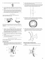
Choose your exhaust installation type
Recommended exhaust installations
Typical installations vent the dryer from the rear of the dryer.
Other installations are possible.
A .......
B
..................................F
.......................................G
A. Dryer
B. Elbow
C. Wall
D. Exhaust hood
E. Clamps
F. Rigid metal or flexible metal vent
G. Vent length necessary to connect elbows
H. Exhaust outlet
Optional exhaust installations
This dryer can be converted to exhaust out the right side, left side
or through the bottom. If you prefer, you may contact your local
dealer to have the dryer converted.
Fire Hazard
Cover unused exhaust holes with one of the
following kits:
279818 (white)
279820 (black)
Contact your local dealer.
Failure to follow these instructions can result in death,
fire, electrical shock, or serious injury.
A B
A. Standard rear offset exhaust installation
B. Left or right side exhaust installation
C. Bottom exhaust installation
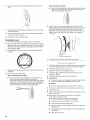
Alternate installations for close clearances
Venting systems come in many varieties. Select the type best for
your installation, Two close-clearance installations are shown.
Refer to the manufacturer's instructions.
I "_?jzz_z_
i "i.... i i
i i
i ii
I u
u
A B
A. Over-the-top installation (also available with one
offset elbow)
B. Periscope installation
15

NOTE: The following kits for close clearance alternate
installations are available for purchase. Please see the
"Assistance or Service" section of this manual to order.
• Over-the-Top Installation:
Part Number 4396028
• Periscope Installation (For use with dryer vent to wall vent
mismatch):
Part Number 4396037 - 0" (0 cm) to 18" (45.72 cm) mismatch
Part Number 4396011 - 18" (45.72 cm) to 29" (73.66 cm)
mismatch
Part Number 4396014 - 29" (73.66 cm) to 50" (127 cm)
mismatch
Special provisions for mobile home installations
The exhaust vent must be securely fastened to a noncombustible
portion of the mobile home structure and must not terminate
beneath the mobile home. Terminate the exhaust vent outside.
Vent system chart
NOTE: Side and bottom exhaust installations have a 90° turn
inside the dryer. To determine maximum exhaust length, add one
90° turn to the chart.
Number of Type of Box or Angled
90° turns vent Iouvered hoods
or elbows hoods
0 Rigid metal 64 ft (20 m) 58 ft (17.7 m)
Flexible metal 36 ft (11 m) 28 ft (8.5 m)
1 Rigid metal 54 ft (16.5 m) 48 ft (14.6 m)
Flexible metal 31 ft (9.4 m) 23 ft (7 m)
2 Rigid metal 44 ft (13.4 m) 38 ft (11.6 m)
Flexible metal 27 ft (8.2 m) 19 ft (5.8 m)
3 Rigid metal 35 ft (10.7 m) 29 ft (8.8 m)
Flexible metal 25 ft (7.6 m) 17 ft (5.2 m)
4 Rigid metal 27 ft (8.2 m) 21 ft (6.4 m)
Flexible metal 23 ft (7 m) 15 ft (4.6 m)
Determine vent path
• Select the route that will provide the straightest and most
direct path outdoors.
• Plan the installation to use the fewest number of elbows and
turns.
• When using elbows or making turns, allow as much room as
possible.
• Bend vent gradually to avoid kinking.
• Use the fewest 90 ° turns possible.
Determine vent length and elbows needed for best
drying performance
• Use the following Vent system chart to determine type of vent
material and hood combinations acceptable to use.
NOTE: Do not use vent runs longer than those specified in
the Vent system chart. Exhaust systems longer than those
specified will:
• Shorten the life of the dryer.
• Reduce performance, resulting in longer drying times and
increased energy usage.
The Vent system chart provides venting requirements that will
help to achieve the best drying performance.
1.
2.
3.
Install exhaust hood. Use caulking compound to seal exterior
wall opening around exhaust hood.
Connect vent to exhaust hood. Vent must fit inside exhaust
hood. Secure vent to exhaust hood with 4" (10.2 cm) clamp.
Run vent to dryer location. Use the straightest path possible.
See "Determine vent path" in "Plan Vent System." Avoid 90°
turns. Use clamps to seal all joints. Do not use duct tape,
screws or other fastening devices that extend into the interior
of the vent to secure vent.
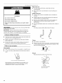
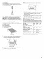
Excessive Weight Hazard
Use two or more people to move and install dryer.
Failure to do so can result in back or other injury.
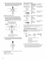
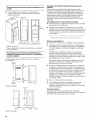
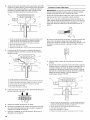
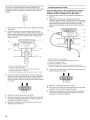
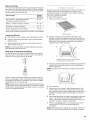
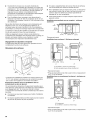
1. To protect the floor, use a large flat piece of cardboard from
the dryer carton. Place cardboard under the entire back edge
of the dryer.
2. Firmly grasp the body of the dryer (not the console panel).
Gently lay the dryer on the cardboard. See illustration.
16

3=
Examine the leveling legs. Find the diamond marking.
4. Screw the legs into the leg holes by hand. Use a wrench to
finish turning the legs until the diamond marking is no longer
visible.
5. Place a carton corner post from dryer packaging under each
of the 2 dryer back corners. Stand the dryer up. Slide the
dryer on the corner posts until it is close to its final location.
Leave enough room to connect the exhaust vent.
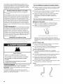
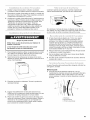
2. Lift and pull forward on the door so that the keyhole clears
the screw head. Remove the door.
3. Lay the dryer door on a flat, protected surface with the inside
door assembly facing up. Remove the last screw from Step 1.
Remove the 2 screws holding the handle to the door.
Check the levelness of the dryer. Check levelness first
side to side, then front to back.
4. Remove the 6 screws to release the outer door assembly
from the inner door assembly (see illustration). It is important
that you remove only the 6 indicated screws.
If the dryer is not level, prop up the dryer using a wood block.
Use a wrench to adjust the legs up or down and check again for
levelness.
1. Using a 4" (10.2 cm) clamp, connect vent to exhaust outlet in
dryer. If connecting to existing vent, make sure the vent is
clean. The dryer vent must fit over the dryer exhaust outlet
and inside the exhaust hood. Check that the vent is secured
to exhaust hood with a 4" (10.2 cm) clamp.
2. Move dryer into its final location. Do not crush or kink vent.
3. (On gas models) Check that there are no kinks in the flexible
gas line.
4. Once the exhaust vent connection is made, remove the
corner posts and cardboard.
5=
Lift the inner door assembly off of the outer door assembly.
Unsnap the handle from the outer door assembly, move it to
the other side, and snap in. Set the outer door assembly
aside.
\
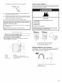
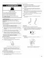
You can change your door swing from a right-side opening to a
left-side opening, if desired.
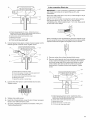
Remove the door
1. Open the dryer door. Remove the 4 screws that hold the door
hinge on the front panel of the dryer. Loosen, but do not
remove, the screw with the top keyhole opening last (second
from the top).
A. Dryer
B. Do not remove.
C. Dryer door
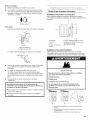
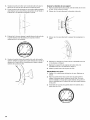
Reverse the hinge and hinge bracket
1. Place the inner door, screw head side up, on the work
surface.
2. Remove the 4 screws that hold the hinge to the door.
/
° ,
17

3. Remove the 2 screws that hold the handle bracket to the
door.
\
4. Move hinge to the other side and reattach with the 4 screws
removed in Step 2.
5. Move handle bracket to the other side and reattach with the
2 screws removed in Step 3.
6. Set the inner door assembly aside.
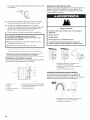
Reinstalling the door
1. Check for fingerprints on the glass. Clean if necessary.
2. Place the inner door assembly into the outer door assembly.
Align the hinge in the opening on the side. To fit correctly, the
inside door assembly edge is completely inside the outside
door assembly edge.
3. Reassemble the inner and outer door assemblies with the
6 screws.
6.
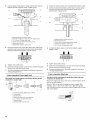
Style 2: Remove the label.
• Peel off the label located on the opposite side of the door
opening covering the hinge mounting holes. Apply the
label over the original hinge holes.
Insert a screw in the second opening from the top of the
hinge opening and partially tighten. Hang the door by placing
the top hinge keyhole over the second screw head and
tighten the screw. By putting this screw in first, the door will
hang in place while you insert and tighten the remaining
4 screws.
\
A. Dryer door
B. Dryer
C. Insert this screw first.
7. Close the door and check that it latches securely.
4. Replace the 2 handle screws for the door handle of the door
assembly.
5. Remove the plug strip or label.
Style 1: Remove the plug strip.
Use a small flat-blade screwdriver to remove the plug
strip in the door opening. Slide the head of the
screwdriver under the top portion of the plug strip, being
certain not to scratch the dryer surface. Lift up. Repeat in
the middle and at the bottom. Remove the plug strip in
the door opening and insert in the opposite side.
2.
3.
4.
5.
6.
7.
8.
g.
10.
Check that all parts are now installed. If there is an extra part,
go back through the steps to see which step was skipped.
Check that you have all of your tools.
Dispose of/recycle all packaging materials.
Check the dryer's final location. Be sure the vent is not
crushed or kinked.
Check that the dryer is level. See "Level Dryer."
In the U.S.A.
• For power supply cord installation, plug into a grounded
outlet. For direct wire installation, turn on power.
In Canada
• Plug into a grounded 4 prong outlet. Turn on power.
Remove any protective film or tape remaining on the dryer.
Read "Dryer Use."
Wipe the dryer drum interior thoroughly with a damp cloth to
remove any dust.
Set the dryer on a full heat cycle (not an air cycle) for
20 minutes and start the dryer.
If the dryer will not start, check the following:
• Controls are set in a running or "On" position.
• Start button has been pushed firmly.
• Dryer is plugged into a grounded outlet and/or electrical
supply is on.
• Household fuse is intact and tight, or circuit breaker has
not tripped.
• Dryer door is closed.
18

11. When the dryer has been running for 5 minutes, open the
dryer door and feel for heat. Ifyou feel heat, cancel cycle and
close the door.
If you do not feel heat, turn off the dryer and check the
following:
• There may be 2 household fuses or circuit breakers for
the dryer. Check that both fuses are intact and tight, or
that both circuit breakers have not tripped. If there is still
no heat, contact a qualified technician.
NOTE: You may notice a burning odor when the dryer is first
heated. This odor is common when the heating element is first
used. The odor will go away.
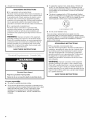
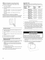
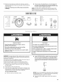
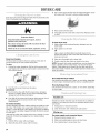
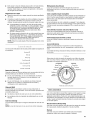
DRYER USE
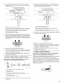
F
CONTROLON O AUTOMATIC MANUAL EstlmatedTirne ¢O High
Heavy Duty CYCL_$ Timed Dry Rema n_ng IO Medium
Wet 0 Casu Rapid Dry Less Air On(y Off
m ooo0 ,oj o o o o
Cycle Complete O
DRYNESS TEMP EXTRA CYCLE
Extra Care O LEVEL CARE END
SIGNAL
Control Locked O Hold {or 3
seconds to
_ock / un!ock Pause
control
%. j
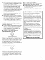
Explosion Hazard
Keep flammable materials and vapors, such as
gasoline, away from dryer.
Do not dry anything that has ever had anything
flammable on it (even after washing).
Failure to follow these instructions can result in death,
explosion, or fire.
Fire Hazard
No washer can completely remove oil.
Do not dry anything that has ever had any type of oil on
it (including cooking oils).
items containing foam, rubber, or plastic must be dried
on a clothesline or by using an Air Cycle.
Failure to follow these instructions can result in death
or fire.
WARNING: To reduce the risk of fire, electric shock, or injury to
persons, read the IMPORTANT SAFETY INSTRUCTIONS before
operating this appliance.
This manual covers several different models. Your dryer may not
have all of the cycles and features described.
Follow these basic steps to start your dryer. Please refer to
specific sections of this manual for more detailed information.
1. Clean lint screen before or after each cycle. See "Cleaning
the Lint Screen."
2. Place laundry in dryer and shut door.
3. Rotate the dial to select either an Automatic or Manual Cycle
then press the CONTROL ON button. The preset settings and
drying time for the cycle chosen will be displayed.
To use an Automatic Cycle
• Point the dial to an Automatic Cycle.
Select DRYNESS LEVEL to adjust how dry you want the
load to be. The time displayed is an estimated length of
the cycle based on the Dryness Level selected. As the
cycle runs, the control senses the dryness of the load and
adjusts the time automatically for the selected Dryness
Level.
I ore
Less
O
DRYNESS
LEVEL
NOTE: Time is not adjustable for Automatic Cycles. Pressing
the Manual Dry Time (- or +) buttons will cause a triple beep,
indicating that the time cannot be changed.
• Press the EXTRA CARE feature button if this option is
desi red.
19

• Press the CYCLE END SIGNAL button to set signal
volume to desired level.
• Press and hold HOLD TO START button until dryer starts
(about 1second).
Once an Automatic cycle has started, the Extra Care feature
and the Cycle End Signal level can be adjusted. Press the
OFF button twice to stop the dryer and clear the settings,
allowing you to select another cycle and Dryness Level.
How Automatic Cycles Work
This feature improves drying performance with Auto Moisture
Sensing Plus, which advances the cycle as moisture is
extracted from clothing. A thermistor (electronic temperature
sensor) and moisture sensing strips in the dryer drum help
measure the amount of moisture in the clothes as they
tumble. An electronic control determines the load type to help
save time, avoid overdrying, and increase the accuracy of the
end dryness level. After the first 5 minutes of an automatic
cycle, the estimated time display will adjust based on the
approximate load size, cycle, dryness level selected and
amount of moisture left in the clothes. When the clothes have
reached approximately 80% of the dryness level selected, the
estimated time display will adjust again, showing the final
drying time. Auto Moisture Sensing Plus takes the guesswork
out of drying time and enhances fabric care.
To use a Manual Cycle
• Rotate the dial to select a Manual Cycle.
Press MANUAL DRY TIME (- or +) buttons until the desired
drying time is displayed. Tap - or + and the time will change
by 1-minute intervals. Press and hold - or + and the time will
change by 5-minute intervals. The initial time displayed is the
actual drying time.
NOTE: The Manual Dry Time feature can be used only with
Manual Cycles.
• Press TEMP until the desired temperature illuminates.
NOTE: Pressing the Dryness Level button will cause the triple
beep indicating that this option is not selectable. Also, a
Dryness Level is not indicated.
• Press the EXTRA CARE feature button if this option is
desired.
• Press the CYCLE END SIGNAL button to set volume to
desired level.
• Press and hold HOLD TO START button until dryer starts
(about 1second).
While a Manual Cycle is running, you can change the settings
for Time, Temperature, the Extra Care feature, and the Cycle
End Signal. Press the OFF button twice to stop the dryer and
clear the settings, allowing you to select another cycle.
To stop your dryer at anytime
Press OFFtwice or open the door.
To pause the dryer at any time
Open the door or press OFF once.
To restart the dryer
Close the door and press and hold HOLD TO START button until
dryer starts.
NOTE: Drying will continue from where the cycle was interrupted
if you close the door and press Start within 5 minutes. Ifthe cycle
is interrupted for more than 5 minutes, the dryer will shut off.
Select new cycle settings before restarting the dryer.
This feature allows you to lock your settings to avoid unintended
use of the dryer. You can also use the Control Locked feature to
avoid unintended cycle or option changes during dryer operation.
To enable the Control Locked feature when dryer is
running:
Press and hold the CYCLE END SIGNAL button for 3 seconds.
The control is locked when a single beep is heard and the Control
Locked status light is on.
• When the dryer is off, it is not necessary to press the Control
On button before activating the Control Locked feature.
To unlock:
Press and hold the CYCLE END SIGNAL button for 3 seconds to
turn this feature off.
NOTE: When the dryer is running and Control Locked is on, the
dryer can be stopped by pressing the Off button, but can't be
restarted until the control is unlocked.
Select the correct cycle and dryness level or temperature for your
load. If an Automatic Cycle is running, the display shows the
estimated cycle time when your dryer is automatically sensing
the dryness level of your load. If a Manual Cycle is running, the
display shows the exact number of minutes remaining in the
cycle.
Cool Down tumbles the load without heat during the last few
minutes of all cycles. Cool Down makes the loads easier to
handle and reduces wrinkling. The length of the Cool Down
depends on the load size and dryness level.
Drying tips
• Follow care label directions when they are available.
• If desired, add a fabric softener sheet. Follow package
instructions.
• Remove the load from the dryer as soon as tumbling stops to
reduce wrinkling. This is especially important for permanent
press, knits and synthetic fabrics.
• Avoid drying heavy work clothes with lighter fabrics. This
could cause overdrying of lighter fabrics, leading to increased
shrinking or wrinkling.
Cycle tips
• Dry most loads using the preset cycle settings.
• Refer to the Automatic or Manual Preset Cycle Settings chart
(in the "Cycles" section) for a guide to drying various loads.
Drying temperature and Dryness Level are preset when
you choose an Automatic Cycle. You can choose a
different dryness level, depending on your load by
pressing the DRYNESS LEVEL button to select MORE or
LESS.
• If you wish to adjust the cycle length of a Manual Cycle,
you must press the MANUAL DRY TIME (- or +) buttons.
Adjust the temperature of a Manual Cycle by pressing
TEMP until the desired temperature is selected.
NOTE: You cannot choose a Dryness Level with Manual
Cycles.
20
La page est en cours de chargement...
La page est en cours de chargement...
La page est en cours de chargement...
La page est en cours de chargement...
La page est en cours de chargement...
La page est en cours de chargement...
La page est en cours de chargement...
La page est en cours de chargement...
La page est en cours de chargement...
La page est en cours de chargement...
La page est en cours de chargement...
La page est en cours de chargement...
La page est en cours de chargement...
La page est en cours de chargement...
La page est en cours de chargement...
La page est en cours de chargement...
La page est en cours de chargement...
La page est en cours de chargement...
La page est en cours de chargement...
La page est en cours de chargement...
La page est en cours de chargement...
La page est en cours de chargement...
La page est en cours de chargement...
La page est en cours de chargement...
La page est en cours de chargement...
La page est en cours de chargement...
La page est en cours de chargement...
La page est en cours de chargement...
La page est en cours de chargement...
La page est en cours de chargement...
La page est en cours de chargement...
La page est en cours de chargement...
La page est en cours de chargement...
La page est en cours de chargement...
La page est en cours de chargement...
La page est en cours de chargement...
La page est en cours de chargement...
La page est en cours de chargement...
La page est en cours de chargement...
La page est en cours de chargement...
La page est en cours de chargement...
La page est en cours de chargement...
La page est en cours de chargement...
La page est en cours de chargement...
La page est en cours de chargement...
La page est en cours de chargement...
La page est en cours de chargement...
La page est en cours de chargement...
La page est en cours de chargement...
La page est en cours de chargement...
La page est en cours de chargement...
La page est en cours de chargement...
La page est en cours de chargement...
La page est en cours de chargement...
La page est en cours de chargement...
La page est en cours de chargement...
-
 1
1
-
 2
2
-
 3
3
-
 4
4
-
 5
5
-
 6
6
-
 7
7
-
 8
8
-
 9
9
-
 10
10
-
 11
11
-
 12
12
-
 13
13
-
 14
14
-
 15
15
-
 16
16
-
 17
17
-
 18
18
-
 19
19
-
 20
20
-
 21
21
-
 22
22
-
 23
23
-
 24
24
-
 25
25
-
 26
26
-
 27
27
-
 28
28
-
 29
29
-
 30
30
-
 31
31
-
 32
32
-
 33
33
-
 34
34
-
 35
35
-
 36
36
-
 37
37
-
 38
38
-
 39
39
-
 40
40
-
 41
41
-
 42
42
-
 43
43
-
 44
44
-
 45
45
-
 46
46
-
 47
47
-
 48
48
-
 49
49
-
 50
50
-
 51
51
-
 52
52
-
 53
53
-
 54
54
-
 55
55
-
 56
56
-
 57
57
-
 58
58
-
 59
59
-
 60
60
-
 61
61
-
 62
62
-
 63
63
-
 64
64
-
 65
65
-
 66
66
-
 67
67
-
 68
68
-
 69
69
-
 70
70
-
 71
71
-
 72
72
-
 73
73
-
 74
74
-
 75
75
-
 76
76


Maytag MED9600SQ0 Manuel utilisateur
- Catégorie
- Laveuses sécheuses
- Taper
- Manuel utilisateur
dans d''autres langues
- English: Maytag MED9600SQ0 User manual
- español: Maytag MED9600SQ0 Manual de usuario