Swing-N-Slide Playsets WS 5007 Mode d'emploi
- Taper
- Mode d'emploi

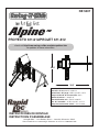
Alpine
TM
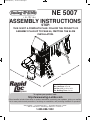
NE 5007
Swing•N•Slide • 1212 Barberry Drive • Janesville, Wisconsin 53545
Visit our web site at: www.swing-n-slide.com or call us at 1-800-888-1232
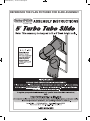
ASSEMBLY INSTRUCTIONS
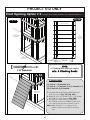
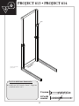
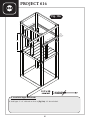
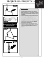
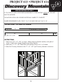
PROJECT 611& 612
check out http://www.swing-n-slide.com/planupdates.htm
for updates to these instructions.
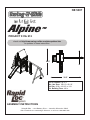
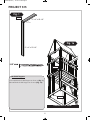
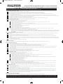
No. of Children: Up to 11
Min. Use Zone: 28-1/2' x 30-1/2'
Set Dim. 13'W x 18-1/2'L x 11'H
Est. Building Time: 4-8 hr.
28.5'
30.5'

2
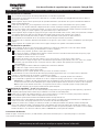
Important!
Additional Safety Instructions for all Swing-N-Slide Playground Equipment.
Save this instruction sheet in the event the manufacturer needs to be contacted.
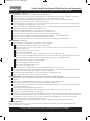
Safety Checklist for Swing-N-Slide Accessories
Installation Safety – Have You:
Consulted the assembly instructions supplied with your particular model?
Noted this accessory is to be used only on Swing•N•Slide approved designs? (Do not alter its design or add/remove components.)
Made sure all hardware is tightened securely? (Supplied bolt covers must also be fastened securely.)
Using a hacksaw, cut off all protruding threaded ends of bolts and other fasteners and remove any sharp edges with
a metal file as needed?
Placed the equipment on level ground, not less than six feet (1.8 meters) from any structure or obstruction such as a fence, garage,
house, overhanging branches, laundry lines, or electrical wires?
Made sure home playground equipment is not installed over concrete, asphalt, packed earth or any other hard surface? (A fall onto
a hard surface can result in serious injury to the equipment user.)
Verified that suspended climbing ropes, chain,or cable are secured at both ends?
Consulted in assembly instructions of your particular model for minimum use zones?
Followed all anchoring and shock absorbing surfacing requirements later in this guide as they apply?
Made sure not to allow children to use equipment until it is properly installed?
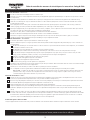
Operating Safety – Have You:
Determined that on-site adult supervision is provided for children of all ages?
Warned children the following before allowing them to use the equipment?
Not to walk close to, in front of, behind or between moving items.
Not to twist swing or any other accessory chains or ropes or loop them over the top support bar since this will reduce the
strength of chain or rope.
Not to swing empty seats or other accessories.
Be sure to sit in the center of the swing seat and other accessories with full weight on the seat.
Not to attach items to the playground equipment that are not specifically designed for use with the equipment such as but not
limited to, jump ropes, clotheslines, pet leashes, cables and chain. They may cause a strangulation hazard.
Not to use equipment in a manner other than intended.
Not to get off equipment while it is in motion.
Not to climb on the equipment when it is wet.
Determined that only one child per planned occupant seat should be allowed on this set at one time.
Determined children must be dressed appropriately for play. Avoid clothing with draw strings and loose fitting clothes which
could become entangled or snagged on equipment.
Determined that suspended climbing ropes, chain, or cable cannot be looped back upon itself.
Read and understood the following warning regarding the use of two and four passenger lawn swings?
Warning: Lawn Swings are designed for use by children over two years of age. Use by children under the age of two can result
in entrapment between the seats and back areas. Never place children in a rearward facing position or with legs between the
seat and backrest because the child’
s body may pass through the opening causing entrapment of the child’s head.
Safety Maintenance – Have You Determined to:
Check all nuts and bolts twice monthly during the usage season for tightness and tighten as required? (It is
particularly important that this procedure be followed at the beginning of each season.)
To prevent the deterioration of materials, remove plastic swing seats and other plastic accessories and take indoors? (Do not
use when the temperature drops below 0° F.)
Oil all metallic moving parts monthly during usage period?
Check all hardware and equipment for sharp edges twice monthly during usage season? (Replace when
necessary. It is especially important to do this at the beginning of each new season.)
Check swing seats, chains, ropes and cables monthly during usage season for evidence of deterioration? Severe rusting or excessive
wear, especially near the top swing hanger or at the seat connection are evidence of chain deterioration. Cracks in the protective plastic
sleeve or seat itself are also signs of deterioration. If any of these conditions exist, call 1-800-888-1232 to order replacement accessories.
Disposal Instructions
When the equipment is taken out of service, it must be disassembled and disposed of in such a way that no unreasonable hazards
will exist at the time the set is discarded.
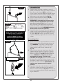
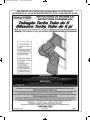
Observing the following statements and warnings reduces the likelihood of serious or fatal injury
R

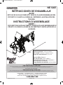
SAFETY INSTRUCTIONS
INSTRUCCIONES DE SEGURIDAD
INSTRUCTIONS CONCERNANT LA SÉCURITÉ
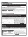
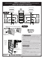
REQUIRED SAFETY INSTALLATION INSTRUCTIONS
• Once the unit is completely assembled and before children are allowed to play on it, proper shock-absorbing surfacing material
must be installed. This may be accomplished by using loose-fill materials at a sufficient depth. The Consumer Product Safety Commission
“Handbook for Public Playground Safety” lists the following materials and required depths that are suf
ficient for home/residential application.
For fall height protection up to 9 ft. (2.742m) [recommended for Swing•N•Slide kits]:
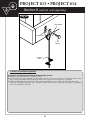
When properly installed, shock absorbing material will completely
cover the horizontal baseboards on climbing units. This protective
surfacing must extend a minimum of 6 ft. (1.828m) in all directions
from the perimeter of the equipment or from the outermost edges of
any component. For example, a slide extending beyond the platform
must have protective surfacing at least 6 ft. (1.828m) out from both
sides as well as the end. For swings, the protective surface must
extend at least 14 ft.
out from both the back and front of the swing
when the swing is in its rest position.
IMPORTANT!
This product is intended for single family residential use only and not intended for use in any public
setting. Placement in any public setting constitutes a misuse of this product.
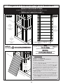
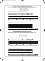
LOOSE FILL MATERIAL REQUIRED DEPTH
1
INCH (mm)
(UNCOMPRESSED)
Wood Mulch 9" (229mm)
Double Shredded Bark Mulch
9" (229mm)
Uniform Wood Chips 12" (305mm)
Fine Sand 12" (305mm)
Fine Gravel 12" (305mm)
1 These depths were derived from the CPSC Handbook. Swing•N•Slide
has not done independent tests to determine these required depths.
LʼUTILISATION DANS UN ENDROIT PUBLIC CONSTITUE UN USAGE ABUSIF DU PRODUIT.
• Lorsque lʼunité est entiŹrement assemblée, un matériau de protection amortisseur doit źtre installé sur le sol avant de permettre aux
enfants de sʼamuser. Des matériaux particulaires dʼune épaisseur suffisante peuvent źtre utilisés ą cette fin. Le guide américain intitulé « Handbook
for Public Playground Safety » rédigé par la Consumer Product Safety Commission (CPSC) des États-Unis recommande une liste de matériaux et
spécifie lʼépaisseur requise pour un usage résidentiel. Protection contre les chutes dʼune hauteur de 9 pieds (2,742 m) [recommandation pour les
unités Swing•N•Slide] :
Pour que lʼinstallation soit adéquate, le matériau amortisseur doit
recouvrir entiŹrement la base horizontale des unités dʼescalade. Un
matériau de protection doit entourer lʼinstallation sur une surface dʼau
moins 1,828 m (6 pieds) ą partir du pourtour de lʼunité ou des
composants les plus éloignés. Par exemple, une glissoire qui se
prolonge au-delą de la plate-forme doit źtre pourvue dʼune surface de
protection dʼau moins 1,828 m (6 pieds) de chaque côté ainsi quʼą
lʼextrémité. En ce qui concerne les balanćoires, la zone de protection doit
couvrir au moins 14 pi (6 m)
autant devant que derriŹre la balanćoire
lorsque celle-ci est immobile.
IMPORTANT!
Ce produit est conću uniquement pour un usage résidentiel. Il ne saurait aucunement convenir aux
installations publiques.
MATÉRIAUX PARTICULAIRES ÉPAISSEUR RECOMMANDÉE
1
EN PO (mm) (NON COMPRIMÉ)
Paillis de bois 9 po (229mm)
Paillis dʼécorce filamentée
9 po (229mm)
Copeaux de bois uniformes 12 po (305mm)
Sable fin 12 po (305mm)
Gravier fin 12 po (305mm)
1 Ces valeurs sont tirées du guide de la CPSC. Les unités Swing•N•Slide
nʼont pas fait lʼobjet dʼessais indépendants afin de déterminer lʼépaisseur
recommandée des matériaux.
INSTRUCCIONES REQUERIDAS PARA LA INSTALACIÓN CON SEGURIDAD
• Una vez que se haya armado la unidad completamente y antes que se permita a los niĖos que la usen, se debe instalar un material
que amortigüe para la superficie del suelo. Esto se puede conseguir usando materiales que llenen flojamente a una profundidad suficiente.
El “Folleto para la Seguridad Pública en Campos de Recreo” de la Comisión de Seguridad de Producto al Cliente, permite los siguientes
materiales y las profundidades requeridas que sean lo suficiente para una aplicación en situaciones de residencias. Para protección contra
caídas se necesita hasta 9 pies (2,742m) [recomendadas para los conjuntos Swing•N•Slide]:
Cuando se instale apropiadamente, el material que amortigüe
completamente cubrirá la base horizontal de las unidades de trepar.
Esta superficie protectora debe extenderse un mínimo de 6 pies
(1,828m) en todas las direcciones desde el perímetro del equipo, o de
los bordes más salientes de cualquier componente. Por ejemplo, un
tobogán que se extiende más allá de la plataforma debe tener una
superficie protectora de por lo menos 6 pies (1,828m) más allá de
ambos lados, al igual que desde el extremo. Para columpios, la
superficie protectora debe extenderse por lo menos 14 pies
más allá
de ambos,
de la parte de atrás, y la parte frontal del columpio, cuando
el columpio esté en una posición neutra.
ŃIMPORTANTE!
Este producto es para ser usado por una sola familia en uso residential y no para usarse en
ningún lugar público. El ubicarlo en cualquier lugar público constituye mal uso de este producto.
MATERIAL DE APLICACIÓN FLOJA PROFUNDIDAD REQUERIDA
1
PULGADA
mm (SIN SER COMPRIMIDA)
Viruta de madera 9" (229mm)
Viruta trizada de corteza de árbol 9" (229mm)
Trozos pequeĖos uniformes
de madera 12" (305mm)
Arena fina 12" (305mm)
Grava fina 12" (305mm)
1
Estas profundidades fueron derivadas del folleto CPSC. Swing
•
N
•
Slide no
ha hecho pruebas independientes para determinar las requeridas profundidas.
3

4
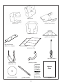
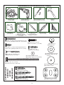
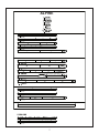
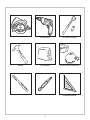
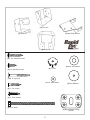
(6) 1-1/4'' screws
(2) 5/16'' flat washers
(4) Bottom Beam Clamps
(slotted)
(6) Tarp Washers
(4) 1/4'' flat washers
(6) T- nuts
(2) 1/2'' panhead screws
(2) 1-3/4'' panhead screws
(2) 5-1/2'' Bolts
(4) 1'' Truss Screws
(108) 2" lag screw
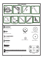
CIRCULAR SAW
ELECTRIC DRILL
1/2" SOCKET & WRENCH
HAMMER
TAPE MEASURE
SAFETY GLASSES
& DUST MASK
3/8" DRILL BIT (6'' Min.)
PHILLIPS BIT
CARPENTER'S SQUARE
TOOLS REQUIRED

5
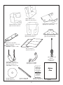
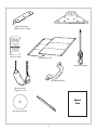
(2) Swing Seats
weight limit: 115 lbs.
(4) Swing Hangers
THIS PRODUCT IS
INTENDED FOR USE
BY CHILDREN FROM
AGES 2-10 YEARS
For Home / Residential
Use ONLY
1212 Barberry Drive
Janesville, WI 53545
1-800-888-1232
www.swing-n-slide.com
PROCESS
BLACK
PANTONE "NEWCO RED"
R
R
R
(1) Name Plate
(10) Step Brackets
Note: (5 Left, 5 Right)
(1) Plan
(2) Safety Handles
(1) T30 Torx® Bit
(2) EZ Frame Brackets
(1) Instructional DVD
Alpine
Plan
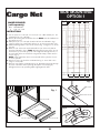
(1) Multicolor Tarp
(2) Shelf-Loc
(10) Cup-Loc
(6) Wrap-Loc
(2) Split Beam bracket

6
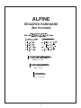
(287) 2-1/2'' screws
(56) 2'' screws
'
e
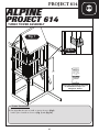
ALPINE
REQUIRED HARDWARE
(Not Included)
(64) 1-1/4'' screws

7
ALPINE

8
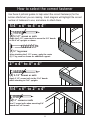
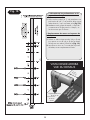
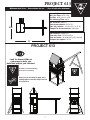
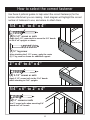
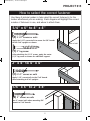
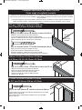
(3) 2-1/2'' screws or nails
Apply 2 1/2" screws/nails to the 2"x4" boards
when attaching to 4"x4" uprights.
(4) 2-1/2'' screws or nails
(2) 2'' screws or nails
Use 2" screws/nails when mounting 5/4"
boards to 2"x4" boards.
Apply the 2-1/2" screws/nails to secure the 5/4" boards
to the 4"x4" uprights as shown.
How to select the correct fastener
Use these 3 pictorial guides to help select the correct fastener(s) for the
lumber attachment you are making. Each diagram will highlight the correct
number of fasteners to use, and where to attach them.
Base of unit
5/4'' x 6'' to 4'' x 4''
2'' x 4'' to 4'' x 4''
5/4'' x 6'' to 2'' x 4''
(1) 2'' lag screw
After attaching the 2 1/2" screws, apply the center
(1) 2" lag screw as shown for additional support.

9
-
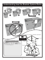
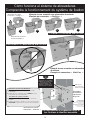
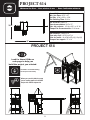
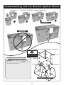
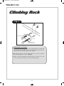
Understanding how the Bracket System Works
Cup-Loc
GAP
Introduction to the Bracket system
1. ALWAYS Use 2'' lag screws on all brackets.
2. Brackets ''clip'' to each other. NEVER position in
a non-interlocking position.
Top of bracket
Bottom of bracket
(Hole locations close to bottom)
Example of a Shelf-Loc bracket connection.
Wrap-Loc
Shelf-Loc Bracket
1
2
3
4
Wrap-Loc
CORRECT!
WRONG!
Brackets Clip Together
brackets NOT
interlocked!
Brackets
''clipped''
Example of a Cup-Loc bracket connection.
TOP
Look for ''TOP'' stamp on
bracket for correct orientation.

10
4'' x 4'' x 96''
(4)
2'' lag screws
43-1/4''
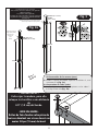
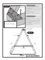
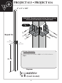
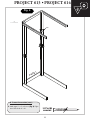
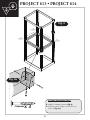
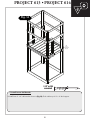
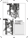
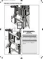
A. Frame Construction
1. Measure and position brackets on (4) 4'' x 4'' x 96’’ as shown in (Fig.1).
x 8 (4 each bracket)
Repeat 4x
2'' Lag screw
Fig. 1
REMEMBER: Brackets are inter-locking. Cup-loc will clip
and secure into the Wrap-Loc as shown below.
GAP

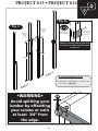
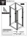
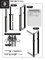
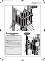
11
82-1/2''
82-1/2''
GA
P (this side)
GAP (this side)
Wrap-Loc opening must be positioned
as shown on in these locations below
for later use. (See page 24)
Use a 2’’ lag screw
to hold bracket in
place for later use.
Look for ‘’TOP’’
stamp on brackets
while installing.
TOP
GAP on
this side
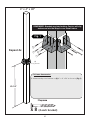
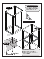
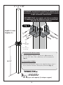
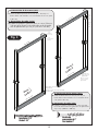
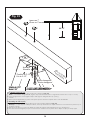
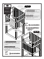
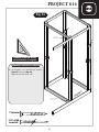
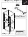
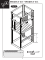
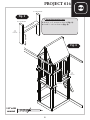
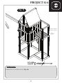
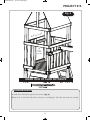
A. Frame Construction (cont.)
2. Install upper Wrap-Brackets to Frame 2 as shown in (Fig. 2a)
Fig. 2a
Fig. 2
lag screw to
hold in place
(back)
lag screw to
hold in place
(back)
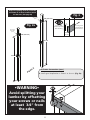
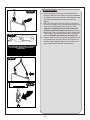
•WARNING•
Avoid splitting your
lumber by offsetting
your screws or nails
at least 3/4’’ from
the edge.
Frame 2

12
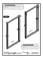
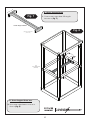
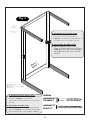
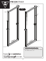
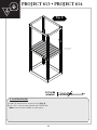
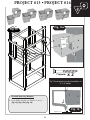
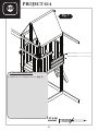
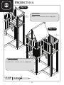
A. Frame Construction (cont.)
3. Install upper 2'' x 4'' boards. Edges are to be flush
with 4'' x 4’’s.
Fig. 3
2'' x 4'' x 55''
2'' x 4'' x 55''
5/4'' x 6'' x 55''
5/4'' x 6'' x 55''
Frame 1
Frame 2
(3)
2-1/2'' screws/nails
(4) 2-1/2'' screws/nails
(1) Lag Screw
(4) 2-1/2'' screws/nails
(1) Lag Screw
(3) 2-1/2''
screws/
nails
2'' Lag screw
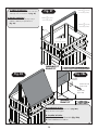
A. Frame Construction (cont.)
4. Install lower 5/4'' boards. Edges are to be flush
with 4'' x 4’’s.
2-1/2'' or 10D
screw/nail

13
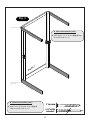
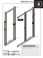
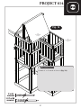
Fig. 4
2'' x 4'' x 43''
5/4'' x 6'' x 43''
2'' x 4'' x 43''
5/4'' x 6'' x 43''
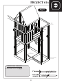
A. Frame Construction (cont.)
5. Attach upper 2'' x 4'' as shown in (Fig. 4). Edges
are to be flush with 4’’ x 4’’s.
A. Frame Construction (cont.)
6. Attach lower 5/4'' boards as shown in (Fig. 4).
Edges are to be flush with 4’’ x 4’’s.
(3) 2-1/2'' screws/nails
(4) 2-1/2'' screws/nails
(1) Lag Screw
2'' Lag screw
Frame 1
2-1/2'' or 10D
screw/nail

14
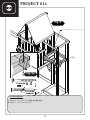
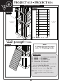
Fig. 5
(4) 4'' x 4'' x 35-1/2''
(6)
2'' lag screws
(3 each Cup-Loc)
(3) 2-1/2''
screws/nails
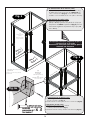
A. Frame Construction (cont.)
7. Secure upper 2'' x 4'' and lower 5/4''
boards to Frame 2 as shown in (Fig. 5).
Edges are to be flush with 4’
’ x 4’’s.
2'' Lag screw
(4) 2-1/2'' screws/nails
(1) Lag Screw
x 3
Double check to make
sure structure is square
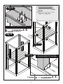
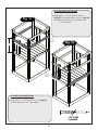
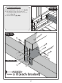
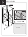
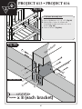
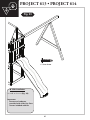
A. Frame Construction (cont.)
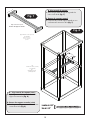
8. Install 4'' x 4'' beams as shown in (Fig. 6).
9. Install lag screws at each corner location as
shown in (Fig. 6a)
Fig. 6
Fig. 6a
4'' x 4'' x 47-1/2''
4'' x 4'' x 47-1/2''
4'' x 4'' x 35-1/2''
4'' x 4'' x 35-1/2''
Frame 2
Frame 1

15
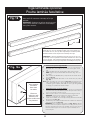
Fig. 8
Fig. 7
2'' x 4'' x 12''
2'' x 4'' x 45''
2'' x 4'' x 12''
(6)
2-1/2'' screws/nails
(each side)
Center
(2) 2-1/2'' screws/nails
(each side)
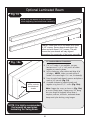
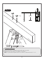
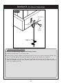
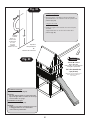
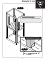
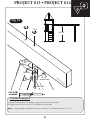
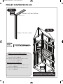
B. Center Support Beam cont.
2. Secure center support beam to structure as
shown in (Fig. 8).
B. Center Support Beam
1. Construct center support beam following the
instructions in (Fig. 7).
Center Support Beam
17-1/4''
2-1/2'' or 10D
screw/nail

16
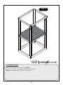
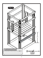
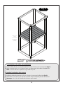
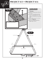
Fig. 9
(7) 5/4'' x 6'' x 43''
5/4'' x 6'' x 36''
2-1/2'' screws/nails
(2 per joint)
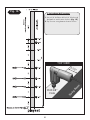
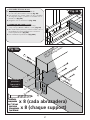
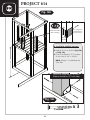
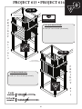
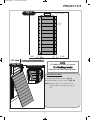
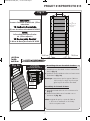
C. Install Deck Boards
1. Install 5/4'' deck boards to structure as shown (Fig. 9).
2. Use two 2-1/2'' screws/nails at center and each end of deck boards.
Note: Screws/Nails at center will attach to center support.
5/4'' x 6'' x 36''
2-1/2'' or 10D
screw/nail

17
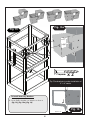
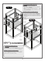
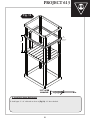
Fig. 10a
Fig. 11
Fig. 10
Fig. 11a
4'' x 4'' x 29-3/4''
9-1/8'' to edge
Secure 4''x4'' uprights with (3) 2'' lag screws
Bracket should be 1/2'' from edge
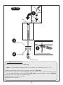
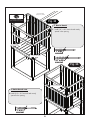
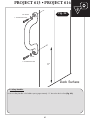
D. Install 4x4 Rail Supports
1. Install (2) Cup Loc as shown in (Fig.10),
(Fig 10a).
2. Install (2) 4'' x 4'' x 29-3/4'' as shown
in (Fig. 11) and (Fig. 11a).
4'' x 4'' x 29-3/4''
2'' Lag screw
x 3
2'' Lag screw
x 4
Install Cup Loc using (4) 2'' lag screws
9-1/8'' from post
1/2'' from edge
(both sides)

18
Fig. 12
Fig. 13
2'' x 4'' x 55''
2'' x 4'' x 55''
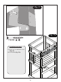
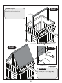
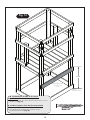
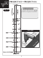
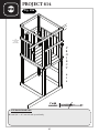
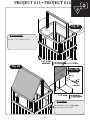
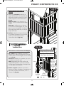
E. Install Upper Rail Boards
1. Install upper 2'' x 4'' rail boards as shown in
(Fig 12). 30’
’ above the deck as shown in (Fig 12).
Note: Measure from Top of 5/4'' board to top of
2'' x 4'' rail board.
F
. Install Lower Rail Boar
ds
1. Install lower 2’’ x 4’’ rail boards as shown in (Fig 13).
Flush with the top of 4’’ x 4’’ deck supports.
2'' x 4'' x 43''
30''
(3)
2-1/2''
screws/nails
per joint
(3)
2-1/2''
screws/nails
per joint
2'' x 4'' x 55''
2'' x 4'' x 16''
2'' x 4'' x 43''
2'' x 4'' x 16''
2'' x 4'' x 55''
2-1/2'' or 10D
screw/nail

19
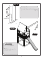
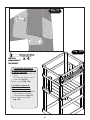
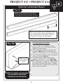
31-3/4''
bottom of base
Fig. 14
5/4'' x 6'' x 55''
(4)
2-1/2'' screws/nails
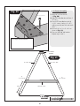
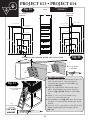
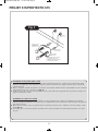
G. Install Pr
otective Barrier Board
1. Secure protective 5/4'' barrier board as shown in (Fig 14).
2-1/2'' or 10D
screw/nail

20
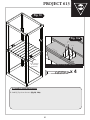
Fig. 15
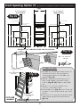
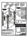
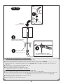
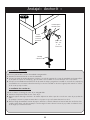
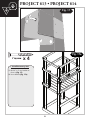
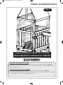
H. Install Accessory Brackets
1. Secure Shelf-Loc brackets onto Wrap-Loc as shown in
(Fig. 15), (Fig. 15a), (Fig. 16).
Fig. 15a
2'' Lag screw
x 2
Tip: Flex brackets to make installation of
4'' x 4'' easier
Fig. 16
Approx. 1/4''
La page est en cours de chargement...
La page est en cours de chargement...
La page est en cours de chargement...
La page est en cours de chargement...
La page est en cours de chargement...
La page est en cours de chargement...
La page est en cours de chargement...
La page est en cours de chargement...
La page est en cours de chargement...
La page est en cours de chargement...
La page est en cours de chargement...
La page est en cours de chargement...
La page est en cours de chargement...
La page est en cours de chargement...
La page est en cours de chargement...
La page est en cours de chargement...
La page est en cours de chargement...
La page est en cours de chargement...
La page est en cours de chargement...
La page est en cours de chargement...
La page est en cours de chargement...
La page est en cours de chargement...
La page est en cours de chargement...
La page est en cours de chargement...
La page est en cours de chargement...
La page est en cours de chargement...
La page est en cours de chargement...
La page est en cours de chargement...
La page est en cours de chargement...
La page est en cours de chargement...
La page est en cours de chargement...
La page est en cours de chargement...
La page est en cours de chargement...
La page est en cours de chargement...
La page est en cours de chargement...
La page est en cours de chargement...
La page est en cours de chargement...
La page est en cours de chargement...
La page est en cours de chargement...
La page est en cours de chargement...
La page est en cours de chargement...
La page est en cours de chargement...
La page est en cours de chargement...
La page est en cours de chargement...
La page est en cours de chargement...
La page est en cours de chargement...
La page est en cours de chargement...
La page est en cours de chargement...
La page est en cours de chargement...
La page est en cours de chargement...
La page est en cours de chargement...
La page est en cours de chargement...
La page est en cours de chargement...
La page est en cours de chargement...
La page est en cours de chargement...
La page est en cours de chargement...
La page est en cours de chargement...
La page est en cours de chargement...
La page est en cours de chargement...
La page est en cours de chargement...
La page est en cours de chargement...
La page est en cours de chargement...
La page est en cours de chargement...
La page est en cours de chargement...
La page est en cours de chargement...
La page est en cours de chargement...
La page est en cours de chargement...
La page est en cours de chargement...
La page est en cours de chargement...
La page est en cours de chargement...
La page est en cours de chargement...
La page est en cours de chargement...
La page est en cours de chargement...
La page est en cours de chargement...
La page est en cours de chargement...
La page est en cours de chargement...
La page est en cours de chargement...
La page est en cours de chargement...
La page est en cours de chargement...
La page est en cours de chargement...
La page est en cours de chargement...
La page est en cours de chargement...
La page est en cours de chargement...
La page est en cours de chargement...
La page est en cours de chargement...
La page est en cours de chargement...
La page est en cours de chargement...
La page est en cours de chargement...
La page est en cours de chargement...
La page est en cours de chargement...
La page est en cours de chargement...
La page est en cours de chargement...
La page est en cours de chargement...
La page est en cours de chargement...
La page est en cours de chargement...
La page est en cours de chargement...
La page est en cours de chargement...
La page est en cours de chargement...
La page est en cours de chargement...
La page est en cours de chargement...
La page est en cours de chargement...
La page est en cours de chargement...
La page est en cours de chargement...
La page est en cours de chargement...
La page est en cours de chargement...
La page est en cours de chargement...
La page est en cours de chargement...
La page est en cours de chargement...
La page est en cours de chargement...
La page est en cours de chargement...
La page est en cours de chargement...
La page est en cours de chargement...
La page est en cours de chargement...
La page est en cours de chargement...
La page est en cours de chargement...
La page est en cours de chargement...
La page est en cours de chargement...
La page est en cours de chargement...
La page est en cours de chargement...
La page est en cours de chargement...
La page est en cours de chargement...
La page est en cours de chargement...
La page est en cours de chargement...
La page est en cours de chargement...
La page est en cours de chargement...
La page est en cours de chargement...
La page est en cours de chargement...
La page est en cours de chargement...
La page est en cours de chargement...
La page est en cours de chargement...
La page est en cours de chargement...
La page est en cours de chargement...
La page est en cours de chargement...
La page est en cours de chargement...
La page est en cours de chargement...
La page est en cours de chargement...
La page est en cours de chargement...
La page est en cours de chargement...
La page est en cours de chargement...
La page est en cours de chargement...
-
 1
1
-
 2
2
-
 3
3
-
 4
4
-
 5
5
-
 6
6
-
 7
7
-
 8
8
-
 9
9
-
 10
10
-
 11
11
-
 12
12
-
 13
13
-
 14
14
-
 15
15
-
 16
16
-
 17
17
-
 18
18
-
 19
19
-
 20
20
-
 21
21
-
 22
22
-
 23
23
-
 24
24
-
 25
25
-
 26
26
-
 27
27
-
 28
28
-
 29
29
-
 30
30
-
 31
31
-
 32
32
-
 33
33
-
 34
34
-
 35
35
-
 36
36
-
 37
37
-
 38
38
-
 39
39
-
 40
40
-
 41
41
-
 42
42
-
 43
43
-
 44
44
-
 45
45
-
 46
46
-
 47
47
-
 48
48
-
 49
49
-
 50
50
-
 51
51
-
 52
52
-
 53
53
-
 54
54
-
 55
55
-
 56
56
-
 57
57
-
 58
58
-
 59
59
-
 60
60
-
 61
61
-
 62
62
-
 63
63
-
 64
64
-
 65
65
-
 66
66
-
 67
67
-
 68
68
-
 69
69
-
 70
70
-
 71
71
-
 72
72
-
 73
73
-
 74
74
-
 75
75
-
 76
76
-
 77
77
-
 78
78
-
 79
79
-
 80
80
-
 81
81
-
 82
82
-
 83
83
-
 84
84
-
 85
85
-
 86
86
-
 87
87
-
 88
88
-
 89
89
-
 90
90
-
 91
91
-
 92
92
-
 93
93
-
 94
94
-
 95
95
-
 96
96
-
 97
97
-
 98
98
-
 99
99
-
 100
100
-
 101
101
-
 102
102
-
 103
103
-
 104
104
-
 105
105
-
 106
106
-
 107
107
-
 108
108
-
 109
109
-
 110
110
-
 111
111
-
 112
112
-
 113
113
-
 114
114
-
 115
115
-
 116
116
-
 117
117
-
 118
118
-
 119
119
-
 120
120
-
 121
121
-
 122
122
-
 123
123
-
 124
124
-
 125
125
-
 126
126
-
 127
127
-
 128
128
-
 129
129
-
 130
130
-
 131
131
-
 132
132
-
 133
133
-
 134
134
-
 135
135
-
 136
136
-
 137
137
-
 138
138
-
 139
139
-
 140
140
-
 141
141
-
 142
142
-
 143
143
-
 144
144
-
 145
145
-
 146
146
-
 147
147
-
 148
148
-
 149
149
-
 150
150
-
 151
151
-
 152
152
-
 153
153
-
 154
154
-
 155
155
-
 156
156
-
 157
157
-
 158
158
-
 159
159
-
 160
160


Swing-N-Slide Playsets WS 5007 Mode d'emploi
- Taper
- Mode d'emploi
dans d''autres langues
Documents connexes
-
Swing-N-Slide Playsets PB 8232 Mode d'emploi
-
-
-
-
-
-
-
-
-
Autres documents
-
Swing-N-Slide WS 3075 Guide d'installation
-
-
-
Trademark USMC1600-B Guide d'installation
-
-
-
Gorilla Playsets Disc Swing Assembly Manual
-
-
 Style Selections TA7005 Guide d'installation
-
Rikon Power Tools 52-910 Manuel utilisateur
